EP0943738A1 - Système de verrouillage hydraulique d'un outil de chargeur - Google Patents
Système de verrouillage hydraulique d'un outil de chargeur Download PDFInfo
- Publication number
- EP0943738A1 EP0943738A1 EP99460015A EP99460015A EP0943738A1 EP 0943738 A1 EP0943738 A1 EP 0943738A1 EP 99460015 A EP99460015 A EP 99460015A EP 99460015 A EP99460015 A EP 99460015A EP 0943738 A1 EP0943738 A1 EP 0943738A1
- Authority
- EP
- European Patent Office
- Prior art keywords
- cylinder
- tool
- hydraulic
- pressure
- unlocking
- Prior art date
- Legal status (The legal status is an assumption and is not a legal conclusion. Google has not performed a legal analysis and makes no representation as to the accuracy of the status listed.)
- Granted
Links
- 239000012530 fluid Substances 0.000 claims abstract description 5
- 238000010586 diagram Methods 0.000 description 4
- 239000007788 liquid Substances 0.000 description 4
- QSHDDOUJBYECFT-UHFFFAOYSA-N mercury Chemical compound [Hg] QSHDDOUJBYECFT-UHFFFAOYSA-N 0.000 description 1
- 229910052753 mercury Inorganic materials 0.000 description 1
- 230000007935 neutral effect Effects 0.000 description 1
- 230000002747 voluntary effect Effects 0.000 description 1
Images

Classifications
-
- E—FIXED CONSTRUCTIONS
- E02—HYDRAULIC ENGINEERING; FOUNDATIONS; SOIL SHIFTING
- E02F—DREDGING; SOIL-SHIFTING
- E02F3/00—Dredgers; Soil-shifting machines
- E02F3/04—Dredgers; Soil-shifting machines mechanically-driven
- E02F3/28—Dredgers; Soil-shifting machines mechanically-driven with digging tools mounted on a dipper- or bucket-arm, i.e. there is either one arm or a pair of arms, e.g. dippers, buckets
- E02F3/36—Component parts
- E02F3/3604—Devices to connect tools to arms, booms or the like
- E02F3/3609—Devices to connect tools to arms, booms or the like of the quick acting type, e.g. controlled from the operator seat
- E02F3/3631—Devices to connect tools to arms, booms or the like of the quick acting type, e.g. controlled from the operator seat with a hook and a transversal locking element
-
- E—FIXED CONSTRUCTIONS
- E02—HYDRAULIC ENGINEERING; FOUNDATIONS; SOIL SHIFTING
- E02F—DREDGING; SOIL-SHIFTING
- E02F3/00—Dredgers; Soil-shifting machines
- E02F3/04—Dredgers; Soil-shifting machines mechanically-driven
- E02F3/28—Dredgers; Soil-shifting machines mechanically-driven with digging tools mounted on a dipper- or bucket-arm, i.e. there is either one arm or a pair of arms, e.g. dippers, buckets
- E02F3/36—Component parts
- E02F3/3604—Devices to connect tools to arms, booms or the like
- E02F3/3609—Devices to connect tools to arms, booms or the like of the quick acting type, e.g. controlled from the operator seat
- E02F3/3663—Devices to connect tools to arms, booms or the like of the quick acting type, e.g. controlled from the operator seat hydraulically-operated
Definitions
- the present invention relates to a hydraulic locking system a tool on the tool carrier frame of a front loader, the lifting of the stretcher is controlled by a hydraulic cylinder, called lifting.
- the invention aims to solve these problems.
- the system which is the subject of the present invention comprises at least minus a lock controlled by another hydraulic cylinder - called a locking cylinder - which is supplied with hydraulic fluid, via a solenoid valve, from the pressure chamber of the lifting cylinder, so that unlocking the tool is only possible if the hydraulic pressure in this pressure chamber exceeds a threshold value predetermined.
- said solenoid valve is electrically controlled by means of a push button embedded in the wall of a control handle, this which makes it difficult to access.
- the system includes a stretcher tilt sensor electrically connected to said solenoid valve so as to prohibit the control of the unlocking cylinder in the event of tilting excessive.
- This arrangement eliminates the risk of the tool stalling when it found in high position.
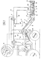
- the reference T denotes an agricultural tractor equipped with a front loader C comprising, in the usual manner, an articulated stretcher B provided at its front end with a tool-carrying frame 2.
- the loader has a pair of lifting cylinders 1 (only one of which is visible in the front view corresponding to the diagram), which make it possible to pivot the stretcher B around its axis of articulation X to cause lifting or lowering of the tool carried by the frame 2.
- the tool is not shown in Figure 1. In the following figures, it is a bucket, designated O.
- It also includes a VB tipping cylinder allowing the tool to pivot relative to the stretcher.
- the lifting cylinder 1 is double-acting. It comprises a piston 10 secured to the frame of the loader, and a cylinder 11 secured to the stretcher B.
- the tractor T is equipped with low and high pressure hydraulic sources, respectively BP (atmospheric pressure) and HP (pressure of the order of 15.10 7 to 2.10 7 Pa).
- BP atmospheric pressure
- HP pressure of the order of 15.10 7 to 2.10 7 Pa.
- Line 8 corresponds to the supply of high pressure liquid, and line 9 when returning to the tank (low pressure line).
- the conduits 8, 9 are connected, via a three-position control valve 5, on the one hand to the small chamber 101 (side of the piston rod 10) of the jack 1, on the other hand to its large chamber 100.
- This will be conventionally designated in the following description and in the claims "pressure chamber”. It is, in fact, the bringing of the liquid under pressure into this chamber 100 which causes the extension of the jack and the lifting of the tool.
- connections between the distributor 5 and the chambers 100 and 101 are referenced respectively 80-80 'and 90.
- the tool holder frame 2 which is shown even from the side on the right of the figures, comprises in the upper part, two semi-cylindrical housings 21 in which can engage appropriate pins provided on the tool.
- a pair of latches in the form of horizontal, coaxial rods 32, 33. They are carried by a jack hydraulic 3, arranged transversely, the cylinder of which is designated 31 and the piston 30.
- One 32 of the locking rods is fixed in the extension of the piston rod 30, and the other 33 on the back of the cylinder 31.
- a pair of helical springs 20 tends constantly pushing the locks 32, 33 outwards, which corresponds to the extension of the cylinder 3, in a locked position. In this position, the free end portions locks engage in appropriate receiving openings provided on the tool.
- high pressure liquid is brought into the small chamber 301 of the cylinder, while the large chamber is connected to the reservoir R (low pressure), which causes the retraction of the cylinder, and the retracting locks.
- the value of the high pressure is sufficient to overcome the force of the springs 20.
- the jack 3 is controlled by a control solenoid valve 6, with two positions.
- the chamber 301 communicates with low pressure via conduits 81, 83. In the position shown in Figures 2 and 3, it communicates with the above-mentioned line 80 '(connected to the chamber pressure cylinder 100).
- the large chamber 300 of the jack 3 is permanently connected, by a conduit 82, to the reservoir. It is therefore always subjected to low pressure.
- the solenoid valve 6 is controlled by an electric switch 700, itself actuated by a push button 70.
- the push button 70 is embedded in the handle 7.
- its support face of the finger is located at a level lower than the surface of the handle, which makes access difficult; the risk of it being pressed inadvertently is therefore practically zero.
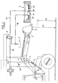
- an inclination sensor 4 of the known type. It is for example a mercury level switch, connected to the supply circuit of the solenoid valve 6. It is adjusted so that the circuit is closed when the height H 1 of the tool relative to the ground S is less than a determined height H 0 (situation illustrated in Figure 3), and open when this height H 2 is greater than H 0 ( Figure 4).
- the value of the threshold height H 0 is preferably of the order of 1.50 m, less than the average height of a person.
- the switch 700 is in the open state, which is its natural state.
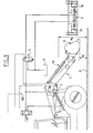
- the solenoid valve 6 is in the state of FIG. 1, so that the two chambers 300, 301 of the jack 3 are connected to the tank R and are at low pressure.
- the tool O is kept locked on the frame 2 by means of the two locks 32, 33 which are subjected to the sole action of the springs 20.
- the cylinder is therefore requested in extension, in the locking direction, this which eliminates the risk of accidental unlocking.
- the pressure in the chamber 100 of the lifting cylinder 1 is therefore low.
- the chamber 301 of the unlocking cylinder 3 is thus placed in communication, via conduits 81 and 80 ', with chamber 100.
- the latter being low insufficient pressure to overcome the springs 20, the cylinder 3 remains in extension, and the unlocking cannot take place.
- the tilt sensor 4 comes into action, keeping the supply circuit of the solenoid valve 6 open. It therefore remains in its natural state, in which the chamber 301 of the unlocking cylinder is subjected to low pressure. Unlocking is impossible. Thus, there is no risk of accident which could result from the presence of a person under the tool O at the time of its stall.
Landscapes
- Engineering & Computer Science (AREA)
- Mechanical Engineering (AREA)
- Mining & Mineral Resources (AREA)
- Civil Engineering (AREA)
- General Engineering & Computer Science (AREA)
- Structural Engineering (AREA)
- Operation Control Of Excavators (AREA)
- Forklifts And Lifting Vehicles (AREA)
- Component Parts Of Construction Machinery (AREA)
Abstract
Description
- il comporte une paire de verrous coaxiaux qui sont mobiles en translation, en sens opposés, et sont solidaires respectivement de la tige et du cylindre du vérin de déverrouillage;
- il comporte un système élastique qui sollicite les verrous dans le sens du verrouillage, à l'encontre de la pression hydraulique du vérin de déverrouillage;
- le vérin est à double-effet et la pression différentielle dans ses deux chambres tend à le maintenir en extension, dans le sens du verrouillage.
- la figure 1 est un schéma général représentatif de l'ensemble du système, appliqué à un chargeur monté sur un tracteur agricole, outil enlevé ;
- les figures 2, 3 et 4 sont des schémas similaires à la figure 1, avec l'outil en place, qui montrent des positions différentes du brancard, respectivement en position basse (de repos) (figure 2), en position légèrement relevée (figure 3), et en position haute (figure 4).
Claims (6)
- Système de verrouillage hydraulique d'un outil (O) sur le cadre porte-outil (2) d'un chargeur dont le levage du brancard (B) est commandé par un vérin hydraulique (1) - dit de levage - caractérisé par le fait qu'il comporte au moins un verrou (32, 33) commandé par un autre vérin hydraulique (3) - dit de verrouillage - qui est alimenté en liquide hydraulique, via une électrovanne (6), à partir de la chambre de pression (100) du vérin de levage (1), de telle sorte que le déverrouillage de l'outil (O) n'est possible que si la pression hydraulique régnant dans cette chambre de pression (100) excède une valeur-seuil prédéterminée.
- Système selon la revendication 1, caractérisé par le fait qu'il comporte une paire de verrous coaxiaux (32, 33) qui sont mobiles en translation, en sens opposés, et sont solidaires respectivement de la tige (30) et du cylindre (31) du vérin de déverrouillage (3).
- Système selon la revendication 2, caractérisé par le fait qu'il comporte un système élastique (20) qui sollicite les verrous (32, 33) dans le sens du verrouillage, à l'encontre de la pression hydraulique du vérin de déverrouillage (3).
- Système selon la revendication 2 ou 3, caractérisé par le fait que ledit vérin 3 est à double effet, et que la pression différentielle dans ses deux chambres (300, 301) tend à le maintenir en extension, dans le sens du verrouillage.
- Système selon l'une des revendications 1 à 4, caractérisé par le fait que ladite électrovanne (6) est commandée électriquement au moyen d'un bouton-poussoir (70) encastré dans la paroi d'une poignée de commande (7), ce qui le rend difficile d'accès.
- Système selon l'une des revendications 1 à 5, caractérisé par le fait qu'il comporte un capteur (4) d'inclinaison du brancard (B) connecté électriquement à ladite électrovanne (6) de manière à interdire la commande du vérin de déverrouillage en cas d'inclinaison excessive.
Applications Claiming Priority (2)
| Application Number | Priority Date | Filing Date | Title |
|---|---|---|---|
| FR9803563 | 1998-03-18 | ||
| FR9803563A FR2776316B1 (fr) | 1998-03-18 | 1998-03-18 | Systeme de verrouillage hydraulique d'un outil de chargeur |
Publications (2)
| Publication Number | Publication Date |
|---|---|
| EP0943738A1 true EP0943738A1 (fr) | 1999-09-22 |
| EP0943738B1 EP0943738B1 (fr) | 2003-12-17 |
Family
ID=9524391
Family Applications (1)
| Application Number | Title | Priority Date | Filing Date |
|---|---|---|---|
| EP19990460015 Expired - Lifetime EP0943738B1 (fr) | 1998-03-18 | 1999-03-03 | Système de verrouillage hydraulique d'un outil de chargeur |
Country Status (3)
| Country | Link |
|---|---|
| EP (1) | EP0943738B1 (fr) |
| DE (1) | DE69913590T2 (fr) |
| FR (1) | FR2776316B1 (fr) |
Cited By (8)
| Publication number | Priority date | Publication date | Assignee | Title |
|---|---|---|---|---|
| EP1306489A1 (fr) * | 2001-10-26 | 2003-05-02 | Agco GmbH & Co. | Chargeur frontal |
| DE10221942A1 (de) * | 2002-05-17 | 2003-12-04 | Deere & Co | Vorrichtung zum Festlegen eines Werkzeugs an einem Hubwerk |
| WO2004067855A1 (fr) * | 2003-01-30 | 2004-08-12 | Oilquick Ab | Porte-outil |
| EP1586709A3 (fr) * | 2004-04-14 | 2006-07-05 | Societe D'etudes Et D'innovation Dans Le Materiel Agricole (Seima) | Cadre porte-outil à caractère polyvalent pour chargeur, notamment à usage agricole agricole |
| FR2900170A1 (fr) * | 2006-04-21 | 2007-10-26 | Innovation Equipement Sarl | Dispositif d'accouplement hydraulique d'un godet au bout d'un bras de pelleteuse par verrouillage, deverrouillage lateral |
| EP1637659A3 (fr) * | 2001-12-06 | 2008-08-06 | Geith Patents Limited | Coupleur pour accoupler un accessoire à un bras de godet et système de commande pour un tel coupleur |
| WO2012122469A1 (fr) * | 2011-03-10 | 2012-09-13 | Clark Equipment Company | Système de couplage d'outil pour machine électrique |
| EP2886726A1 (fr) * | 2013-12-23 | 2015-06-24 | JC Bamford Excavators Ltd | Dispositif de désarmement |
Families Citing this family (2)
| Publication number | Priority date | Publication date | Assignee | Title |
|---|---|---|---|---|
| IES20040194A2 (en) | 2003-09-18 | 2005-03-23 | Caroline Mccormick | An excavator tool quick attachment device |
| DE102005033535A1 (de) * | 2005-07-14 | 2007-01-18 | Deere & Company, Moline | Hydraulische Anordnung |
Citations (6)
| Publication number | Priority date | Publication date | Assignee | Title |
|---|---|---|---|---|
| US3268101A (en) * | 1961-03-27 | 1966-08-23 | Allis Chalmers Mfg Co | Side dump bucket |
| FR2304726A1 (fr) * | 1975-03-18 | 1976-10-15 | Liebherr Hydraulikbagger | Appareil hydraulique de travaux publics |
| EP0184282A1 (fr) * | 1984-12-07 | 1986-06-11 | Paul Owen Jones | Dispositif d'attache rapide de sûreté |
| EP0447119A1 (fr) * | 1990-03-07 | 1991-09-18 | Swift Hitch Limited | Engin de terrassement |
| US5727342A (en) * | 1996-04-18 | 1998-03-17 | Wain-Roy, Inc. | Hydraulic latch pin assembly for coupling a tool to a construction equipment |
| US5727442A (en) * | 1994-03-02 | 1998-03-17 | Wimmer Hartstahl Ges.Mbh & Co. Kg | Safety device at hydraulic piston-cylinder units |
-
1998
- 1998-03-18 FR FR9803563A patent/FR2776316B1/fr not_active Expired - Fee Related
-
1999
- 1999-03-03 DE DE1999613590 patent/DE69913590T2/de not_active Expired - Fee Related
- 1999-03-03 EP EP19990460015 patent/EP0943738B1/fr not_active Expired - Lifetime
Patent Citations (6)
| Publication number | Priority date | Publication date | Assignee | Title |
|---|---|---|---|---|
| US3268101A (en) * | 1961-03-27 | 1966-08-23 | Allis Chalmers Mfg Co | Side dump bucket |
| FR2304726A1 (fr) * | 1975-03-18 | 1976-10-15 | Liebherr Hydraulikbagger | Appareil hydraulique de travaux publics |
| EP0184282A1 (fr) * | 1984-12-07 | 1986-06-11 | Paul Owen Jones | Dispositif d'attache rapide de sûreté |
| EP0447119A1 (fr) * | 1990-03-07 | 1991-09-18 | Swift Hitch Limited | Engin de terrassement |
| US5727442A (en) * | 1994-03-02 | 1998-03-17 | Wimmer Hartstahl Ges.Mbh & Co. Kg | Safety device at hydraulic piston-cylinder units |
| US5727342A (en) * | 1996-04-18 | 1998-03-17 | Wain-Roy, Inc. | Hydraulic latch pin assembly for coupling a tool to a construction equipment |
Cited By (15)
| Publication number | Priority date | Publication date | Assignee | Title |
|---|---|---|---|---|
| EP1306489A1 (fr) * | 2001-10-26 | 2003-05-02 | Agco GmbH & Co. | Chargeur frontal |
| EP1637659A3 (fr) * | 2001-12-06 | 2008-08-06 | Geith Patents Limited | Coupleur pour accoupler un accessoire à un bras de godet et système de commande pour un tel coupleur |
| DE10221942A1 (de) * | 2002-05-17 | 2003-12-04 | Deere & Co | Vorrichtung zum Festlegen eines Werkzeugs an einem Hubwerk |
| EP1362956A3 (fr) * | 2002-05-17 | 2003-12-10 | Deere & Company | Dispositif pour verrouiller un outil sur un bras élévateur |
| US7001137B2 (en) | 2002-05-17 | 2006-02-21 | Deere & Company | Arrangement for securing an implement to a lifting arm |
| US7654787B2 (en) | 2003-01-30 | 2010-02-02 | Oilquick Ab | Tool holder with hydraulic coupling means |
| WO2004067855A1 (fr) * | 2003-01-30 | 2004-08-12 | Oilquick Ab | Porte-outil |
| EP1586709A3 (fr) * | 2004-04-14 | 2006-07-05 | Societe D'etudes Et D'innovation Dans Le Materiel Agricole (Seima) | Cadre porte-outil à caractère polyvalent pour chargeur, notamment à usage agricole agricole |
| FR2900170A1 (fr) * | 2006-04-21 | 2007-10-26 | Innovation Equipement Sarl | Dispositif d'accouplement hydraulique d'un godet au bout d'un bras de pelleteuse par verrouillage, deverrouillage lateral |
| WO2012122469A1 (fr) * | 2011-03-10 | 2012-09-13 | Clark Equipment Company | Système de couplage d'outil pour machine électrique |
| CN103415665A (zh) * | 2011-03-10 | 2013-11-27 | 克拉克设备公司 | 用于动力机的设备联接系统 |
| CN103415665B (zh) * | 2011-03-10 | 2016-01-13 | 克拉克设备公司 | 用于动力机的设备联接系统 |
| US9334623B2 (en) | 2011-03-10 | 2016-05-10 | Clark Equipment Company | Implement coupling system for a power machine |
| EP2886726A1 (fr) * | 2013-12-23 | 2015-06-24 | JC Bamford Excavators Ltd | Dispositif de désarmement |
| GB2522968A (en) * | 2013-12-23 | 2015-08-12 | Bamford Excavators Ltd | A disarm device |
Also Published As
| Publication number | Publication date |
|---|---|
| EP0943738B1 (fr) | 2003-12-17 |
| FR2776316A1 (fr) | 1999-09-24 |
| DE69913590D1 (de) | 2004-01-29 |
| FR2776316B1 (fr) | 2000-06-16 |
| DE69913590T2 (de) | 2004-09-30 |
Similar Documents
| Publication | Publication Date | Title |
|---|---|---|
| EP0626292B1 (fr) | Siège de véhicule comportant un écran escamotable dans l'accoudoir | |
| EP0943738B1 (fr) | Système de verrouillage hydraulique d'un outil de chargeur | |
| FR2908498A1 (fr) | Dispositif porteur | |
| FR2850988A1 (fr) | Appareil de securite a levier de commande pour une machine de travaux publics | |
| EP3908547B1 (fr) | Nacelle elevatrice a pupitre de commande amovible comprenant une protection anti-ecrasement de l'operateur | |
| FR2908497A1 (fr) | Dispositif porteur | |
| EP0051100A1 (fr) | Arceau de sécurité pivotant pour véhicule, notamment pour tracteur porte-outils | |
| FR2688378A1 (fr) | Dispositif de relevage avant, pour tracteur agricole ou analogue, et porte-masse pour un tel dispositif. | |
| EP1386031A1 (fr) | Planche a repasser reglable en hauteur | |
| EP0728600B1 (fr) | Dispositif à crochet relevable pour le tractage de véhicules | |
| FR2512335A1 (fr) | Ensemble de siege a deux positions, notamment pour vehicule de manutention de materiaux | |
| FR2531303A2 (fr) | Dispositif destine a ameliorer l'adherence au sol de tracteurs portant des outils de travail du sol | |
| FR2480264A1 (fr) | Dispositif de securite pour appareils de levage a nacelle porte-personnes pour l'entretien aerien | |
| FR3028398A1 (fr) | Mobilier comprenant un corps supporte par des pieds | |
| WO1997035060A1 (fr) | Presse a repasser | |
| EP0474520B1 (fr) | Dispositif d'accrochage d'un outil à l'attelage trois points d'un tracteur | |
| WO2002021898A1 (fr) | Dispositif de relevage pour tracteur permettant d'atteler et de deteler une masse sans intervention manuelle | |
| JP3692010B2 (ja) | 昇降椅子のロック装置 | |
| FR3090025A1 (fr) | Poignée de porte a double système d’ouverture | |
| EP1238896A1 (fr) | Timon articulé pour chariot de magasinage | |
| FR2698252A1 (fr) | Meuble-lit. | |
| FR2596378A1 (fr) | Dispositif chargeur a compensation rapide et blocage pour tracteurs agricoles et analogues | |
| FR2784668A1 (fr) | Chariot elevateur a fourche | |
| EP1738033B1 (fr) | Systeme de commande de la synchronisation des mouvements des deux parties d'un outil porte par un chargeur | |
| FR2783539A1 (fr) | Dispositif de commande d'un engin de travaux publics |
Legal Events
| Date | Code | Title | Description |
|---|---|---|---|
| PUAI | Public reference made under article 153(3) epc to a published international application that has entered the european phase |
Free format text: ORIGINAL CODE: 0009012 |
|
| AK | Designated contracting states |
Kind code of ref document: A1 Designated state(s): AT BE CH CY DE LI |
|
| AX | Request for extension of the european patent |
Free format text: AL;LT;LV;MK;RO;SI |
|
| 17P | Request for examination filed |
Effective date: 20000119 |
|
| AKX | Designation fees paid |
Free format text: AT BE CH CY DE LI |
|
| RBV | Designated contracting states (corrected) |
Designated state(s): DE ES FR GB IT |
|
| 17Q | First examination report despatched |
Effective date: 20020923 |
|
| GRAH | Despatch of communication of intention to grant a patent |
Free format text: ORIGINAL CODE: EPIDOS IGRA |
|
| GRAS | Grant fee paid |
Free format text: ORIGINAL CODE: EPIDOSNIGR3 |
|
| GRAA | (expected) grant |
Free format text: ORIGINAL CODE: 0009210 |
|
| AK | Designated contracting states |
Kind code of ref document: B1 Designated state(s): DE ES FR GB IT |
|
| PG25 | Lapsed in a contracting state [announced via postgrant information from national office to epo] |
Ref country code: IT Free format text: LAPSE BECAUSE OF FAILURE TO SUBMIT A TRANSLATION OF THE DESCRIPTION OR TO PAY THE FEE WITHIN THE PRESCRIBED TIME-LIMIT;WARNING: LAPSES OF ITALIAN PATENTS WITH EFFECTIVE DATE BEFORE 2007 MAY HAVE OCCURRED AT ANY TIME BEFORE 2007. THE CORRECT EFFECTIVE DATE MAY BE DIFFERENT FROM THE ONE RECORDED. Effective date: 20031217 Ref country code: ES Free format text: LAPSE BECAUSE OF FAILURE TO SUBMIT A TRANSLATION OF THE DESCRIPTION OR TO PAY THE FEE WITHIN THE PRESCRIBED TIME-LIMIT Effective date: 20031217 |
|
| REG | Reference to a national code |
Ref country code: GB Ref legal event code: FG4D Free format text: NOT ENGLISH |
|
| REF | Corresponds to: |
Ref document number: 69913590 Country of ref document: DE Date of ref document: 20040129 Kind code of ref document: P |
|
| GBT | Gb: translation of ep patent filed (gb section 77(6)(a)/1977) |
Effective date: 20040303 |
|
| PLBE | No opposition filed within time limit |
Free format text: ORIGINAL CODE: 0009261 |
|
| STAA | Information on the status of an ep patent application or granted ep patent |
Free format text: STATUS: NO OPPOSITION FILED WITHIN TIME LIMIT |
|
| 26N | No opposition filed |
Effective date: 20040920 |
|
| PGFP | Annual fee paid to national office [announced via postgrant information from national office to epo] |
Ref country code: DE Payment date: 20090414 Year of fee payment: 11 |
|
| PGFP | Annual fee paid to national office [announced via postgrant information from national office to epo] |
Ref country code: FR Payment date: 20090326 Year of fee payment: 11 |
|
| PGFP | Annual fee paid to national office [announced via postgrant information from national office to epo] |
Ref country code: GB Payment date: 20090417 Year of fee payment: 11 |
|
| GBPC | Gb: european patent ceased through non-payment of renewal fee |
Effective date: 20100303 |
|
| REG | Reference to a national code |
Ref country code: FR Ref legal event code: ST Effective date: 20101130 |
|
| PG25 | Lapsed in a contracting state [announced via postgrant information from national office to epo] |
Ref country code: FR Free format text: LAPSE BECAUSE OF NON-PAYMENT OF DUE FEES Effective date: 20100331 |
|
| PG25 | Lapsed in a contracting state [announced via postgrant information from national office to epo] |
Ref country code: DE Free format text: LAPSE BECAUSE OF NON-PAYMENT OF DUE FEES Effective date: 20101001 |
|
| PG25 | Lapsed in a contracting state [announced via postgrant information from national office to epo] |
Ref country code: GB Free format text: LAPSE BECAUSE OF NON-PAYMENT OF DUE FEES Effective date: 20100303 |