EP0943745A2 - Dispositif d'ancrage d'une barre de mise en tension, dans une masse de béton armé - Google Patents
Dispositif d'ancrage d'une barre de mise en tension, dans une masse de béton armé Download PDFInfo
- Publication number
- EP0943745A2 EP0943745A2 EP99810233A EP99810233A EP0943745A2 EP 0943745 A2 EP0943745 A2 EP 0943745A2 EP 99810233 A EP99810233 A EP 99810233A EP 99810233 A EP99810233 A EP 99810233A EP 0943745 A2 EP0943745 A2 EP 0943745A2
- Authority
- EP
- European Patent Office
- Prior art keywords
- holder
- rod
- opening
- parts
- protective tube
- Prior art date
- Legal status (The legal status is an assumption and is not a legal conclusion. Google has not performed a legal analysis and makes no representation as to the accuracy of the status listed.)
- Granted
Links
- 238000004873 anchoring Methods 0.000 title claims description 29
- 239000011150 reinforced concrete Substances 0.000 title claims description 3
- 230000001681 protective effect Effects 0.000 claims description 39
- 238000009434 installation Methods 0.000 claims description 26
- 230000002787 reinforcement Effects 0.000 claims description 7
- 239000000463 material Substances 0.000 claims description 4
- 230000000149 penetrating effect Effects 0.000 claims description 4
- 238000007789 sealing Methods 0.000 claims description 4
- 230000000284 resting effect Effects 0.000 claims 1
- 238000010276 construction Methods 0.000 abstract description 3
- 239000004567 concrete Substances 0.000 description 12
- XEEYBQQBJWHFJM-UHFFFAOYSA-N Iron Chemical compound [Fe] XEEYBQQBJWHFJM-UHFFFAOYSA-N 0.000 description 6
- 238000004519 manufacturing process Methods 0.000 description 4
- 229910052742 iron Inorganic materials 0.000 description 3
- 210000002414 leg Anatomy 0.000 description 3
- 125000006850 spacer group Chemical group 0.000 description 3
- 230000015572 biosynthetic process Effects 0.000 description 2
- 229910000831 Steel Inorganic materials 0.000 description 1
- 239000011230 binding agent Substances 0.000 description 1
- 238000004140 cleaning Methods 0.000 description 1
- 239000002131 composite material Substances 0.000 description 1
- 230000007797 corrosion Effects 0.000 description 1
- 238000005260 corrosion Methods 0.000 description 1
- 238000009415 formwork Methods 0.000 description 1
- 238000003780 insertion Methods 0.000 description 1
- 230000037431 insertion Effects 0.000 description 1
- 239000007788 liquid Substances 0.000 description 1
- 239000002184 metal Substances 0.000 description 1
- 229910052751 metal Inorganic materials 0.000 description 1
- 238000012986 modification Methods 0.000 description 1
- 230000004048 modification Effects 0.000 description 1
- 230000035515 penetration Effects 0.000 description 1
- 230000000630 rising effect Effects 0.000 description 1
- 230000006641 stabilisation Effects 0.000 description 1
- 238000011105 stabilization Methods 0.000 description 1
- 239000010959 steel Substances 0.000 description 1
- 210000000689 upper leg Anatomy 0.000 description 1
Images


Classifications
-
- E—FIXED CONSTRUCTIONS
- E04—BUILDING
- E04C—STRUCTURAL ELEMENTS; BUILDING MATERIALS
- E04C5/00—Reinforcing elements, e.g. for concrete; Auxiliary elements therefor
- E04C5/08—Members specially adapted to be used in prestressed constructions
- E04C5/12—Anchoring devices
Definitions
- the invention relates to a device for anchoring a tie rod in a reinforced concrete mass, with one for laying and fastening on the Reinforcement provided holder element, the tie rod the holder element penetrates and through the holder element at a predetermined angle is held to the support plane of the holder element.
- Single-sided concrete walls are made with the help of trestles.
- the up for complete hardening of the concrete mass to be picked up from the trestles Concrete pressure is introduced into the ground via tension rods.
- the Tension rod via a holder plate tied to the upper reinforcement layer fixed for concreting.
- the holder plate has a correspondingly angled V-shaped Middle part on.
- This guide part enables a stable position and direction Installation of the tie rod.
- the disadvantage of this anchoring device is that in addition to the holder plate, a separate guide sleeve for the tie rod must be provided, mainly due to the increase of the production costs for the anchoring device.
- the invention is therefore based on the object of a device at the outset to create the type mentioned, which overcomes the aforementioned disadvantages, is inexpensive to manufacture and easy to use position and directionally stable installation of a tie rod enables.
- the holder element leads to the achievement of the object according to the invention consists of two holder parts, at least a first holder part one for Implementation of the tie rod provided opening, the opening width is selected in at least one direction so that the maximum possible Tilt angle of the tie rod corresponds to the installation angle, and where the second holder part is arranged at a distance from the opening in the first holder part Stop for fixing the tension rod in the specified installation angle having.
- At least those holder parts which have openings as plate-shaped flat parts designed, wherein the holder element preferably from a single Flat part blank is shaped.
- the second one Holder part also an opening provided for the passage of the tie rod on.
- the stop for fixing the tie rod in the predetermined installation angle formed by part of the opening are the plate-shaped flat parts in this embodiment arranged parallel to each other, so that openings of the same dimension can be arranged. Basically, however the two holder parts in a wide range at any angle to each other stand.
- the plate-shaped flat parts are essentially vertical arranged to each other.
- the second holder part is preferably made of Part of the first holder part is punched out and out of the support plane of the holder element bent into its final position.
- the two are Holder parts formed from rod or wire material
- the holder element is preferably formed from a single bar or wire blank.
- the main advantage of the holder element according to the invention over The holder plates according to the prior art is that the holder parts in a simple way for screwing a tie rod into the holder element can be prepared by just the shape of the openings in the holder parts and, if necessary, the mutual distance between the two openings in the holder parts to the thread of a screwable into the holder element Must be adjusted.
- the invention Device penetrates one provided for receiving the tie rod Protection tube the openings in the holder parts and is non-positive in these and held in the specified installation angle via the stop.
- the Protective tube is put together a sleeve-shaped anchoring element, this anchoring element on the one hand a threaded part for a this usable tie rod and on the other hand an anchoring part for Remains in the concrete mass.
- any materials can be used to manufacture the holder element are used, which meet the requirements regarding deformability, mechanical strength and corrosion resistance.
- a preferred one Material is steel, but there are also designs in, for example Plastic or composite materials possible.
- Anchoring device with a protective tube are the openings in the holder parts designed so that the standardized and on construction sites Spacer tubes usually used in the inventive Holder element can be used and the specified installation angle without further measures.
- the outside diameter is the same of the sleeve-shaped anchoring element in the area of it Plug connection with the protective tube the inside diameter of the standardized Spacer tubes adapted. This has the advantage of being a standard spacer tube in the anchoring element according to the invention without further ado Protection tube can be used.
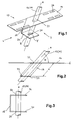
- a holder element 10 for a tie rod 12 shown in FIGS. 1 to 3 or for a protective tube 14 provided for receiving a tension rod has a strip-shaped support plate 16. Approximately in the middle of a longitudinal side edge the support plate 16 protrudes at right angles to this and with a Inclination according to the axial direction z of the tie rod 12 or a protective strip 14 from a side strip 18. The free end of the side strip 18 is bent at right angles to a holder strip 20, so that it is cross-sectional results in a C-shaped profile, the support plate 16 and the holder strips 20 are parallel to each other.
- an opening 22, 24 is arranged for the passage of the tie rod 12 and the protective tube 14, respectively.
- the dimension of the openings 22, 24 at a distance from one another is selected such that the tension rod 12 or the protective tube 14 inserted into the holder element 10 assumes the maximum possible angle of inclination and is thus held in the holder element 10 in a positive and / or non-positive manner .
- the maximum possible installation angle of the tension rod 12 or the protective tube 14 corresponds to the predetermined installation angle ⁇ with respect to a support plane E defined by the support plate 16.
- the shape and the dimension of the two openings 22, 24 can vary within wide limits.
- the opening width in the direction of inclination is decisive for setting the installation angle ⁇ ; this is corresponding to the installation angle ⁇ to be set larger than the diameter D of the tension rod 12 or the protective tube 14.
- the shape of the opening 22, 24 is, for example, an ellipse, the small diameter Y of which essentially corresponds to the diameter D of the tension rod 12 or the protective tube 14 corresponds and whose large diameter X is selected so that the desired installation angle ⁇ between the rod or protective tube axis z and the support plane E is obtained.
- strip-shaped platen 16 are to facilitate tying the holder plate 10 on a reinforcement layer longitudinal slots 26 for Carrying iron trusses arranged.
- the strip-shaped Platen 16 at one end to form the side stripe 18 and the holder strip 20 bent twice at right angles.
- the support plate is also here 16 and the holder strip 20 arranged parallel to each other.
- the location of the openings 22, 24 corresponds to that of FIG. 1.
- a holder element 10 shown in FIG. 5 is made of a sheet metal blank to form a U-shaped cross section with parallel mutually standing leg strips 28, 30 are formed.
- openings 32, 34 are arranged in pairs. These openings 32, 34 can have the same or different dimensions in pairs and also define different installation angles ⁇ . This makes it possible only holder element for tie rods 12 or protective tubes 14 different To provide diameters. It should be noted here that for a screw-in tie rod, the shape of the openings and, if applicable, mutual distance of the openings can be easily adjusted can.
- FIG. 6 shows a holder element 10 in which the strip-shaped support plate 16 is bent at the end to the holder strip 20.
- the tie rod 12 or that Protective tube 14 penetrates the opening 22 in the support plate 16 and is from Holder strip 20, the free end of which forms a stop 36, in its Installation angle a corresponding maximum inclination angle fixed.
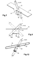
- FIG. 7 is the same in the embodiment of a holder element 10 according to FIG Way as in the embodiment according to FIGS. 1 to 3 on the platen 16 approximately in the middle of one of its longitudinal edges of the side strips 18 below Formation of a stop strip 42 bent twice at right angles.
- This Embodiment corresponds essentially to that of FIGS. 1 to 3, wherein however, only the opening 22 is present in the platen and the holder strip 20 with opening 24 on the minimally required stop strips 42, whose one longitudinal edge forms the stop 36 has been reduced.
- Fig. 8 is a modification of the holder element of Fig. 7, wherein the stop strip 42 chosen so wide and positioned is that it has two stops 36a, b for the two possible tilt positions the tension rod 12 or the protective tube 14 offers.
- this Holder element can thus be a tension rod 12 penetrating opening 22 or a protective tube 14 can be positioned in two different directions.
- holder element 8 modified variant is instead of the wide stop strip 42 a holder part with two differently dimensioned openings for example for a tie rod and a protective tube.
- the opening 22 in the holder part 16 is dimensioned in this case so that it forms a stop for both a tie rod and a protective tube.
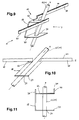
- FIGS. 9 to 11 10 are two instead of a strip-shaped support plate 16
- Support strips 38, 40 are provided.
- a first support strip 38 protrudes from the side strip in one direction in the support plane E.
- the second support strip 40 is with the side strip 18 via a stop strip 42 forming connecting web and protrudes into the first contact strip 38 opposite direction in the support plane E.
- From the hard shoulder 18 protrudes at right angles from the holder strip 20 with the opening 24.
- An in the opening 24 inserted tie rod 12 or a protective tube 14 is from Stop 42 in its inclined position predetermined by opening 24 Formation of the installation angle a held non-positively.
- the support strips 38, 40 rising from the support level E are on their Roughened upper edge or provided with teeth 44. This gives a better position stabilization of the holder element 10, if this with Iron trusses are tied to a reinforcement. Of course you can the support strips 38, 40 also with slots or holes for implementation be provided by iron binders.
- the embodiment variant of a holder element 10 shown in FIG. 12 is from a wire or rod 46 formed.
- a first support loop 48 forms the support plane E.
- An additional turn delimits an opening 50 for Implementation of a tie rod 12 or a protective tube 14.
- the wire or the rod 46 is to a further holder loop 52 as a second opening formed at a distance a from the first opening 50.
- 12 is readily understandable that instead of a closed holder loop 52, a stop for fixing the tension rod 12 or the protective tube 14 in its maximum, the inclination corresponding to the installation angle ⁇ is sufficient.
- Opening loops for the passage of a tie rod or a protective tube to arrange, such as above in connection with that of Fig. 8 modified embodiment is described.
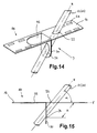
- FIGS. 1 to 12 and 14 and 15 represent only a small selection from a large number of possible variations a holder element with two openings or one opening and a stop for fixing a tie rod or a protective tube represents.
- an anchoring device shown in FIG. 13 1 is a protective tube 14 made of plastic inserted into the openings 22, 24 in the support plate 16 or in the holder strip 20.
- An anchoring element 56 with a threaded part 58 and one Anchoring part 60 is inserted into protective tube 14 at one end.
- the tie rod 12 passes through the protective tube 14 and is with the threaded part 58 of the anchoring element 56 screwed.
- the free end of the protective tube 14 is a closure cap 62 is placed. From the inner wall of the cap 62 protrudes an integrally molded flexible and tapering inward trained sealing ring 64 from, the clear width about the core diameter of the tie rod 12 used corresponds.
- an opening for the tie rod 10 to be used later closing plug 66 may be provided as a lid.
- the anchoring element 56 is positioned before the pouring the concrete mass 68 by tying the holder element 10 to the upper Reinforcement layer 54 of reinforcement.
- the holder member 10 can Slots 26 are tied in the platen 16.
- a wall formwork created and supported on trestles After pouring and hardening the concrete mass 68, a wall formwork created and supported on trestles.
- the trestles are in in a known manner via the tie rod protruding from the concrete mass 68 12 anchored. It is particularly important that the tension rod in an angle of 45 ° to the foundation is built in, because of the manufacturing the concrete pressure on the wall is anchored in the floor slab or must be introduced into the foundation. Because the dimension of Openings 22, 24 in the support plate 16 and in the holder strip 20 are selected in this way is that an inserted tie rod or a protective tube with the support level E of the support plate 16 the predetermined angle ⁇ of 45 °, for example forms, the angle of inclination of the protective tube 14 to the foundation professional arrangement of the holder element also 45 °. After making the wall becomes the tie rod 12 from the anchoring element 56 unscrewed and can be used again. That in the concrete mass 68 Protective tube 14 remaining is then cut off at ground level.
- a second holder part 70 is partially punched out of the strip-shaped support plate 16 and at right angles leaving an opening 72 in the platen 16 bent over to this.
Landscapes
- Engineering & Computer Science (AREA)
- Architecture (AREA)
- Civil Engineering (AREA)
- Structural Engineering (AREA)
- Joining Of Building Structures In Genera (AREA)
- Piles And Underground Anchors (AREA)
- Reinforcement Elements For Buildings (AREA)
Applications Claiming Priority (2)
| Application Number | Priority Date | Filing Date | Title |
|---|---|---|---|
| CH65398 | 1998-03-18 | ||
| CH65398 | 1998-03-18 |
Publications (3)
| Publication Number | Publication Date |
|---|---|
| EP0943745A2 true EP0943745A2 (fr) | 1999-09-22 |
| EP0943745A3 EP0943745A3 (fr) | 2001-01-10 |
| EP0943745B1 EP0943745B1 (fr) | 2005-05-04 |
Family
ID=4192028
Family Applications (1)
| Application Number | Title | Priority Date | Filing Date |
|---|---|---|---|
| EP99810233A Expired - Lifetime EP0943745B1 (fr) | 1998-03-18 | 1999-03-15 | Dispositif d'ancrage d'une barre de mise en tension, dans une masse de béton armé |
Country Status (3)
| Country | Link |
|---|---|
| EP (1) | EP0943745B1 (fr) |
| AT (1) | ATE294904T1 (fr) |
| DE (1) | DE59911998D1 (fr) |
Cited By (4)
| Publication number | Priority date | Publication date | Assignee | Title |
|---|---|---|---|---|
| DE10258435A1 (de) * | 2002-12-13 | 2004-08-12 | Doka Industrie Gmbh | Ankerhalter |
| WO2006134266A1 (fr) | 2005-06-15 | 2006-12-21 | Tolemecane Sas | Support de coffrage et de traversee pour conduits, cables et gaines flexibles |
| WO2010051379A1 (fr) * | 2008-10-31 | 2010-05-06 | Simpson Strong-Tie Company, Inc. | Oreille de cisaillement pour ossature |
| EP2096223A3 (fr) * | 2008-02-27 | 2012-06-06 | Pino Albanese | Dispositif de positionnement et d'ancrage à position et angle précis d'une barre de tension |
Citations (2)
| Publication number | Priority date | Publication date | Assignee | Title |
|---|---|---|---|---|
| DE9314656U1 (de) | 1992-09-30 | 1994-01-27 | Albanese, Giulio, Winterthur | Distanzrohr |
| DE4234892A1 (de) | 1992-10-16 | 1994-05-19 | Karl Bisani | Vorrichtung zum lage- und richtungsstabilen Einbau von Verankerungsteilen in Beton |
Family Cites Families (5)
| Publication number | Priority date | Publication date | Assignee | Title |
|---|---|---|---|---|
| US5388804A (en) * | 1993-07-19 | 1995-02-14 | Cohen; Jack H. | Anchor bolt holder-spacer |
| US5670076A (en) * | 1994-08-04 | 1997-09-23 | Simpson Strong-Tie Company, Inc. | Reusable coupler for foundation anchor |
| CH690727A5 (de) * | 1995-11-09 | 2000-12-29 | Giulio Albanese | Hülsenförmiges Verankerungselement zum Einbetten in eine Betongiessmasse. |
| US5937609A (en) * | 1995-11-27 | 1999-08-17 | Roth; Steven A. | Concrete insert to support anchor bolt |
| DK0943744T3 (da) * | 1998-03-20 | 2004-06-07 | Reto Bonomo | Fremgangsmåde og element til indföring af forskydningskræfter i et betonlegeme og et armeret betonlegeme |
-
1999
- 1999-03-15 DE DE59911998T patent/DE59911998D1/de not_active Expired - Lifetime
- 1999-03-15 EP EP99810233A patent/EP0943745B1/fr not_active Expired - Lifetime
- 1999-03-15 AT AT99810233T patent/ATE294904T1/de active
Patent Citations (2)
| Publication number | Priority date | Publication date | Assignee | Title |
|---|---|---|---|---|
| DE9314656U1 (de) | 1992-09-30 | 1994-01-27 | Albanese, Giulio, Winterthur | Distanzrohr |
| DE4234892A1 (de) | 1992-10-16 | 1994-05-19 | Karl Bisani | Vorrichtung zum lage- und richtungsstabilen Einbau von Verankerungsteilen in Beton |
Cited By (10)
| Publication number | Priority date | Publication date | Assignee | Title |
|---|---|---|---|---|
| DE10258435A1 (de) * | 2002-12-13 | 2004-08-12 | Doka Industrie Gmbh | Ankerhalter |
| AT500503A1 (de) * | 2002-12-13 | 2006-01-15 | Doka Ind Gmbh | Ankerhalter |
| AT500503B1 (de) * | 2002-12-13 | 2006-07-15 | Doka Ind Gmbh | Verankerungselement |
| DE10258435B4 (de) * | 2002-12-13 | 2008-03-13 | Doka Industrie Gmbh | Verankerungselement |
| WO2006134266A1 (fr) | 2005-06-15 | 2006-12-21 | Tolemecane Sas | Support de coffrage et de traversee pour conduits, cables et gaines flexibles |
| FR2887320A1 (fr) * | 2005-06-15 | 2006-12-22 | Tolemecane Sarl | Support de coffrage et de traversee pour conduits, cables et gaines flexibles. |
| EP2096223A3 (fr) * | 2008-02-27 | 2012-06-06 | Pino Albanese | Dispositif de positionnement et d'ancrage à position et angle précis d'une barre de tension |
| EP2977520A1 (fr) * | 2008-02-27 | 2016-01-27 | Pino Albanese | Procede de positionnement selon un angle precis et une position precise et ancrage d'une barre de tension |
| WO2010051379A1 (fr) * | 2008-10-31 | 2010-05-06 | Simpson Strong-Tie Company, Inc. | Oreille de cisaillement pour ossature |
| US8336267B2 (en) | 2008-10-31 | 2012-12-25 | Simpson Strong-Tie Company, Inc. | Construction frame shear lug |
Also Published As
| Publication number | Publication date |
|---|---|
| EP0943745B1 (fr) | 2005-05-04 |
| DE59911998D1 (de) | 2005-06-09 |
| ATE294904T1 (de) | 2005-05-15 |
| EP0943745A3 (fr) | 2001-01-10 |
Similar Documents
| Publication | Publication Date | Title |
|---|---|---|
| DE69837524T2 (de) | Verfahren zur Herstellung einer Verankerung, Verankerungsteil und Spannelement zu diesem Zweck | |
| DE3224986C2 (de) | Vorrichtung zur Befestigung von Montageteilen an einer Betonwand | |
| EP4053351B1 (fr) | Coffrage pour joints de dilatation pourvu de dispositif de serrage | |
| DE2229093A1 (de) | Montage bzw Befestigungsglied fur eine Bewehrung oder ein Bewehrungselement im Stahlbetonbau | |
| EP0943745B1 (fr) | Dispositif d'ancrage d'une barre de mise en tension, dans une masse de béton armé | |
| DE102019122106B3 (de) | Zaunerweiterungsvorrichtung | |
| EP0077877B1 (fr) | Ancrage pour échelons dans des pièces en béton ou similaires | |
| EP0697047B1 (fr) | Dispositif pour l'ancrage de montants de barrieres de securite dans un sol | |
| DE19548440A1 (de) | Wandelement | |
| EP2516761B1 (fr) | Dispositif permettant de raccorder deux éléments de construction séparés par un joint et d'absorber des efforts de cisaillement apparaissant entre les éléments de construction | |
| EP3892789B1 (fr) | Système de coffrage | |
| DE19645759C2 (de) | Hülsenförmiges Verankerungselement zum Einbetten in eine Betongießmasse | |
| DE2732183B2 (de) | Verbindung zweier mit ihren Stirnflächen einander gegenüberliegenden Stahlbetonteile | |
| EP0161634A2 (fr) | Poussard en particulier applicable aux travaux de blindage, p.e. blindage de tranchée | |
| DE10258435B4 (de) | Verankerungselement | |
| DE19537373A1 (de) | Verfahren und Vorrichtung zur biegesteifen Sicherung eines Schornsteins | |
| DE19517233C2 (de) | Vermarkungseinrichtung zur Befestigung von Vermessungspunkten | |
| DE1609878A1 (de) | Aus Stahl gefertigte Hohlsaeule mit Fussplatte zur Verwendung in Stahlskelettbauten | |
| DE19810034C2 (de) | Anschlagshalter für eine Wandschalung | |
| EP2096223B1 (fr) | Dispositif de positionnement et d'ancrage à position et angle précis d'une barre de tension | |
| DE29617673U1 (de) | Abschalelement | |
| AT405958B (de) | Verfahren zur herstellung eines streifenförmigen gitterelements | |
| DE1900476C3 (de) | Haltevorrichtung für Pfosten eines Schutzgeländers | |
| DE202023103836U1 (de) | Positioniervorrichtung | |
| DE29517654U1 (de) | Einrichtung zur Festlegung eines Meßpunktes in einem Gelände |
Legal Events
| Date | Code | Title | Description |
|---|---|---|---|
| PUAI | Public reference made under article 153(3) epc to a published international application that has entered the european phase |
Free format text: ORIGINAL CODE: 0009012 |
|
| AK | Designated contracting states |
Kind code of ref document: A2 Designated state(s): AT CH DE GB LI |
|
| AX | Request for extension of the european patent |
Free format text: AL;LT;LV;MK;RO;SI |
|
| PUAL | Search report despatched |
Free format text: ORIGINAL CODE: 0009013 |
|
| AK | Designated contracting states |
Kind code of ref document: A3 Designated state(s): AT BE CH CY DE DK ES FI FR GB GR IE IT LI LU MC NL PT SE |
|
| AX | Request for extension of the european patent |
Free format text: AL;LT;LV;MK;RO;SI |
|
| RIC1 | Information provided on ipc code assigned before grant |
Free format text: 7E 04C 5/12 A, 7E 04G 21/12 B, 7E 04B 1/41 B |
|
| 17P | Request for examination filed |
Effective date: 20010703 |
|
| AKX | Designation fees paid |
Free format text: AT CH DE GB LI |
|
| 17Q | First examination report despatched |
Effective date: 20030523 |
|
| GRAP | Despatch of communication of intention to grant a patent |
Free format text: ORIGINAL CODE: EPIDOSNIGR1 |
|
| GRAS | Grant fee paid |
Free format text: ORIGINAL CODE: EPIDOSNIGR3 |
|
| GRAA | (expected) grant |
Free format text: ORIGINAL CODE: 0009210 |
|
| AK | Designated contracting states |
Kind code of ref document: B1 Designated state(s): AT CH DE GB LI |
|
| REG | Reference to a national code |
Ref country code: GB Ref legal event code: FG4D Free format text: NOT ENGLISH |
|
| REG | Reference to a national code |
Ref country code: CH Ref legal event code: EP |
|
| REF | Corresponds to: |
Ref document number: 59911998 Country of ref document: DE Date of ref document: 20050609 Kind code of ref document: P |
|
| REG | Reference to a national code |
Ref country code: CH Ref legal event code: NV Representative=s name: PATENTANWAELTE BREITER + WIEDMER AG |
|
| GBT | Gb: translation of ep patent filed (gb section 77(6)(a)/1977) |
Effective date: 20050624 |
|
| PLBE | No opposition filed within time limit |
Free format text: ORIGINAL CODE: 0009261 |
|
| STAA | Information on the status of an ep patent application or granted ep patent |
Free format text: STATUS: NO OPPOSITION FILED WITHIN TIME LIMIT |
|
| 26N | No opposition filed |
Effective date: 20060207 |
|
| REG | Reference to a national code |
Ref country code: CH Ref legal event code: NV Representative=s name: HANS RUDOLF GACHNANG PATENTANWALT |
|
| REG | Reference to a national code |
Ref country code: CH Ref legal event code: NV Representative=s name: GACHNANG AG PATENTANWAELTE, CH |
|
| PGFP | Annual fee paid to national office [announced via postgrant information from national office to epo] |
Ref country code: GB Payment date: 20180326 Year of fee payment: 20 Ref country code: DE Payment date: 20180322 Year of fee payment: 20 Ref country code: CH Payment date: 20180323 Year of fee payment: 20 |
|
| PGFP | Annual fee paid to national office [announced via postgrant information from national office to epo] |
Ref country code: AT Payment date: 20180320 Year of fee payment: 20 |
|
| REG | Reference to a national code |
Ref country code: DE Ref legal event code: R071 Ref document number: 59911998 Country of ref document: DE |
|
| REG | Reference to a national code |
Ref country code: CH Ref legal event code: PL |
|
| REG | Reference to a national code |
Ref country code: GB Ref legal event code: PE20 Expiry date: 20190314 |
|
| PG25 | Lapsed in a contracting state [announced via postgrant information from national office to epo] |
Ref country code: GB Free format text: LAPSE BECAUSE OF EXPIRATION OF PROTECTION Effective date: 20190314 |
|
| REG | Reference to a national code |
Ref country code: AT Ref legal event code: MK07 Ref document number: 294904 Country of ref document: AT Kind code of ref document: T Effective date: 20190315 |