EP0943767A2 - Ferrure pour porte ou fenêtre - Google Patents
Ferrure pour porte ou fenêtre Download PDFInfo
- Publication number
- EP0943767A2 EP0943767A2 EP99104845A EP99104845A EP0943767A2 EP 0943767 A2 EP0943767 A2 EP 0943767A2 EP 99104845 A EP99104845 A EP 99104845A EP 99104845 A EP99104845 A EP 99104845A EP 0943767 A2 EP0943767 A2 EP 0943767A2
- Authority
- EP
- European Patent Office
- Prior art keywords
- push rod
- tear
- cover rail
- longitudinal
- assembly according
- Prior art date
- Legal status (The legal status is an assumption and is not a legal conclusion. Google has not performed a legal analysis and makes no representation as to the accuracy of the status listed.)
- Granted
Links
Images




Classifications
-
- E—FIXED CONSTRUCTIONS
- E05—LOCKS; KEYS; WINDOW OR DOOR FITTINGS; SAFES
- E05C—BOLTS OR FASTENING DEVICES FOR WINGS, SPECIALLY FOR DOORS OR WINDOWS
- E05C9/00—Arrangements of simultaneously actuated bolts or other securing devices at well-separated positions on the same wing
- E05C9/18—Details of fastening means or of fixed retaining means for the ends of bars
- E05C9/1825—Fastening means
- E05C9/1833—Fastening means performing sliding movements
- E05C9/185—Fastening means performing sliding movements parallel with actuating bar
-
- E—FIXED CONSTRUCTIONS
- E05—LOCKS; KEYS; WINDOW OR DOOR FITTINGS; SAFES
- E05C—BOLTS OR FASTENING DEVICES FOR WINGS, SPECIALLY FOR DOORS OR WINDOWS
- E05C9/00—Arrangements of simultaneously actuated bolts or other securing devices at well-separated positions on the same wing
- E05C9/22—Guides for sliding bars, rods or cables
-
- E—FIXED CONSTRUCTIONS
- E05—LOCKS; KEYS; WINDOW OR DOOR FITTINGS; SAFES
- E05B—LOCKS; ACCESSORIES THEREFOR; HANDCUFFS
- E05B17/00—Accessories in connection with locks
- E05B17/007—Devices for reducing friction between lock parts
Definitions
- the invention relates to a fitting in the preamble of Specified claim 1 type.
- the fitting comprises a structural unit two rod-like elements, namely one fixed on the wing or Frame to be attached cover rail and from a below the cover rail mounted push rod.
- the push rod is activated by pressing one Handle moved lengthways.
- the push rod has working links, e.g. one Control pin, which is fixed in the longitudinal movement of the push rod with Interacts with the frame or sash, e.g. one Striker.
- the cover rail is not only used to attach the assembly but also to guide the push rod.
- A contributes to this leadership effect the cover rail arranged guide shoe, which with a The center piece engages in an elongated hole in the push rod.
- both Push rod as well as the cover rail are cut to length to match the one to be arranged next to it another unit.
- a certain position between the push rod and the cover rail be respected. This position depends on which working stroke the Has handle on the push rod and at which point the Working links of the push rod in the different working positions must be located.
- a push rod where a push bolt acts as the link arranged, there may be a need to handle the same Type the extension movement of the slide bolt on the wing opposite one To train the bolt holder differently in the frame.
- the invention has for its object an inexpensive fitting in The preamble of claim 1 to develop the type mentioned Push rod when cutting to length in a reliable, simple manner, accordingly the respective needs, brought into different starting positions can be.
- This is according to the invention by the in the characteristic of Claim 1 measures achieved, the following special Importance.
- the guide shoe is used for cohesion between the cover rail and the push rod in the unit and also guiding the push rod in its slot creates a new one Function, namely to be a carrier for shearable end stops.
- This End stops are between the core of the guide shoe on the one hand and the slot of the push rod arranged on the other hand and consist of a detachable nose and one transverse to the longitudinal movement of the push rod trending shoulder.
- These two elements are brief below “Tear tab” and "cross shoulder” are referred to. As long as the tear tab is not eliminated, it creates with the cross shoulder assigned to it first pair of end stops, which have a first defined starting position the push rod in relation to the cover rail. By this determination can then both elements of the unit together to the desired Can be cut without being in the correct position between the The push rod and cover rail in the structural unit must be observed.
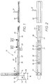
- a wing 11 preassembled unit 10 shown which consist of two interconnected Rod elements 20, 30, namely a push rod 20 and one Cover rail 30.
- the structural unit 10 shown should be in the corner region of the wing 11 be arranged and of course with connectable, not shown other units work together. According to the available Dimensions in the wing must therefore be arranged in the corner area Assembly 10, as illustrated by arrows 12 in FIGS. 1 and 2 cut a certain length. That is supposed to be through a common Cut through both rod elements 20, 30 happen.
- the push rod 20 has two working members 21, 22 in the present case, namely a slide bolt 21 provided at the rod end and one axially fixed on the push rod 20 control pin 22.
- the push rod 20 is longitudinally movable in use in the direction of arrow 23.
- the Push rod 20 is structurally connected to the cover rail 30, wherein the cover rail 30, as can be seen from the installation in FIGS. 7 and 8, by fasteners 33, such as screws, for attaching the assembly 10 on wing 11 is used. So that the longitudinal movement 23 of the push rod 20th is executable, the cover rail 30 has an outlet opening 31 for the Slide bolt 21 and an elongated hole 32 for the longitudinal movement 23 of the Control pin 22.
- the control pin 22 is namely via one of FIGS. 1 and 2 visible rivet bolt 24 firmly connected to the push rod 20.
- the Elongated hole 32 of the cover rail 30 is penetrated by the rivet bolt 24 while the control pin 22 sitting thereon on the face side of the cover rail 30 comes to lie.
- the cover rail 30 also serves to guide the longitudinally movable push rod 20.
- two guide means are provided, one of which comes from the already mentioned rivet bolt 24 and the slot 32 there.
- the other Guide means is formed by a special guide shoe 40, 3 via a rivet bolt 44 that can be seen in FIGS. 3, 4 and 5 Cover rail 30 sits.
- the guide shoe 40 has a core piece 41, the one. essentially rectangular outline profile with two each other has opposite longitudinal surfaces 42, 42 '.
- On the molded The guide shoe 40 has rivets 44 on the opposite rear side a flange plate 43 which, as best seen in Fig. 5, the Push rod 20 engages.
- To carry out the core 41 has the Push rod 20 in turn an elongated hole 25 shown in FIG. 2 in a is designed to be described in more detail.
- the cover rail 30 initially has one for the fastening means 33 Breakthrough 36, a conical depression for the view May have screw head. So that the longitudinal movement 23 of the push rod 20 not prevented by the screw 33 passing through the opening 36 is the push rod 20 in this area with a sufficient dimensioned slot 26 provided. This is particularly evident from FIG. 8 detect. But there is another breakthrough 34 in the structural unit of As can best be seen from FIG. 3, not only the cover rail 30 but especially also penetrates the guide shoe 40. The cover rail 30 and the Guide shoe 40 are then together, as also shown in FIG. 8 can be seen, penetrated by the associated screw 33.
- a handle is provided on the wing, through which Actuation of the longitudinal movement 23 of the push rod, which has already been mentioned several times 20 takes place.
- the handle actuation causes the push rod 20 moved longitudinally by the stroke distance 16.
- Fig. 1 in solid lines, one Starting position of the push rod 20 is shown, the position of which Bolt tip 27 of the aforementioned slide bolt 21 should be determined what is illustrated by the auxiliary line 14 in FIG. 1.
- Dash-dotted is in Fig. 1 also the position of the slide bolt in the after the handle operation resulting end position shown, which in Fig. 1 by the Auxiliary line 15 is clarified.
- 1 is the starting position 14 of the push rod 20 is determined by the fact that the locking tip 27 by one Line 28 opposite the angled cover rail end 38 is reset.
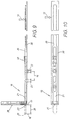
- the common cutting of the same structural unit 10 is at a given fitting of a uniform type and for a window same dimension in the cut in the area of the push rod 20 depends on whether it is in the desired first starting position 14 1 or in the second starting position 17 according to FIG. 9. With the identical sash dimension of the window, however, the cover rail 30 cut in the same place in both cases. Do you want that Separating cut 12 in FIG. 1 and 13 in FIG. 9 in both rod elements 20, Execute 30 together, the push rod 20 must in each associated initial positions 14 in Fig. 1 and 17 in Fig. 9 brought become. This requires not only a high level of attention from the mechanic but also also a lot of work for setting the respective location.
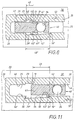
- the special feature of the invention is that the guide shoe 40 with two tear-off tabs 45, 45 'is provided. Because the guide shoe 40 is firm sits on the cover rail 30, the tear-off tabs 45, 45 'define defined Place the cover rail 30. You can now use it to define end stops generate with the push rod 20 when you are in the push rod with it interacting shoulders 19, 19 'running transversely to the longitudinal movement 23 provides, which will be referred to as "transverse shoulders" below.
- the Tear tabs 45, 45 ' are aligned transversely to one another and are located opposite each other, on the longitudinal surfaces already mentioned at the beginning 42, 42 'from the core piece 41.
- the transverse shoulders 19, 19' are by a best distance 49 shown in FIG. 11 apart.
- the assembly of the assembly 10 comes from the rod elements 20, 30 in that the guide shoe 40 with its two tear-off tabs 45, 45 'in the region of the elongated hole widenings 29 shown in FIG. 4 or 29 'is inserted and then with its bolt 44 on the cover rail 30th is riveted. Because, as shown in FIG. 6, the length 48 of the stepped extension 29 shorter than the length 48 'of opposite extension 29 'is formed, first determines the Dimensions 48 of the extension 29 with respect to the position of the push rod 20 the cover rail 30. The play of the tear-off nose 45 shown in FIG. 6 between the two level transitions 35, 19 in the extension 29 of the Length 48 is necessary to connect adjacent units serving tooth coupling between the push rod 20 with the analog to consider adjacent rod element.
- the push rod 20 has namely, as can be seen from FIGS. 1 and 2, suitable for this coupling Teeth 50.
- This second starting position is also determined by analog stops, as illustrated in FIG. 11. Now the cross shoulder 19 'of opposite step-shaped expansion 29 'effective. This happens, if the push rod 20 by the aforementioned distance 49 between the two transverse shoulders 19, 19 'is moved on. This distance 49 is however equal to the route 28 already explained in connection with FIG. 1, which, in comparison with FIG. 9, just the position difference of the latch tip 27 in the two starting positions 14 and 17 of the push rod 20 in FIG. 1 and Fig. 9 corresponds. So if the second tear-off tab 45 'in its from Fig. 11 apparent stop position is brought, where its axial end 51 'at the Cross shoulder 19 'is supported, so there is an exact adjustment of the second starting position according to FIGS. 9 and 10. This second 11 is automatically given without the Fitter needed to take care of this in detail. The fitter can now 9 and 10 to make the desired cut 13 Unit to the length corresponding to the wing 11 of FIG. 12 to cut.
- the push rod 20 can be moved through the mentioned travel 16 again Move actuation of the handle.
- the tear-off nose 45 In the first phase of this movement by exerting a limit force illustrated by arrow 53 'in FIG. 11 the tear-off nose 45 'separated over the shoulder 19'.
- the tear-off nose 45 At the final Longitudinal movement 23 of the push rod 20 according to FIG. 13 are both Tear tabs 45, 45 'sheared off.
- the guide shoe 40 is produced as an injection molded part and consists e.g. out Die-cast zinc.
- the core piece 41 For shaping the lugs 45, 45 'on the core piece 41 43 openings 57, 57 'are formed in the flange plate covering them. intended. These openings 57, 57 'are used to carry out components the injection mold.
Landscapes
- Engineering & Computer Science (AREA)
- Mechanical Engineering (AREA)
- Footwear And Its Accessory, Manufacturing Method And Apparatuses (AREA)
- Wing Frames And Configurations (AREA)
- Specific Sealing Or Ventilating Devices For Doors And Windows (AREA)
- Seal Device For Vehicle (AREA)
- Operating, Guiding And Securing Of Roll- Type Closing Members (AREA)
- Train Traffic Observation, Control, And Security (AREA)
- Window Of Vehicle (AREA)
Applications Claiming Priority (2)
| Application Number | Priority Date | Filing Date | Title |
|---|---|---|---|
| DE19811644A DE19811644C2 (de) | 1998-03-18 | 1998-03-18 | Tür- oder Fensterbeschlag |
| DE19811644 | 1998-03-18 |
Publications (3)
| Publication Number | Publication Date |
|---|---|
| EP0943767A2 true EP0943767A2 (fr) | 1999-09-22 |
| EP0943767A3 EP0943767A3 (fr) | 2003-06-04 |
| EP0943767B1 EP0943767B1 (fr) | 2004-09-22 |
Family
ID=7861241
Family Applications (1)
| Application Number | Title | Priority Date | Filing Date |
|---|---|---|---|
| EP99104845A Expired - Lifetime EP0943767B1 (fr) | 1998-03-18 | 1999-03-11 | Ferrure pour porte ou fenêtre |
Country Status (3)
| Country | Link |
|---|---|
| EP (1) | EP0943767B1 (fr) |
| AT (1) | ATE277258T1 (fr) |
| DE (2) | DE19811644C2 (fr) |
Cited By (10)
| Publication number | Priority date | Publication date | Assignee | Title |
|---|---|---|---|---|
| EP1099819A3 (fr) * | 1999-11-12 | 2002-12-18 | Roto Frank Ag | Ensemble de ferrure pour montage sur une fenêtre, une porte, ou similaire et procédé de fabrication d'un tel ensemble |
| EP1331333A3 (fr) * | 2001-12-13 | 2003-08-06 | Roto Frank Eisenwarenfabrik Aktiengesellschaft | Tige coulissante pour dispositif de fermeture pour fenêtres et/ou portes |
| WO2004007881A1 (fr) * | 2002-07-17 | 2004-01-22 | Siegenia-Aubi Kg | Dispositif de verrouillage pour une fenetre a guillotine |
| WO2009129920A1 (fr) | 2008-04-26 | 2009-10-29 | Roto Frank Ag | Ferrure pour une fenêtre, une porte ou similaire, ainsi que fenêtre, porte ou similaire avec une ferrure et procédé de verrouillage et de basculement du coin d'un battant |
| US20100218568A1 (en) * | 2008-10-03 | 2010-09-02 | Yoshikazu Nakanishi | Sliding door multipoint mortise lock with shoot bolts |
| EP2343425A1 (fr) * | 2009-12-15 | 2011-07-13 | Roto Frank Ag | Agencement de rails de partie de ferrure pour une fenêtre, une porte, un clapet ou analogue |
| CN102359316A (zh) * | 2011-10-26 | 2012-02-22 | 四川博华工程材料有限公司 | 隐形防护系统逃生解锁机构 |
| GB2513121A (en) * | 2013-04-15 | 2014-10-22 | Grouphomesafe Ltd | Shoot bolt assembly |
| EP2757217A3 (fr) * | 2013-01-17 | 2017-07-19 | MACO Technologie GmbH | Ferrure pour fenêtres ou portes |
| US11866968B2 (en) * | 2019-09-17 | 2024-01-09 | Truth Hardware Corporation | Tie bar and guide for casement window |
Families Citing this family (2)
| Publication number | Priority date | Publication date | Assignee | Title |
|---|---|---|---|---|
| DE10334933A1 (de) * | 2003-07-31 | 2005-02-24 | Aug. Winkhaus Gmbh & Co. Kg | Kippriegelverschluss für Fenster |
| CN105317290B (zh) | 2014-06-20 | 2019-04-19 | 真理五金制品公司 | 锁组件、滑动门组件以及锁致动器组件 |
Family Cites Families (6)
| Publication number | Priority date | Publication date | Assignee | Title |
|---|---|---|---|---|
| DE3240452C3 (de) * | 1982-11-02 | 1996-03-21 | Winkhaus Fa August | Treibstangenbeschlag für Fenster, Türen o. dgl. |
| DE8323365U1 (de) * | 1983-08-13 | 1983-11-24 | Siegenia-Frank Kg, 5900 Siegen | Treibstangenbeschlag fuer fenster, tueren od. dgl. |
| DE4005953A1 (de) * | 1990-02-26 | 1991-09-05 | Bilstein August Gmbh Co Kg | Beschlag fuer fenster und tueren |
| DE9100436U1 (de) * | 1991-01-15 | 1991-04-04 | Roto Frank AG, 7022 Leinfelden-Echterdingen | Befestigung eines Getriebes an einem Flügel eines Fensters, einer Tür o.dgl. |
| DE4228132A1 (de) * | 1992-08-25 | 1994-03-03 | Weidtmann Wilhelm Kg | Schließvorrichtung für Fenster, Türen o. dgl. |
| DE29601683U1 (de) * | 1996-02-02 | 1996-04-11 | Siegenia-Frank Kg, 57074 Siegen | Treibstangenbeschlag für ein Fenster, eine Tür o.dgl. |
-
1998
- 1998-03-18 DE DE19811644A patent/DE19811644C2/de not_active Expired - Fee Related
-
1999
- 1999-03-11 EP EP99104845A patent/EP0943767B1/fr not_active Expired - Lifetime
- 1999-03-11 DE DE59910552T patent/DE59910552D1/de not_active Expired - Lifetime
- 1999-03-11 AT AT99104845T patent/ATE277258T1/de active
Cited By (13)
| Publication number | Priority date | Publication date | Assignee | Title |
|---|---|---|---|---|
| EP1099819A3 (fr) * | 1999-11-12 | 2002-12-18 | Roto Frank Ag | Ensemble de ferrure pour montage sur une fenêtre, une porte, ou similaire et procédé de fabrication d'un tel ensemble |
| EP1331333A3 (fr) * | 2001-12-13 | 2003-08-06 | Roto Frank Eisenwarenfabrik Aktiengesellschaft | Tige coulissante pour dispositif de fermeture pour fenêtres et/ou portes |
| WO2004007881A1 (fr) * | 2002-07-17 | 2004-01-22 | Siegenia-Aubi Kg | Dispositif de verrouillage pour une fenetre a guillotine |
| CN102016212B (zh) * | 2008-04-26 | 2015-06-17 | 诺托·弗朗克股份有限公司 | 用于窗、门或者类似物体的配件以及带有该配件的窗、门或者类似物体,以及用于闩上和摇动支承窗扇的窗扇角的方法 |
| WO2009129920A1 (fr) | 2008-04-26 | 2009-10-29 | Roto Frank Ag | Ferrure pour une fenêtre, une porte ou similaire, ainsi que fenêtre, porte ou similaire avec une ferrure et procédé de verrouillage et de basculement du coin d'un battant |
| EA022441B1 (ru) * | 2008-04-26 | 2016-01-29 | Рото Франк Аг | Фурнитурный узел для окна или двери, окно и способ блокировки и разблокировки створки составной рамы окна |
| US20100218568A1 (en) * | 2008-10-03 | 2010-09-02 | Yoshikazu Nakanishi | Sliding door multipoint mortise lock with shoot bolts |
| US8899635B2 (en) * | 2008-10-03 | 2014-12-02 | Truth Hardware Corporation | Sliding door multipoint mortise lock with shoot bolts |
| EP2343425A1 (fr) * | 2009-12-15 | 2011-07-13 | Roto Frank Ag | Agencement de rails de partie de ferrure pour une fenêtre, une porte, un clapet ou analogue |
| CN102359316A (zh) * | 2011-10-26 | 2012-02-22 | 四川博华工程材料有限公司 | 隐形防护系统逃生解锁机构 |
| EP2757217A3 (fr) * | 2013-01-17 | 2017-07-19 | MACO Technologie GmbH | Ferrure pour fenêtres ou portes |
| GB2513121A (en) * | 2013-04-15 | 2014-10-22 | Grouphomesafe Ltd | Shoot bolt assembly |
| US11866968B2 (en) * | 2019-09-17 | 2024-01-09 | Truth Hardware Corporation | Tie bar and guide for casement window |
Also Published As
| Publication number | Publication date |
|---|---|
| EP0943767B1 (fr) | 2004-09-22 |
| DE19811644A1 (de) | 1999-09-30 |
| DE59910552D1 (de) | 2004-10-28 |
| ATE277258T1 (de) | 2004-10-15 |
| EP0943767A3 (fr) | 2003-06-04 |
| DE19811644C2 (de) | 2002-11-28 |
Similar Documents
| Publication | Publication Date | Title |
|---|---|---|
| DE2313690C2 (de) | Treibstangenbeschlag für Fenster, Türen od.dgl | |
| EP1316466A1 (fr) | Dispositif d'arrêt avec plusieurs goupilles de blocage | |
| EP1316465A1 (fr) | Dispositif d'arrêt avec goupilles de blocage rainurées | |
| EP0943767B1 (fr) | Ferrure pour porte ou fenêtre | |
| CH692878A5 (de) | Relais mit zwangsgeführten Kontaktsätzen. | |
| EP0294630B1 (fr) | Fermeture pour fenêtres, portes, etc. | |
| DE19506106C2 (de) | Beschlag für Fenster, Türen od. dgl. | |
| DE4213862C2 (de) | Blindnietartiger Klemmverbinder | |
| DE19740603C2 (de) | Stulpschienenbefestigung | |
| EP0556442B1 (fr) | Ferrure de tringle de commande pour portes, fenêtres et similaires | |
| AT396165B (de) | Kantengetriebe fuer ein fenster, eine tuer od. dgl. | |
| DE3225049C2 (de) | Treibstangenverschluß | |
| DE102009054644B4 (de) | Beschlagteilanordnung für ein Fenster, eine Tür, eine Klappe oder dergleichen | |
| DE4217748A1 (de) | Kupplungsvorrichtung für aneinanderstoßende Stulpschienen- und Treibstangenabschnitte und Verfahren zur Fertigstellung einer derartigen Kupplungsvorrichtung | |
| EP0807731A2 (fr) | Profil de verrouillage traversant | |
| EP1223273B1 (fr) | Barre d'accouplement | |
| DE19925859B4 (de) | Montagehilfe für eine Kraftfahrzeugtürkonstruktion | |
| EP1580370B1 (fr) | Ensemble ferrure | |
| DE2461228A1 (de) | Verschlussvorrichtung fuer fenster, tueren oder dergleichen | |
| EP0728889A1 (fr) | Procédé de fixation de composantes sur des profilés creux et éléments de fixation et de positionnement à utiliser dans ce procédé | |
| EP1493889A1 (fr) | Couvercle pour fermetures | |
| EP1270856B1 (fr) | Ferrure de verrouillage pour fenêtres ou portes | |
| DE69800142T2 (de) | Beschlag für Tür, Fenster o. dgl | |
| DE1908478B2 (de) | Treibstangenverbindung | |
| DE69800458T2 (de) | Stangenaustrittsführung für Treibstangen oder Treibstangenschloss |
Legal Events
| Date | Code | Title | Description |
|---|---|---|---|
| PUAI | Public reference made under article 153(3) epc to a published international application that has entered the european phase |
Free format text: ORIGINAL CODE: 0009012 |
|
| AK | Designated contracting states |
Kind code of ref document: A2 Designated state(s): AT BE CH CY DE DK ES FI FR GB GR IE IT LI LU MC NL PT SE |
|
| AX | Request for extension of the european patent |
Free format text: AL;LT;LV;MK;RO;SI |
|
| PUAL | Search report despatched |
Free format text: ORIGINAL CODE: 0009013 |
|
| RIC1 | Information provided on ipc code assigned before grant |
Ipc: 7E 05B 17/00 B Ipc: 7E 05C 9/00 A |
|
| AK | Designated contracting states |
Designated state(s): AT BE CH CY DE DK ES FI FR GB GR IE IT LI LU MC NL PT SE |
|
| AX | Request for extension of the european patent |
Extension state: AL LT LV MK RO SI |
|
| 17P | Request for examination filed |
Effective date: 20030621 |
|
| AKX | Designation fees paid |
Designated state(s): AT DE FR GB |
|
| GRAP | Despatch of communication of intention to grant a patent |
Free format text: ORIGINAL CODE: EPIDOSNIGR1 |
|
| GRAS | Grant fee paid |
Free format text: ORIGINAL CODE: EPIDOSNIGR3 |
|
| GRAA | (expected) grant |
Free format text: ORIGINAL CODE: 0009210 |
|
| RAP1 | Party data changed (applicant data changed or rights of an application transferred) |
Owner name: ROTO FRANK AG |
|
| RBV | Designated contracting states (corrected) |
Designated state(s): AT DE FR GB |
|
| AK | Designated contracting states |
Kind code of ref document: B1 Designated state(s): AT DE FR GB |
|
| REG | Reference to a national code |
Ref country code: GB Ref legal event code: FG4D Free format text: NOT ENGLISH |
|
| REG | Reference to a national code |
Ref country code: IE Ref legal event code: FG4D Free format text: GERMAN |
|
| REF | Corresponds to: |
Ref document number: 59910552 Country of ref document: DE Date of ref document: 20041028 Kind code of ref document: P |
|
| GBT | Gb: translation of ep patent filed (gb section 77(6)(a)/1977) |
Effective date: 20050111 |
|
| ET | Fr: translation filed | ||
| REG | Reference to a national code |
Ref country code: IE Ref legal event code: FD4D |
|
| PLBE | No opposition filed within time limit |
Free format text: ORIGINAL CODE: 0009261 |
|
| STAA | Information on the status of an ep patent application or granted ep patent |
Free format text: STATUS: NO OPPOSITION FILED WITHIN TIME LIMIT |
|
| 26N | No opposition filed |
Effective date: 20050623 |
|
| PGFP | Annual fee paid to national office [announced via postgrant information from national office to epo] |
Ref country code: AT Payment date: 20110328 Year of fee payment: 13 Ref country code: FR Payment date: 20110401 Year of fee payment: 13 |
|
| PGFP | Annual fee paid to national office [announced via postgrant information from national office to epo] |
Ref country code: GB Payment date: 20110324 Year of fee payment: 13 Ref country code: DE Payment date: 20110209 Year of fee payment: 13 |
|
| GBPC | Gb: european patent ceased through non-payment of renewal fee |
Effective date: 20120311 |
|
| REG | Reference to a national code |
Ref country code: AT Ref legal event code: MM01 Ref document number: 277258 Country of ref document: AT Kind code of ref document: T Effective date: 20120311 |
|
| REG | Reference to a national code |
Ref country code: FR Ref legal event code: ST Effective date: 20121130 |
|
| PG25 | Lapsed in a contracting state [announced via postgrant information from national office to epo] |
Ref country code: GB Free format text: LAPSE BECAUSE OF NON-PAYMENT OF DUE FEES Effective date: 20120311 Ref country code: FR Free format text: LAPSE BECAUSE OF NON-PAYMENT OF DUE FEES Effective date: 20120402 Ref country code: AT Free format text: LAPSE BECAUSE OF NON-PAYMENT OF DUE FEES Effective date: 20120311 |
|
| REG | Reference to a national code |
Ref country code: DE Ref legal event code: R119 Ref document number: 59910552 Country of ref document: DE Effective date: 20121002 |
|
| PG25 | Lapsed in a contracting state [announced via postgrant information from national office to epo] |
Ref country code: DE Free format text: LAPSE BECAUSE OF NON-PAYMENT OF DUE FEES Effective date: 20121002 |