EP0943780A2 - Outil de forage - Google Patents
Outil de forage Download PDFInfo
- Publication number
- EP0943780A2 EP0943780A2 EP99104060A EP99104060A EP0943780A2 EP 0943780 A2 EP0943780 A2 EP 0943780A2 EP 99104060 A EP99104060 A EP 99104060A EP 99104060 A EP99104060 A EP 99104060A EP 0943780 A2 EP0943780 A2 EP 0943780A2
- Authority
- EP
- European Patent Office
- Prior art keywords
- breaking
- drilling tool
- tool according
- drill head
- crushing
- Prior art date
- Legal status (The legal status is an assumption and is not a legal conclusion. Google has not performed a legal analysis and makes no representation as to the accuracy of the status listed.)
- Withdrawn
Links
Images
Classifications
-
- B—PERFORMING OPERATIONS; TRANSPORTING
- B23—MACHINE TOOLS; METAL-WORKING NOT OTHERWISE PROVIDED FOR
- B23B—TURNING; BORING
- B23B51/00—Tools for drilling machines
- B23B51/02—Twist drills
-
- B—PERFORMING OPERATIONS; TRANSPORTING
- B23—MACHINE TOOLS; METAL-WORKING NOT OTHERWISE PROVIDED FOR
- B23B—TURNING; BORING
- B23B51/00—Tools for drilling machines
- B23B51/0002—Drills with connected cutting heads, e.g. with non-exchangeable cutting heads; Drills with a single insert extending across the rotational axis and having at least two radially extending cutting edges in the working position
-
- B—PERFORMING OPERATIONS; TRANSPORTING
- B23—MACHINE TOOLS; METAL-WORKING NOT OTHERWISE PROVIDED FOR
- B23B—TURNING; BORING
- B23B51/00—Tools for drilling machines
- B23B51/0006—Drills with cutting inserts
-
- B—PERFORMING OPERATIONS; TRANSPORTING
- B23—MACHINE TOOLS; METAL-WORKING NOT OTHERWISE PROVIDED FOR
- B23B—TURNING; BORING
- B23B2226/00—Materials of tools or workpieces not comprising a metal
- B23B2226/75—Stone, rock or concrete
-
- B—PERFORMING OPERATIONS; TRANSPORTING
- B23—MACHINE TOOLS; METAL-WORKING NOT OTHERWISE PROVIDED FOR
- B23B—TURNING; BORING
- B23B2251/00—Details of tools for drilling machines
- B23B2251/20—Number of cutting edges
- B23B2251/204—Four cutting edges
-
- B—PERFORMING OPERATIONS; TRANSPORTING
- B23—MACHINE TOOLS; METAL-WORKING NOT OTHERWISE PROVIDED FOR
- B23B—TURNING; BORING
- B23B2251/00—Details of tools for drilling machines
- B23B2251/50—Drilling tools comprising cutting inserts
Definitions
- the invention relates to a drilling tool with a shaft and a Drill head with a. On its side facing away from the shank Breaking plate, which has at least one breaking edge, and with several Crushing parts is provided.
- Such a drilling tool is from the German utility model DE 297 03 363 U1 known. Rectangular parts are used here Secondary crushing plates used, each with a breaking edge are provided. The problem with this design is the safe one Attachment of the two secondary breaking plates. A rectangular shot is very difficult to manufacture with the required accuracy. There advantageously the secondary breaking plates over the outer circumference of the Protruding the drill head, the admission of the secondary breaking plates must also open in the radial direction on the outside. Overall, there is therefore a risk that the secondary breaking plates loosen high loads and fall out of the holder.
- the object of the invention is to provide a drilling tool of the type mentioned Provide type in which the crushing parts are particularly simple and are reliably accommodated in the drill head.
- each crushing part as Crushing pin is formed with a round cross section.
- a Recording with a round cross section can also be used can be produced particularly easily with high accuracy.
- the longitudinal axis of the crushing bolt obliquely to Longitudinal axis of the drilling tool extends. This allows one shot to be used with the wall closed on all sides, while at the same time the free ends of the shear pins over the outer circumference of the drill head protrude.
- each crushing bolt each have a straight line extending breaking edge.
- the breaking edges ensure good Shredding of the drilling material. It is preferably provided that the Breaking edge of each breaking pin extends in a direction from one deviates radially with respect to the drill head. This Design is based on the knowledge that for a good size reduction an alignment of the breaking pin breaking edges advantageous which is different from the usually radial alignment of the breaking edges differs.
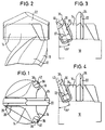
- FIGS. 1 to 4 A drilling tool according to the invention is shown in FIGS. 1 to 4.
- This contains a shaft 10, which has drill material removal grooves 12 is provided.
- a drill head 14 connects to the shaft 10.
- This is provided with three arms 16, 18, 20, the manner of a hollow-throat triangle are arranged. The one between two adjacent arms of the three arms 16, 18, 20 located free space is used to discharge the shredded drill material to the drill material discharge grooves 12.
- a crushing plate 22 is embedded, which is a side view seen gable-shaped (see Figure 2).
- the Crushing plate 22 is provided with two cutting edges 24, 26, of which the one on one side and the other on the other side of the median longitudinal plane the crushing plate 22 is arranged.
- the crushing plate 22 stands with its two radial ends over the outer circumference of the drill head 14 out.
- each shear pin has a circular cross section and is recorded in a receptacle 32 or 34, which also has a has circular cross section.
- the diameter of the two shear pins 28, 30 differ from one another; the breaking pin 28 has one Diameter D1, which is larger than the diameter D2 of the breaking pin 30 is.
- a diameter D1 of 8.2 mm can be used and the diameter D2 can be 6 mm.
- each breaking pin is oblique to the longitudinal axis of the Drilling tool aligned.
- This arrangement enables the breaking pins 28, 30 to be fixed in the material of the drill head anchor, since radially outside each receptacle 32, 34 is still sufficient Material is present on the drill head while the free ends of the breaking bolts 28 protruding from the arms 16, 18, 30 protrude beyond the outer circumference of the drill head.
- the arrangement is however, chosen so that the ends of the crushing plate 22 slightly wider protrude beyond the drill head as the outer edges of the Breaking pin. If, for example, the outer edges of the shear pins located on a circle with a diameter of 42 mm the ends of the crushing plate on a circle with a diameter of 42.37 mm.
- the two breaking pins 28, 30 are each with a breaking edge 36 or 38, which extends in a straight line. Every breaking edge extends in a direction other than a radial direction Direction, the two breaking edges are arranged so that see an imaginary extension intersects at a point that in the Middle plane of the crushing plate 22 lies in the area of the arm 20.
- each shear pin has one on its outside bevelled surface 40 and 42 provided. This prevents protruding Edges that could be damaged during drilling.
Landscapes
- Engineering & Computer Science (AREA)
- Mechanical Engineering (AREA)
- Drilling Tools (AREA)
- Milling Processes (AREA)
Applications Claiming Priority (4)
| Application Number | Priority Date | Filing Date | Title |
|---|---|---|---|
| DE19811887 | 1998-03-18 | ||
| DE1998111887 DE19811887A1 (de) | 1998-03-18 | 1998-03-18 | Hammerbohrwerkzeug |
| DE29816203U | 1998-09-09 | ||
| DE29816203U DE29816203U1 (de) | 1998-03-18 | 1998-09-09 | Bohrwerkzeug |
Publications (2)
| Publication Number | Publication Date |
|---|---|
| EP0943780A2 true EP0943780A2 (fr) | 1999-09-22 |
| EP0943780A3 EP0943780A3 (fr) | 2000-07-19 |
Family
ID=26044731
Family Applications (1)
| Application Number | Title | Priority Date | Filing Date |
|---|---|---|---|
| EP99104060A Withdrawn EP0943780A3 (fr) | 1998-03-18 | 1999-03-17 | Outil de forage |
Country Status (1)
| Country | Link |
|---|---|
| EP (1) | EP0943780A3 (fr) |
Cited By (2)
| Publication number | Priority date | Publication date | Assignee | Title |
|---|---|---|---|---|
| US6926104B2 (en) | 2001-08-01 | 2005-08-09 | Techmo Entwicklungs- Und Vertriebs Gmbh | Drill crown |
| US7258180B2 (en) | 2003-11-03 | 2007-08-21 | Illinois Tool Works Inc. | Rotary hammerdrill bit |
Citations (1)
| Publication number | Priority date | Publication date | Assignee | Title |
|---|---|---|---|---|
| DE29703363U1 (de) | 1997-02-25 | 1997-04-10 | Drebo Werkzeugfabrik Gmbh, 88361 Altshausen | Bohrer |
Family Cites Families (4)
| Publication number | Priority date | Publication date | Assignee | Title |
|---|---|---|---|---|
| DE3544433C2 (de) * | 1985-12-16 | 1995-12-14 | Hilti Ag | Gesteinsbohrer |
| US4716976A (en) * | 1986-10-28 | 1988-01-05 | Kennametal Inc. | Rotary percussion drill bit |
| DE4011441A1 (de) * | 1990-04-09 | 1991-10-10 | Hilti Ag | Gesteinsbohrer |
| US5224560A (en) * | 1990-10-30 | 1993-07-06 | Modular Engineering | Modular drill bit |
-
1999
- 1999-03-17 EP EP99104060A patent/EP0943780A3/fr not_active Withdrawn
Patent Citations (1)
| Publication number | Priority date | Publication date | Assignee | Title |
|---|---|---|---|---|
| DE29703363U1 (de) | 1997-02-25 | 1997-04-10 | Drebo Werkzeugfabrik Gmbh, 88361 Altshausen | Bohrer |
Cited By (2)
| Publication number | Priority date | Publication date | Assignee | Title |
|---|---|---|---|---|
| US6926104B2 (en) | 2001-08-01 | 2005-08-09 | Techmo Entwicklungs- Und Vertriebs Gmbh | Drill crown |
| US7258180B2 (en) | 2003-11-03 | 2007-08-21 | Illinois Tool Works Inc. | Rotary hammerdrill bit |
Also Published As
| Publication number | Publication date |
|---|---|
| EP0943780A3 (fr) | 2000-07-19 |
Similar Documents
| Publication | Publication Date | Title |
|---|---|---|
| DE102009006520B4 (de) | Mechanisches Spannelement und Spannsystem | |
| DE112011103744B4 (de) | Wechselhaltersystem für einen Meißel | |
| DE69825586T3 (de) | Schneidwerkzeuganordnung und austauschbarer schneidkopf dafür | |
| DE4032176C2 (de) | Scheibenschneider | |
| EP3439774B1 (fr) | Arbre de mélange | |
| DE3707798A1 (de) | Gesteinsbohrer | |
| DE19545647A1 (de) | Drehschlag-Wendelbohrer | |
| DE102018106558A1 (de) | Von vorn geladener, seitlich aktivierter, modularer bohrer | |
| EP1640095B1 (fr) | Outil de fraisage, plus particulièrement fraise à fileter | |
| DE1752026A1 (de) | Reversible Bohrlochraeumnadel | |
| DE2905363C2 (de) | Scherbolzenkupplung | |
| EP0943780A2 (fr) | Outil de forage | |
| EP1024247A1 (fr) | Outil de forage | |
| DE3941935C2 (de) | Spannschloß | |
| CH700315B1 (de) | Spannsystem mit einem Spannelement und einem Schlüssel zum Anziehen des Spannelements. | |
| DE29816203U1 (de) | Bohrwerkzeug | |
| EP0860837B1 (fr) | Isolateur et adapteur pour fils, bandes ou torons sous tension électrique pour monter et fabriquer des clôtures | |
| DE102019130415A1 (de) | Schutzkappe | |
| DE19545646A1 (de) | Drehschlag-Wendelbohrer | |
| EP4230883B1 (fr) | Elément d'entraînement, en particulier sous forme de vis | |
| DE202015106961U1 (de) | Werkzeug | |
| EP3805491B1 (fr) | Dispositif de fermeture | |
| EP0987398A1 (fr) | Foret | |
| DE202009005493U1 (de) | Zerkleinerungsmesser und Zerkleinerungsvorrichtung mit einem solchen | |
| DE2807120A1 (de) | Schneckenfraeser mit eingesetzten schneiden |
Legal Events
| Date | Code | Title | Description |
|---|---|---|---|
| PUAI | Public reference made under article 153(3) epc to a published international application that has entered the european phase |
Free format text: ORIGINAL CODE: 0009012 |
|
| AK | Designated contracting states |
Kind code of ref document: A2 Designated state(s): AT BE CH DE DK ES FI FR IT LI LU NL SE |
|
| AX | Request for extension of the european patent |
Free format text: AL;LT;LV;MK;RO;SI |
|
| PUAL | Search report despatched |
Free format text: ORIGINAL CODE: 0009013 |
|
| AK | Designated contracting states |
Kind code of ref document: A3 Designated state(s): AT BE CH CY DE DK ES FI FR GB GR IE IT LI LU MC NL PT SE |
|
| AX | Request for extension of the european patent |
Free format text: AL;LT;LV;MK;RO;SI |
|
| EL | Fr: translation of claims filed | ||
| 17P | Request for examination filed |
Effective date: 20001108 |
|
| AKX | Designation fees paid |
Free format text: AT BE CH DE DK ES FI FR IT LI LU NL SE |
|
| STAA | Information on the status of an ep patent application or granted ep patent |
Free format text: STATUS: THE APPLICATION IS DEEMED TO BE WITHDRAWN |
|
| 18D | Application deemed to be withdrawn |
Effective date: 20031002 |