EP0943783A2 - Boulon de fixation pour un outil de coupe cylindrique - Google Patents
Boulon de fixation pour un outil de coupe cylindrique Download PDFInfo
- Publication number
- EP0943783A2 EP0943783A2 EP99104692A EP99104692A EP0943783A2 EP 0943783 A2 EP0943783 A2 EP 0943783A2 EP 99104692 A EP99104692 A EP 99104692A EP 99104692 A EP99104692 A EP 99104692A EP 0943783 A2 EP0943783 A2 EP 0943783A2
- Authority
- EP
- European Patent Office
- Prior art keywords
- cutting body
- body according
- cutting
- bore
- bolt
- Prior art date
- Legal status (The legal status is an assumption and is not a legal conclusion. Google has not performed a legal analysis and makes no representation as to the accuracy of the status listed.)
- Withdrawn
Links
Images
Classifications
-
- E—FIXED CONSTRUCTIONS
- E21—EARTH OR ROCK DRILLING; MINING
- E21C—MINING OR QUARRYING
- E21C35/00—Details of, or accessories for, machines for slitting or completely freeing the mineral from the seam, not provided for in groups E21C25/00 - E21C33/00, E21C37/00 or E21C39/00
- E21C35/18—Mining picks; Holders therefor
- E21C35/19—Means for fixing picks or holders
- E21C35/193—Means for fixing picks or holders using bolts as main fixing elements
-
- E—FIXED CONSTRUCTIONS
- E21—EARTH OR ROCK DRILLING; MINING
- E21C—MINING OR QUARRYING
- E21C35/00—Details of, or accessories for, machines for slitting or completely freeing the mineral from the seam, not provided for in groups E21C25/00 - E21C33/00, E21C37/00 or E21C39/00
- E21C35/18—Mining picks; Holders therefor
- E21C35/188—Mining picks; Holders therefor characterised by adaptations to use an extraction tool
-
- E—FIXED CONSTRUCTIONS
- E21—EARTH OR ROCK DRILLING; MINING
- E21C—MINING OR QUARRYING
- E21C35/00—Details of, or accessories for, machines for slitting or completely freeing the mineral from the seam, not provided for in groups E21C25/00 - E21C33/00, E21C37/00 or E21C39/00
- E21C35/18—Mining picks; Holders therefor
- E21C35/19—Means for fixing picks or holders
- E21C35/191—Means for fixing picks or holders for fixing holders
-
- Y—GENERAL TAGGING OF NEW TECHNOLOGICAL DEVELOPMENTS; GENERAL TAGGING OF CROSS-SECTIONAL TECHNOLOGIES SPANNING OVER SEVERAL SECTIONS OF THE IPC; TECHNICAL SUBJECTS COVERED BY FORMER USPC CROSS-REFERENCE ART COLLECTIONS [XRACs] AND DIGESTS
- Y10—TECHNICAL SUBJECTS COVERED BY FORMER USPC
- Y10T—TECHNICAL SUBJECTS COVERED BY FORMER US CLASSIFICATION
- Y10T407/00—Cutters, for shaping
- Y10T407/19—Rotary cutting tool
- Y10T407/1906—Rotary cutting tool including holder [i.e., head] having seat for inserted tool
- Y10T407/1932—Rotary cutting tool including holder [i.e., head] having seat for inserted tool with means to fasten tool seat to holder
-
- Y—GENERAL TAGGING OF NEW TECHNOLOGICAL DEVELOPMENTS; GENERAL TAGGING OF CROSS-SECTIONAL TECHNOLOGIES SPANNING OVER SEVERAL SECTIONS OF THE IPC; TECHNICAL SUBJECTS COVERED BY FORMER USPC CROSS-REFERENCE ART COLLECTIONS [XRACs] AND DIGESTS
- Y10—TECHNICAL SUBJECTS COVERED BY FORMER USPC
- Y10T—TECHNICAL SUBJECTS COVERED BY FORMER US CLASSIFICATION
- Y10T407/00—Cutters, for shaping
- Y10T407/19—Rotary cutting tool
- Y10T407/1952—Having peripherally spaced teeth
-
- Y—GENERAL TAGGING OF NEW TECHNOLOGICAL DEVELOPMENTS; GENERAL TAGGING OF CROSS-SECTIONAL TECHNOLOGIES SPANNING OVER SEVERAL SECTIONS OF THE IPC; TECHNICAL SUBJECTS COVERED BY FORMER USPC CROSS-REFERENCE ART COLLECTIONS [XRACs] AND DIGESTS
- Y10—TECHNICAL SUBJECTS COVERED BY FORMER USPC
- Y10T—TECHNICAL SUBJECTS COVERED BY FORMER US CLASSIFICATION
- Y10T407/00—Cutters, for shaping
- Y10T407/22—Cutters, for shaping including holder having seat for inserted tool
- Y10T407/227—Cutters, for shaping including holder having seat for inserted tool with separate means to fasten tool seat to holder
-
- Y—GENERAL TAGGING OF NEW TECHNOLOGICAL DEVELOPMENTS; GENERAL TAGGING OF CROSS-SECTIONAL TECHNOLOGIES SPANNING OVER SEVERAL SECTIONS OF THE IPC; TECHNICAL SUBJECTS COVERED BY FORMER USPC CROSS-REFERENCE ART COLLECTIONS [XRACs] AND DIGESTS
- Y10—TECHNICAL SUBJECTS COVERED BY FORMER USPC
- Y10T—TECHNICAL SUBJECTS COVERED BY FORMER US CLASSIFICATION
- Y10T407/00—Cutters, for shaping
- Y10T407/22—Cutters, for shaping including holder having seat for inserted tool
- Y10T407/2272—Cutters, for shaping including holder having seat for inserted tool with separate means to fasten tool to holder
Definitions
- the invention relates to a roller-shaped cutting body, especially for a cutting machine or road milling machine, according to the preamble of claim 1.
- Such cutting bodies have on their outer surface in usually a large number arranged in uniform division Base body that, for example, a broaching auger or form a clearing spiral.
- Base body that, for example, a broaching auger or form a clearing spiral.
- every body is a chisel holder with a replaceable chisel connected or it is e.g. a suitable one Chisel directly without a chisel holder as an intermediate element used.
- a generic cutting body is from DE 43 22 402 C 2 known, in which the chisel holder with a plug-in approach designated shaft in a socket of the Basic body introduced and in the basic body with an in this screwed, over a hexagonal Tool holder actuable grub screw, which in a engages associated recess of the shaft of the chisel holder, is secured against being pulled out.
- This securing has the disadvantage that the internal thread of the extending through the base body and the hexagon socket of the grub screw serving as tool holder, especially in the case of large amounts of dust Cutting operation of the cutting body, susceptible to contamination is so that the fuse can be removed for replacement of the bit holder is difficult.
- the invention is therefore concerned with the problem of a to create generic cutting body, its securing simply built for the one or the chisel holder or the like, not susceptible to pollution and accordingly Needs is easy to solve.
- this problem is caused by a cutting body solved with the features of claim 1.
- the safety bolt is not a grub screw trained and according to the invention in the bore in the base body is held without threading or locking soiling-prone threads in the base body and with it the danger that this, with foreign bodies added, loosening the fuse and replacing the Chisel holder complicate.
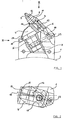
- Fig. 1 shows a base body 1 whose underside is concave is arched in a circular arc and thus the dashed adapts indicated outer surface 2 of the cutting body which the base body 1, for example, by a welded connection is attached.
- the basic body 1 has one Plug-in receptacle 3, into which a bit holder 4 molded shaft 5 is inserted.
- the chisel holder 4 includes a chisel receptacle 6, which the shaft part 7 of a chisel 8.
- On the bit head 9 facing Side of the chisel holder 6 is a contact surface 10 trained on which the chisel 8 with a collar 11th crashes.
- the chisel 8 is against being pulled out in the direction its axis 12 secured by a latch 13.
- a through hole extends through the base body 1 14, the inclusion of a safety bolt 15 serves.
- the shaft 5 of the bit holder 4 has one of the bore 14 in the base body 1 associated recess 16, which at the illustrated embodiment as a laterally open, all-round Ring groove is formed.
- the securing bolt 15 by the shaft 5 of the bit holder 4 at its recess 16 reaches behind in areas that the chisel holder 4 releases from the base body 1.
- the embodiment of the recess 16 is favorable as a completely circumferential ring groove.
- the bit holder 4 is then thereby against Twist ensured that he was dealing with a nasal Area 17 on an alignment surface 18 of the base body 1 supports.
- the bore 14 extends under a pointed Angle ⁇ to the longitudinal axis 19 of the bit holder 4.
- the fuse is formed as a clamp, the bolt 15 in the Bore 14 is held by an interference fit.
- the bore is completely smooth on the inside can be so that no dirt particles on their walls stick.
- the backup can also be used as Detent, for example in the form of a bayonet lock, be trained.
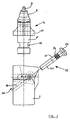
- the securing bolt 15 shown in FIG. 3 has one the insertion into the bore 14 facilitates conical Front part 20 and a rear part 21 with a cylindrical Lateral surface on.
- the outer surface partially elastically deformable, the elastic deformable area in the undeformed state an oversize opposite the bore 14, which causes the clamping.
- the sleeve 22 can be replaced be designed, for example, under easy expansion is pushed over the bolt 15.
- the bolt core in the area of the sleeve 22 can be a have reduced diameter, so that the upper and Form lower contact surfaces that prevent the Prevent sleeve 22 when it is pushed onto the bolt 15.
- an interchangeable sleeve 22 can be replaced when worn without the entire locking bolt 15 must be replaced. Is too it is possible to insert the sleeve 22 through a sleeve of larger outside diameter to replace if in the operation of the Cutting body play between the bore 14 or the Recess 16 of the chisel holder 4 and the securing bolt 15 should have trained.
- the safety bolt 15 shown has on its rear When installed, end the rear mouth opening 23 of the bore 14 covering head 24. Thereby there is a risk of contamination entering the Hole 14 further reduced.
- the safety bolt 15 during assembly until it stops in the Bore 14 are pressed in without the risk of to drive it through the bore 14.
- the locking pin 15 is from the opposite Mouth opening 26 with a suitable Tool driven out of the bore 14.
- the bolt head 24 can be used to release the fuse.
- it can have recesses into which engage a suitable tool and the safety bolt 15 can pull out.
Landscapes
- Engineering & Computer Science (AREA)
- Mining & Mineral Resources (AREA)
- Mechanical Engineering (AREA)
- Life Sciences & Earth Sciences (AREA)
- General Life Sciences & Earth Sciences (AREA)
- Geochemistry & Mineralogy (AREA)
- Geology (AREA)
- Percussive Tools And Related Accessories (AREA)
- Control And Other Processes For Unpacking Of Materials (AREA)
- Road Repair (AREA)
Applications Claiming Priority (2)
| Application Number | Priority Date | Filing Date | Title |
|---|---|---|---|
| DE29805007U DE29805007U1 (de) | 1998-03-19 | 1998-03-19 | Walzenförmiger Schneidkörper |
| DE29805007U | 1998-03-19 |
Publications (2)
| Publication Number | Publication Date |
|---|---|
| EP0943783A2 true EP0943783A2 (fr) | 1999-09-22 |
| EP0943783A3 EP0943783A3 (fr) | 2003-10-01 |
Family
ID=8054453
Family Applications (1)
| Application Number | Title | Priority Date | Filing Date |
|---|---|---|---|
| EP99104692A Withdrawn EP0943783A3 (fr) | 1998-03-19 | 1999-03-10 | Boulon de fixation pour un outil de coupe cylindrique |
Country Status (4)
| Country | Link |
|---|---|
| US (1) | US6183170B1 (fr) |
| EP (1) | EP0943783A3 (fr) |
| DE (1) | DE29805007U1 (fr) |
| PL (1) | PL332030A1 (fr) |
Families Citing this family (9)
| Publication number | Priority date | Publication date | Assignee | Title |
|---|---|---|---|---|
| DE10044369C2 (de) * | 2000-09-08 | 2003-03-27 | Michael Steinbrecher | Schnellwechselhaltersystem für Werkzeuge auf Walzen |
| US6481803B2 (en) * | 2001-01-16 | 2002-11-19 | Kennametal Inc. | Universal bit holder block connection surface |
| US7108212B2 (en) * | 2003-11-11 | 2006-09-19 | Keystone Engineering & Manufacturing Corporation | Angular tool and holding block |
| DE102004057302B4 (de) * | 2004-11-26 | 2011-01-13 | Wirtgen Gmbh | Meißelhalter |
| US7434890B2 (en) * | 2005-03-23 | 2008-10-14 | Boart Longyear Inc. | Vibratory milling machine having linear reciprocating motion |
| US8079647B2 (en) * | 2005-03-23 | 2011-12-20 | Longyear Tm, Inc. | Vibratory milling machine having linear reciprocating motion |
| US7338134B2 (en) * | 2005-11-23 | 2008-03-04 | Keystone Engineering & Manufacturing Corp. | Flighting and tool holder |
| USD681069S1 (en) * | 2012-07-31 | 2013-04-30 | Caterpillar Paving Products Inc. | Mounting block for paving apparatus |
| USD680560S1 (en) * | 2012-07-31 | 2013-04-23 | Caterpillar Paving Products Inc. | Deflector for paving apparatus |
Family Cites Families (13)
| Publication number | Priority date | Publication date | Assignee | Title |
|---|---|---|---|---|
| US530793A (en) * | 1894-12-11 | Matthew odgers | ||
| US3092374A (en) * | 1958-02-06 | 1963-06-04 | Cincinnati Mine Machinery Co | Resilient engagement device |
| US2965365A (en) * | 1958-04-14 | 1960-12-20 | Cincinnati Mine Machinery Co | Bit and resilient holding means therefor |
| US3285668A (en) * | 1963-11-20 | 1966-11-15 | Galion Jeffrey Mfg Co | Cutter bit holder |
| US3519309A (en) * | 1965-08-12 | 1970-07-07 | Kennametal Inc | Rotary cone bit retained by captive keeper ring |
| US3397012A (en) * | 1966-12-19 | 1968-08-13 | Cincinnati Mine Machinery Co | Cutter bits and means for mounting them |
| US3575467A (en) * | 1969-03-11 | 1971-04-20 | Carmet Co | Cutter bit and block |
| US4057294A (en) * | 1975-08-01 | 1977-11-08 | The Cincinnati Mine Machinery Company | Wedge arrangement for removably affixing a work tool or work tool holder to a base member on mining, road working or earth moving machinery, and the like |
| US4337980A (en) * | 1979-05-21 | 1982-07-06 | The Cincinnati Mine Machinery Company | Wedge arrangements and related means for mounting means, base members, and bits, and combinations thereof, for mining, road working, or earth moving machinery |
| US4915454A (en) * | 1986-11-04 | 1990-04-10 | Southern Philip W | Mining bit and holder |
| DE3927285A1 (de) * | 1989-08-18 | 1991-02-21 | Boart Hwf Gmbh & Co | Hobel- und schraemmeissel fuer gewinnungsmaschinen zum abbau von lagerstaetten |
| DE4322402C2 (de) * | 1993-07-06 | 1996-06-20 | Wirtgen Gmbh | Schneidkörper für eine Schrämmaschine |
| DE29803944U1 (de) * | 1998-03-06 | 1998-04-30 | DBT Deutsche Bergbau-Technik GmbH, 44534 Lünen | Meißelsicherung für einen Hobelmeißel |
-
1998
- 1998-03-19 DE DE29805007U patent/DE29805007U1/de not_active Expired - Lifetime
-
1999
- 1999-03-10 EP EP99104692A patent/EP0943783A3/fr not_active Withdrawn
- 1999-03-17 PL PL99332030A patent/PL332030A1/xx unknown
- 1999-03-19 US US09/273,298 patent/US6183170B1/en not_active Expired - Fee Related
Also Published As
| Publication number | Publication date |
|---|---|
| EP0943783A3 (fr) | 2003-10-01 |
| PL332030A1 (en) | 1999-09-27 |
| US6183170B1 (en) | 2001-02-06 |
| DE29805007U1 (de) | 1998-05-20 |
Similar Documents
| Publication | Publication Date | Title |
|---|---|---|
| DE102010025653B4 (de) | Rotations-Schneidwerkzeug | |
| DE60224252T2 (de) | Drehendes Werkzeug zur spanabhebenden Bearbeitung | |
| EP2318166B1 (fr) | Outil pour l'usinage par enlèvement de copeaux d'une pièce à usiner | |
| DE69709793T2 (de) | Bohrmeissel zu beaufschlagen einer formation | |
| DE29708384U1 (de) | Mit der Antriebswelle einer Drehmaschine kuppelbares Werkzeugsystem | |
| DE3026930A1 (de) | Keilanordnung und zugeordnete mittel fuer befestigungsvorrichtungen, traeger und meissel und derenkombinationen fuer den bergbau, strassenbau und erdbewegungsmaschinen | |
| DE29823512U1 (de) | Bohrfutter | |
| EP1579105A1 (fr) | Outil de havage | |
| DE8106316U1 (de) | Bohrwerkzeug | |
| EP0943783A2 (fr) | Boulon de fixation pour un outil de coupe cylindrique | |
| DE3712707A1 (de) | Messereinsatz | |
| DE10222048B4 (de) | Werkzeug und Verfahren zur Maschinenbearbeitung von Werkstücken | |
| EP1369603A1 (fr) | Elément de vis, et endroit de contact permettant de tourner la vis | |
| DE1427740A1 (de) | Geraet zum Eintreiben von Expansionshuelsen in Beton,Mauerwerk usw | |
| DE102011051584A1 (de) | Verfahren zur Lagerung eines Meißels sowie zugehörige Vorrichtung | |
| DE3900140C1 (fr) | ||
| DE19803998C2 (de) | Bohrer zur Herstellung von Bohrungen in Knochengewebe | |
| DE20306065U1 (de) | Walzenförmiger Schneidkörper | |
| WO1999024200A1 (fr) | Raccord rapide pour outils de foreuse a pointes de diamants, en particulier pour outils de foreuse a carottage (raccord rapide de couronne de forage) | |
| DE19711261A1 (de) | Kombi-Bohrwerkzeug | |
| DE102022105710A1 (de) | Schneidwerkzeug mit austauschbarem Schneideinsatz | |
| DE102023200289B4 (de) | Vorrichtung, welche ein Rotationswerkzeug aufweist, und Verfahren zum Befestigen oder Lösen eines Schneideinsatzes bei einer solchen Vorrichtung | |
| EP2754854B1 (fr) | Procédé de fixation d'un pic ainsi que dispositif correspondant | |
| DE3346440A1 (de) | Bohrfutter, insbesondere hammerbohrfutter | |
| DE10157787A1 (de) | Werkzeug für die spanabhebende Bearbeitung |
Legal Events
| Date | Code | Title | Description |
|---|---|---|---|
| PUAI | Public reference made under article 153(3) epc to a published international application that has entered the european phase |
Free format text: ORIGINAL CODE: 0009012 |
|
| AK | Designated contracting states |
Kind code of ref document: A2 Designated state(s): AT BE CH CY DE DK ES FI FR GB GR IE IT LI LU MC NL PT SE |
|
| AX | Request for extension of the european patent |
Free format text: AL;LT;LV;MK;RO;SI |
|
| PUAL | Search report despatched |
Free format text: ORIGINAL CODE: 0009013 |
|
| AK | Designated contracting states |
Kind code of ref document: A3 Designated state(s): AT BE CH CY DE DK ES FI FR GB GR IE IT LI LU MC NL PT SE |
|
| AX | Request for extension of the european patent |
Extension state: AL LT LV MK RO SI |
|
| AKX | Designation fees paid | ||
| REG | Reference to a national code |
Ref country code: DE Ref legal event code: 8566 |
|
| STAA | Information on the status of an ep patent application or granted ep patent |
Free format text: STATUS: THE APPLICATION IS DEEMED TO BE WITHDRAWN |
|
| 18D | Application deemed to be withdrawn |
Effective date: 20040402 |