EP0943789A2 - Dispositif pour la conversion de chaleur à température basse en énérgie électrique - Google Patents
Dispositif pour la conversion de chaleur à température basse en énérgie électrique Download PDFInfo
- Publication number
- EP0943789A2 EP0943789A2 EP99104986A EP99104986A EP0943789A2 EP 0943789 A2 EP0943789 A2 EP 0943789A2 EP 99104986 A EP99104986 A EP 99104986A EP 99104986 A EP99104986 A EP 99104986A EP 0943789 A2 EP0943789 A2 EP 0943789A2
- Authority
- EP
- European Patent Office
- Prior art keywords
- container
- pressure
- containers
- lines
- heat
- Prior art date
- Legal status (The legal status is an assumption and is not a legal conclusion. Google has not performed a legal analysis and makes no representation as to the accuracy of the status listed.)
- Granted
Links
- 238000001816 cooling Methods 0.000 claims abstract description 5
- 239000002826 coolant Substances 0.000 claims description 5
- 238000010438 heat treatment Methods 0.000 claims description 2
- 239000012530 fluid Substances 0.000 claims 1
- 239000007789 gas Substances 0.000 description 36
- 238000012360 testing method Methods 0.000 description 14
- XLYOFNOQVPJJNP-UHFFFAOYSA-N water Substances O XLYOFNOQVPJJNP-UHFFFAOYSA-N 0.000 description 9
- 238000000034 method Methods 0.000 description 8
- CURLTUGMZLYLDI-UHFFFAOYSA-N Carbon dioxide Chemical compound O=C=O CURLTUGMZLYLDI-UHFFFAOYSA-N 0.000 description 6
- 238000006243 chemical reaction Methods 0.000 description 6
- 229910002092 carbon dioxide Inorganic materials 0.000 description 3
- 239000001569 carbon dioxide Substances 0.000 description 3
- 239000007788 liquid Substances 0.000 description 3
- 230000005611 electricity Effects 0.000 description 2
- TZCXTZWJZNENPQ-UHFFFAOYSA-L barium sulfate Chemical group [Ba+2].[O-]S([O-])(=O)=O TZCXTZWJZNENPQ-UHFFFAOYSA-L 0.000 description 1
- 229910052799 carbon Inorganic materials 0.000 description 1
- 239000000498 cooling water Substances 0.000 description 1
- 230000001419 dependent effect Effects 0.000 description 1
- 238000013461 design Methods 0.000 description 1
- 238000002474 experimental method Methods 0.000 description 1
- 238000005338 heat storage Methods 0.000 description 1
- 239000008236 heating water Substances 0.000 description 1
- 239000002440 industrial waste Substances 0.000 description 1
- 239000007791 liquid phase Substances 0.000 description 1
- 239000000203 mixture Substances 0.000 description 1
- 230000035515 penetration Effects 0.000 description 1
- 239000012429 reaction media Substances 0.000 description 1
- 239000002352 surface water Substances 0.000 description 1
- 210000001550 testis Anatomy 0.000 description 1
- 238000012549 training Methods 0.000 description 1
- 238000012546 transfer Methods 0.000 description 1
- 239000002918 waste heat Substances 0.000 description 1
Images


Classifications
-
- F—MECHANICAL ENGINEERING; LIGHTING; HEATING; WEAPONS; BLASTING
- F01—MACHINES OR ENGINES IN GENERAL; ENGINE PLANTS IN GENERAL; STEAM ENGINES
- F01K—STEAM ENGINE PLANTS; STEAM ACCUMULATORS; ENGINE PLANTS NOT OTHERWISE PROVIDED FOR; ENGINES USING SPECIAL WORKING FLUIDS OR CYCLES
- F01K25/00—Plants or engines characterised by use of special working fluids, not otherwise provided for; Plants operating in closed cycles and not otherwise provided for
- F01K25/08—Plants or engines characterised by use of special working fluids, not otherwise provided for; Plants operating in closed cycles and not otherwise provided for using special vapours
- F01K25/10—Plants or engines characterised by use of special working fluids, not otherwise provided for; Plants operating in closed cycles and not otherwise provided for using special vapours the vapours being cold, e.g. ammonia, carbon dioxide, ether
- F01K25/103—Carbon dioxide
-
- F—MECHANICAL ENGINEERING; LIGHTING; HEATING; WEAPONS; BLASTING
- F02—COMBUSTION ENGINES; HOT-GAS OR COMBUSTION-PRODUCT ENGINE PLANTS
- F02C—GAS-TURBINE PLANTS; AIR INTAKES FOR JET-PROPULSION PLANTS; CONTROLLING FUEL SUPPLY IN AIR-BREATHING JET-PROPULSION PLANTS
- F02C1/00—Gas-turbine plants characterised by the use of hot gases or unheated pressurised gases, as the working fluid
- F02C1/04—Gas-turbine plants characterised by the use of hot gases or unheated pressurised gases, as the working fluid the working fluid being heated indirectly
- F02C1/05—Gas-turbine plants characterised by the use of hot gases or unheated pressurised gases, as the working fluid the working fluid being heated indirectly characterised by the type or source of heat, e.g. using nuclear or solar energy
-
- F—MECHANICAL ENGINEERING; LIGHTING; HEATING; WEAPONS; BLASTING
- F02—COMBUSTION ENGINES; HOT-GAS OR COMBUSTION-PRODUCT ENGINE PLANTS
- F02C—GAS-TURBINE PLANTS; AIR INTAKES FOR JET-PROPULSION PLANTS; CONTROLLING FUEL SUPPLY IN AIR-BREATHING JET-PROPULSION PLANTS
- F02C1/00—Gas-turbine plants characterised by the use of hot gases or unheated pressurised gases, as the working fluid
- F02C1/04—Gas-turbine plants characterised by the use of hot gases or unheated pressurised gases, as the working fluid the working fluid being heated indirectly
- F02C1/10—Closed cycles
Definitions
- the invention relates to a device for converting so-called low temperature heat in electrical energy.
- n is the MOL number of the gas in volume V
- R is the gas constant.
- all known devices use the absolute temperature to keep the internal energy of the gas high.
- the present invention uses absolute pressure to maintain the internal energy of the gas by doing the following: In the two pressure vessels coupled together according to the invention, gas is compressed to a high absolute pressure and then heat is supplied to one of these pressure vessels, as a result of which the gas pressure is further increased therein. The second pressure vessel is cooled at the same time, ie there is a relative pressure difference between the two pressure vessels which can be used to drive a work machine which in turn drives an electric generator.
- gas such as carbon dioxide
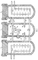
- Both pressure vessels 1, 2 are closed pressure-tight with caps 5, 6.
- Heat exchangers 7, 9 are arranged in the containers 1, 2, the heat exchanger 7 being connected via line 8 to an external heat source (not shown) and the heat exchanger 9 via line 10 to a cooling source (likewise not shown).
- a work machine 11 is located in the container 2, preferably in the form of a gas turbine, which is coupled to an electrical generator 12.
- a cable penetration element 14 for control and power lines 15, 16, 17 is provided in a pressure-tight manner, but could also be arranged in the cover 6.
- an electrically driven pump 13 for conveying liquefied gas, which pumps the resulting liquefied gas from the container 2 into the container 1 through line 18.
- Carbon dioxide is used as the thermodynamic working medium, the critical temperature of which is 31 ° C and the critical pressure of which is 72.9 atm and which is known to liquefy at a pressure of 72.9 atm and at a temperature which is lower than 31 ° C.
- the critical temperature of which is 31 ° C
- the critical pressure of which is 72.9 atm and which is known to liquefy at a pressure of 72.9 atm and at a temperature which is lower than 31 ° C.
- the gas initially introduced through the connecting piece 3, 4 is compressed to a higher absolute pressure than the critical pressure, and at the same time the temperature is kept slightly above the critical temperature of 31 ° C. in both containers 1, 2 by means of the heat exchangers 7, 9 .
- the data in Table 1 show that both pressure vessels 1, 2 have a volume of 10 m 3 .
- the data of Test No. 1 show that the working temperature ⁇ T, that is, the difference between tanks 1 and 2, is 50 ° C.
- the absolute pressure of the CO 2 is 200 atm.
- part of the CO 2 condenses and collects as liquid gas at the bottom of the container 2.
- the pump 13 pumps the liquid back into container 1.
- the temperature is above the critical temperature of the CO 2 and therefore the liquid gas supplied evaporates.
- Test No. 1 in Table 1 shows the heat storage capacity of the gas in container 1, the 35,692 kilocalories or Is 149 megajoules. According to experimental results half of the amount of energy stored every 20 minutes of which converted into electrical energy. Technically, one is such result solely from the quality of the Heat exchanger 7, 9 dependent. According to Test No. 1, pro Hour and 1,494 kilowatt hours of electrical energy per day generated. 36 liters of warm water flow through every minute the heat exchanger 7 in tank 1. The result in test no. 1 shows that the efficiency of the device is in the range of 50% lies. In Table 1 there are further numerical examples listed. The data in tests Nos.
- the performance of the device increases with an increase in the temperature difference between the gas in the containers 1, 2.
- the data in Table 1 are to be used such that a higher absolute pressure in both containers 1, 2 is necessary when the temperature difference between the heat transfer medium and the coolant is low is.
- even low temperature heat can be economically converted into electrical energy with a difference of only 10 ° C.
- the problem of the functionality of suitable machines at high pressures is solved by that the working machine 11, the electric generator 12 and the pump 13 are arranged in the pressure vessel 2. 1, care must be taken that the electrical energy output and the heat energy supply are timed so that the CO 2 liquefaction is always kept optimally above the CO 2 pressure, which can be easily achieved with the electronic control options available today.
- an additional gas such as dry air
- a gas mixture works according to the thermodynamic rules of the partial pressure. For example, if the partial pressure of CO 2 is 200 atm and the partial pressure of dry air is 800 atm, this means that there is an absolute pressure of 1,000 atm in container 2. The air remains in the container 2 as a gas cushion and is not involved in the work process, and not because the air is not liquefied and is always above the liquid phase of the CO 2 in the container 2.
- FIG. 2 If one does not want to operate the device at extreme absolute pressure P, an embodiment according to FIG. 2 can be considered.
- two heatable containers 21, 22 are connected in series via hot water pipes 25, 26, 27, as a result of which the heat is released to the gas in two temperature stages.
- the still warm water from the heat exchanger 7 in the container 21 flows further into the container 22 and releases the heat to the gas located there.
- the cooled container 23 is connected via lines 28, 29 to the container 21 in the same way as shown in Fig.1.
- the coolant lines of the containers 23, 24 are designated 32, 33.
- the efficiency increases in the range of 0.6.
- the working medium of the device according to FIGS. 1 and 2 does not necessarily have to be carbon dioxide, ie there are also many other gases whose critical temperature is relatively high and whose critical pressure is relatively low, which is not necessary to list in detail, since it is known.
- FIG. 3 the cheapest and simplest equipment would be Air, the critical temperature of which is at -150 ° C lies. Therefore, for the use of air as a resource a device according to FIG. 3 is provided.
- the Containers A, B heat exchanger 34,35 arranged, and in the container C is the work machine 36 with its electrical Generator 37, the container C by a in Fig. 3rd Heat exchanger, not shown, is cooled.
- marriage the Duty cycle begins, all three containers A, B, C are through the connector 38 on the container C filled with air and on compresses the desired absolute pressure. That's what they're for Valves 39, 40 and 45 open.
- the container A is cooled by means of the heat exchanger 34, and the container B is brought to the desired temperature by means of the heat exchanger 35.
- Test No. 1 in Table 2 illustrates the relevant data for this
- the work cycle begins.
- the valves 39, 40, 42, 43 and 45 are closed.
- the air in container A is then heated by means of heat exchanger 34.
- the air in container B is cooled by heat exchanger 35.
- the temperature difference between the tanks A, B results in a relative air pressure ⁇ P AB .
- Test No. 2 in Table 2 illustrates an example in which the air temperature in tank A is 50 ° C higher than in tank B.
- the relative average working pressure ⁇ P d is 33 atm.
- the stored heat is 31,230 kcal.
- the energy thus present is converted into mechanical work in the work machine 36 and this is then converted into electrical energy by the generator 37.
- the outlet of the working machine 36 flows through the air outlet 20 into the container C and through the valve 39 and line 41 to the container B.
- the air pressure in the container A drops and in the container B the air pressure increases.
- the valves 42, 39 are closed and the valve 45 in the line 44 is opened for a short time.
- valve 45 After opening the valve 45, the residual pressure in container A is equalized with the pressure in container B, the valve 45 is closed and the operation is now carried out in the opposite direction, ie, the air in the container B is heated and simultaneously by the heat exchanger 35 the air in container A is cooled by heat exchanger 34.
- Test No. 3 Corresponding numerical data for this operation are listed in Test No. 3, Table 2. This process takes approximately 15 minutes, ie the device according to FIG. 3 does not supply any current during this pause. After approximately 15 minutes, the valves 43, 40 are opened and air flows from the container B through the working machine 36 and its outlet 20 into the container C and from the container C through the opened valve 40 to the container A. Test No. 3 in Table 2 shows all the technical data associated with this conversion process. After equalization of the residual pressure via line 44 and after closing valves 43, 40 and 45, the same process begins in the opposite direction. The technical data in Table 2 show that the operations in this device always change direction.
- the containers designated A, B and C in FIG. 4 are the same as in FIG. 3, however, container A 1 and container B 1 are additionally connected to container C with corresponding lines 41.
- a line 44 (as in the example according to FIG. 3) is also arranged between the containers A and B or A 1 and B 1 , which serves for the residual pressure compensation.
- Such a device enables continuous operation without the above-mentioned pause and continuously supplies electricity.
- the container A 1 is heated and the container B 1 is cooled.
- the containers A, B are disconnected from the container C and the containers A 1 and B 1 are connected to the container C, and the air flows in the opposite direction. All of this can also be controlled electronically without further notice, which requires no special explanation.
- Fig. 4 illustrates that heating water through line 46 through the Heat exchanger can flow into tank B.
- Valves 48 are open and valves 49 are closed.
- the coolant through line 47 to the heat exchanger (heat exchangers are not shown here) passed in container B.
- the valves 49 are open and the valves 48 closed. Reservoirs for heating and Cooling media are not shown in Fig. 4.
- Cable routings are only to be understood in principle, i.e., these could also largely be covered by the cover 5.6 are performed, including those for the operation of the facility necessary work units, provided this is the constructive Allow conditions, arranged inside the cover 6 and can be linked to the lines accordingly.
- FIGS. 2 to 4 have only been chosen to differ from those in FIG. 1 for reasons of clarity, but are to be understood in each case as appropriate.
Landscapes
- Engineering & Computer Science (AREA)
- Chemical & Material Sciences (AREA)
- Combustion & Propulsion (AREA)
- Mechanical Engineering (AREA)
- General Engineering & Computer Science (AREA)
- Sustainable Development (AREA)
- Life Sciences & Earth Sciences (AREA)
- High Energy & Nuclear Physics (AREA)
- Physics & Mathematics (AREA)
- Sustainable Energy (AREA)
- Chemical Kinetics & Catalysis (AREA)
- Filling Or Discharging Of Gas Storage Vessels (AREA)
- Gas Or Oil Filled Cable Accessories (AREA)
- Inorganic Insulating Materials (AREA)
- Heat-Pump Type And Storage Water Heaters (AREA)
- Engine Equipment That Uses Special Cycles (AREA)
Applications Claiming Priority (2)
| Application Number | Priority Date | Filing Date | Title |
|---|---|---|---|
| DE19811800 | 1998-03-18 | ||
| DE19811800A DE19811800A1 (de) | 1998-03-18 | 1998-03-18 | Vorrichtung zur Umwandlung von Niedertemperaturwärme in elektrische Energie |
Publications (3)
| Publication Number | Publication Date |
|---|---|
| EP0943789A2 true EP0943789A2 (fr) | 1999-09-22 |
| EP0943789A3 EP0943789A3 (fr) | 2001-11-28 |
| EP0943789B1 EP0943789B1 (fr) | 2004-10-20 |
Family
ID=7861358
Family Applications (1)
| Application Number | Title | Priority Date | Filing Date |
|---|---|---|---|
| EP99104986A Expired - Lifetime EP0943789B1 (fr) | 1998-03-18 | 1999-03-12 | Dispositif pour la conversion de chaleur à température basse en énergie électrique |
Country Status (3)
| Country | Link |
|---|---|
| EP (1) | EP0943789B1 (fr) |
| AT (1) | ATE280321T1 (fr) |
| DE (2) | DE19811800A1 (fr) |
Cited By (1)
| Publication number | Priority date | Publication date | Assignee | Title |
|---|---|---|---|---|
| WO2008040475A1 (fr) | 2006-09-29 | 2008-04-10 | Tdc Trade, Development & Construction Ltd. | Dispositif pour obtenir de l'énergie électrique à partir de chaleur à basse température ou de chaleur dissipée |
Families Citing this family (3)
| Publication number | Priority date | Publication date | Assignee | Title |
|---|---|---|---|---|
| DE202010013455U1 (de) | 2010-09-23 | 2010-12-02 | Ginzel, Lothar, Dipl.-Ing. | Elektrische Maschine |
| DE102010046951A1 (de) * | 2010-09-27 | 2012-03-29 | Förderverein dream4life e.V. | Aggregat zur Erzeugung eines Arbeitsdruckers eines Arbeitsmediums, welches keine feste Gitterstruktur aufweist, ohne mechanische Verdichtung |
| CN102094688A (zh) * | 2010-12-22 | 2011-06-15 | 唐毓 | 低热能驱动装置 |
Family Cites Families (5)
| Publication number | Priority date | Publication date | Assignee | Title |
|---|---|---|---|---|
| US3210254A (en) * | 1961-02-10 | 1965-10-05 | Gen Dynamics Corp | Heat extraction system for a nuclear reactor |
| FR1434435A (fr) * | 1965-03-08 | 1966-04-08 | Fleur Corp | Ensemble de turbomachines |
| GB1275756A (en) * | 1969-10-25 | 1972-05-24 | Rolls Royce | Improvements in or relating to closed-cycle gas turbine engine power plants |
| JPS5487314A (en) * | 1977-12-23 | 1979-07-11 | Texaco Development Corp | Power generation method and apparatus |
| US4257846A (en) * | 1978-01-19 | 1981-03-24 | Westinghouse Electric Corp. | Bi-brayton power generation with a gas-cooled nuclear reactor |
-
1998
- 1998-03-18 DE DE19811800A patent/DE19811800A1/de not_active Withdrawn
-
1999
- 1999-03-12 AT AT99104986T patent/ATE280321T1/de not_active IP Right Cessation
- 1999-03-12 DE DE59910874T patent/DE59910874D1/de not_active Expired - Lifetime
- 1999-03-12 EP EP99104986A patent/EP0943789B1/fr not_active Expired - Lifetime
Non-Patent Citations (1)
| Title |
|---|
| None |
Cited By (1)
| Publication number | Priority date | Publication date | Assignee | Title |
|---|---|---|---|---|
| WO2008040475A1 (fr) | 2006-09-29 | 2008-04-10 | Tdc Trade, Development & Construction Ltd. | Dispositif pour obtenir de l'énergie électrique à partir de chaleur à basse température ou de chaleur dissipée |
Also Published As
| Publication number | Publication date |
|---|---|
| ATE280321T1 (de) | 2004-11-15 |
| DE19811800A1 (de) | 1999-09-23 |
| EP0943789B1 (fr) | 2004-10-20 |
| DE59910874D1 (de) | 2004-11-25 |
| EP0943789A3 (fr) | 2001-11-28 |
Similar Documents
| Publication | Publication Date | Title |
|---|---|---|
| EP3186506B1 (fr) | Dispositif et procédé de stockage d'énergie | |
| DE69311040T2 (de) | Kryogenische Behandlungsanlage, insbesondere für die Lufttrennung | |
| EP0021302B1 (fr) | Centrale thermique alimentée par une source de chaleur géothermique | |
| WO2013110375A2 (fr) | Dispositif et procédé de production d'énergie électrique | |
| DE102012217929A1 (de) | Kraft-Wärme-Kraftwerk und Verfahren zum Betrieb eines Kraft-Wärme-Kraftwerks | |
| DE2046078A1 (de) | Einrichtung zum Regeln des Gasdrucks in einem geschlossenen Gaskreislauf | |
| EP0943789B1 (fr) | Dispositif pour la conversion de chaleur à température basse en énergie électrique | |
| EP2745060A2 (fr) | Module de chauffage/refroidissement compact et utilisation d'un module de chauffage/refroidissement compact | |
| EP2362935A2 (fr) | Procede et dispositif de recuperation d'energie thermique, notamment pour la production de courant electrique | |
| DE1426975A1 (de) | Verfahren und Vorrichtung zum Erzeugen tiefer Temperaturen | |
| DE10126403A1 (de) | Kraftstation mit einem CO2-Kreislauf | |
| EP3106763A1 (fr) | Ballon d'eau chaude sanitaire et installation de distribution d'eau chaude dotee d'un ballon d'eau chaude sanitaire | |
| DE19749714C2 (de) | Vorrichtung zur Simulation eines Wasser-Dampfkreislaufes von Wärmekraftwerken in Verbindung mit einer leittechnischen Anlage für die Ausbildung von Prozeßleitelektronikern | |
| DE102007052259A1 (de) | Kraftstoffversorgungseinrichtung für ein mit Wasserstoff zu betreibendes Kraftfahrzeug | |
| EP2159474B1 (fr) | Préparation de dioxyde de carbone | |
| DE102007062342B4 (de) | Verfahren und Anordnung zur Erhöhung des Temperaturniveaus im Kreislauf solarthermischer Anlagen oder Blockheizkraftwerke | |
| EP3787964A1 (fr) | Système modulaire d'alimentation électrique, dispositif d'alimentation électrique et procédé d'alimentation électrique d'une embarcation | |
| DE102013202285A1 (de) | Verfahren und Vorrichtung zur Erzeugung von Energie, insbesondere elektrischer Energie | |
| EP2069623B1 (fr) | Dispositif pour obtenir de l'energie electrique à partir de chaleur à basse temperature ou de chaleur dissipee | |
| DE1503276C3 (de) | Antriebsanlage mit Flüssigkeitsturbine | |
| DE3019471A1 (de) | Verfahren zum anheben von waermeenergie auf ein hoeheres temperaturniveau sowie vorrichtung zur durchfuehrung des verfahrens | |
| DE102014002336A1 (de) | Verfahren und Vorrichtung zur Erzeugung von Energie, insbesondere elektrischer Energie | |
| EP2326821A2 (fr) | Machine thermique et procédé permettant de la faire fonctionner | |
| DE19845739A1 (de) | Wärmekraftwerk mit Flüssigkeits/Gas-Lösung, insbesondere Wasser/Ammoniak-Lösung | |
| DE102011014108A1 (de) | Verfahren zur Gewinnung von elektrischer Energie aus Meereswärme |
Legal Events
| Date | Code | Title | Description |
|---|---|---|---|
| PUAI | Public reference made under article 153(3) epc to a published international application that has entered the european phase |
Free format text: ORIGINAL CODE: 0009012 |
|
| AK | Designated contracting states |
Kind code of ref document: A2 Designated state(s): AT BE CH CY DE DK ES FI FR GB GR IE IT LI LU MC NL PT SE Kind code of ref document: A2 Designated state(s): AT CH DE DK FR IT LI NL SE |
|
| AX | Request for extension of the european patent |
Free format text: AL;LT;LV;MK;RO;SI |
|
| RAP1 | Party data changed (applicant data changed or rights of an application transferred) |
Owner name: FUET FORSCHUNGS- UND ENTWICKLUNGSGES. TEMPLIN MBH |
|
| RIN1 | Information on inventor provided before grant (corrected) |
Inventor name: IMRIS, PAVEL DR. |
|
| PUAL | Search report despatched |
Free format text: ORIGINAL CODE: 0009013 |
|
| AK | Designated contracting states |
Kind code of ref document: A3 Designated state(s): AT BE CH CY DE DK ES FI FR GB GR IE IT LI LU MC NL PT SE |
|
| AX | Request for extension of the european patent |
Free format text: AL;LT;LV;MK;RO;SI |
|
| AKX | Designation fees paid | ||
| REG | Reference to a national code |
Ref country code: DE Ref legal event code: 8566 |
|
| 17P | Request for examination filed |
Effective date: 20020819 |
|
| RBV | Designated contracting states (corrected) |
Designated state(s): AT CH DE DK FR IT LI NL SE |
|
| GRAP | Despatch of communication of intention to grant a patent |
Free format text: ORIGINAL CODE: EPIDOSNIGR1 |
|
| GRAS | Grant fee paid |
Free format text: ORIGINAL CODE: EPIDOSNIGR3 |
|
| GRAL | Information related to payment of fee for publishing/printing deleted |
Free format text: ORIGINAL CODE: EPIDOSDIGR3 |
|
| GRAS | Grant fee paid |
Free format text: ORIGINAL CODE: EPIDOSNIGR3 |
|
| GRAA | (expected) grant |
Free format text: ORIGINAL CODE: 0009210 |
|
| AK | Designated contracting states |
Kind code of ref document: B1 Designated state(s): AT CH DE DK FR IT LI NL SE |
|
| PG25 | Lapsed in a contracting state [announced via postgrant information from national office to epo] |
Ref country code: NL Free format text: LAPSE BECAUSE OF FAILURE TO SUBMIT A TRANSLATION OF THE DESCRIPTION OR TO PAY THE FEE WITHIN THE PRESCRIBED TIME-LIMIT Effective date: 20041020 Ref country code: IT Free format text: LAPSE BECAUSE OF FAILURE TO SUBMIT A TRANSLATION OF THE DESCRIPTION OR TO PAY THE FEE WITHIN THE PRESCRIBED TIME-LIMIT;WARNING: LAPSES OF ITALIAN PATENTS WITH EFFECTIVE DATE BEFORE 2007 MAY HAVE OCCURRED AT ANY TIME BEFORE 2007. THE CORRECT EFFECTIVE DATE MAY BE DIFFERENT FROM THE ONE RECORDED. Effective date: 20041020 Ref country code: FR Free format text: LAPSE BECAUSE OF FAILURE TO SUBMIT A TRANSLATION OF THE DESCRIPTION OR TO PAY THE FEE WITHIN THE PRESCRIBED TIME-LIMIT Effective date: 20041020 |
|
| REG | Reference to a national code |
Ref country code: CH Ref legal event code: EP |
|
| REF | Corresponds to: |
Ref document number: 59910874 Country of ref document: DE Date of ref document: 20041125 Kind code of ref document: P |
|
| PG25 | Lapsed in a contracting state [announced via postgrant information from national office to epo] |
Ref country code: SE Free format text: LAPSE BECAUSE OF FAILURE TO SUBMIT A TRANSLATION OF THE DESCRIPTION OR TO PAY THE FEE WITHIN THE PRESCRIBED TIME-LIMIT Effective date: 20050120 Ref country code: DK Free format text: LAPSE BECAUSE OF FAILURE TO SUBMIT A TRANSLATION OF THE DESCRIPTION OR TO PAY THE FEE WITHIN THE PRESCRIBED TIME-LIMIT Effective date: 20050120 |
|
| PG25 | Lapsed in a contracting state [announced via postgrant information from national office to epo] |
Ref country code: AT Free format text: LAPSE BECAUSE OF NON-PAYMENT OF DUE FEES Effective date: 20050312 |
|
| PG25 | Lapsed in a contracting state [announced via postgrant information from national office to epo] |
Ref country code: LI Free format text: LAPSE BECAUSE OF NON-PAYMENT OF DUE FEES Effective date: 20050331 Ref country code: CH Free format text: LAPSE BECAUSE OF NON-PAYMENT OF DUE FEES Effective date: 20050331 |
|
| NLV1 | Nl: lapsed or annulled due to failure to fulfill the requirements of art. 29p and 29m of the patents act | ||
| PLBE | No opposition filed within time limit |
Free format text: ORIGINAL CODE: 0009261 |
|
| STAA | Information on the status of an ep patent application or granted ep patent |
Free format text: STATUS: NO OPPOSITION FILED WITHIN TIME LIMIT |
|
| 26N | No opposition filed |
Effective date: 20050721 |
|
| REG | Reference to a national code |
Ref country code: CH Ref legal event code: PL |
|
| EN | Fr: translation not filed | ||
| PGFP | Annual fee paid to national office [announced via postgrant information from national office to epo] |
Ref country code: DE Payment date: 20110426 Year of fee payment: 13 |
|
| REG | Reference to a national code |
Ref country code: DE Ref legal event code: R119 Ref document number: 59910874 Country of ref document: DE Effective date: 20121002 |
|
| PG25 | Lapsed in a contracting state [announced via postgrant information from national office to epo] |
Ref country code: DE Free format text: LAPSE BECAUSE OF NON-PAYMENT OF DUE FEES Effective date: 20121002 |