EP0943796A2 - Filtre à liquide pour purifier du carburant - Google Patents
Filtre à liquide pour purifier du carburant Download PDFInfo
- Publication number
- EP0943796A2 EP0943796A2 EP98119364A EP98119364A EP0943796A2 EP 0943796 A2 EP0943796 A2 EP 0943796A2 EP 98119364 A EP98119364 A EP 98119364A EP 98119364 A EP98119364 A EP 98119364A EP 0943796 A2 EP0943796 A2 EP 0943796A2
- Authority
- EP
- European Patent Office
- Prior art keywords
- liquid filter
- filter according
- channel
- connection
- end cap
- Prior art date
- Legal status (The legal status is an assumption and is not a legal conclusion. Google has not performed a legal analysis and makes no representation as to the accuracy of the status listed.)
- Granted
Links
- 239000007788 liquid Substances 0.000 title claims abstract description 49
- 239000000446 fuel Substances 0.000 title claims abstract description 12
- 238000001914 filtration Methods 0.000 title 1
- XLYOFNOQVPJJNP-UHFFFAOYSA-N water Substances O XLYOFNOQVPJJNP-UHFFFAOYSA-N 0.000 claims abstract description 24
- 238000003860 storage Methods 0.000 claims abstract description 16
- 238000010438 heat treatment Methods 0.000 claims description 11
- 230000008719 thickening Effects 0.000 claims description 11
- 238000007789 sealing Methods 0.000 claims description 7
- 238000007373 indentation Methods 0.000 claims description 6
- 238000004140 cleaning Methods 0.000 claims description 5
- 238000005485 electric heating Methods 0.000 claims description 2
- 230000007704 transition Effects 0.000 claims 1
- NJPPVKZQTLUDBO-UHFFFAOYSA-N novaluron Chemical compound C1=C(Cl)C(OC(F)(F)C(OC(F)(F)F)F)=CC=C1NC(=O)NC(=O)C1=C(F)C=CC=C1F NJPPVKZQTLUDBO-UHFFFAOYSA-N 0.000 abstract 2
- 239000012530 fluid Substances 0.000 abstract 1
- 239000002283 diesel fuel Substances 0.000 description 5
- 238000002347 injection Methods 0.000 description 4
- 239000007924 injection Substances 0.000 description 4
- 238000010276 construction Methods 0.000 description 3
- 230000008901 benefit Effects 0.000 description 2
- 238000009434 installation Methods 0.000 description 2
- 238000000926 separation method Methods 0.000 description 2
- 230000004323 axial length Effects 0.000 description 1
- 230000008859 change Effects 0.000 description 1
- 230000001419 dependent effect Effects 0.000 description 1
- 238000011161 development Methods 0.000 description 1
- 230000018109 developmental process Effects 0.000 description 1
- 230000002349 favourable effect Effects 0.000 description 1
- 238000004519 manufacturing process Methods 0.000 description 1
- 239000002184 metal Substances 0.000 description 1
- 238000011144 upstream manufacturing Methods 0.000 description 1
- 238000003466 welding Methods 0.000 description 1
Images


Classifications
-
- B—PERFORMING OPERATIONS; TRANSPORTING
- B01—PHYSICAL OR CHEMICAL PROCESSES OR APPARATUS IN GENERAL
- B01D—SEPARATION
- B01D29/00—Filters with filtering elements stationary during filtration, e.g. pressure or suction filters, not covered by groups B01D24/00 - B01D27/00; Filtering elements therefor
- B01D29/96—Filters with filtering elements stationary during filtration, e.g. pressure or suction filters, not covered by groups B01D24/00 - B01D27/00; Filtering elements therefor in which the filtering elements are moved between filtering operations; Particular measures for removing or replacing the filtering elements; Transport systems for filters
-
- B—PERFORMING OPERATIONS; TRANSPORTING
- B01—PHYSICAL OR CHEMICAL PROCESSES OR APPARATUS IN GENERAL
- B01D—SEPARATION
- B01D29/00—Filters with filtering elements stationary during filtration, e.g. pressure or suction filters, not covered by groups B01D24/00 - B01D27/00; Filtering elements therefor
- B01D29/11—Filters with filtering elements stationary during filtration, e.g. pressure or suction filters, not covered by groups B01D24/00 - B01D27/00; Filtering elements therefor with bag, cage, hose, tube, sleeve or like filtering elements
- B01D29/13—Supported filter elements
- B01D29/15—Supported filter elements arranged for inward flow filtration
- B01D29/21—Supported filter elements arranged for inward flow filtration with corrugated, folded or wound sheets
-
- B—PERFORMING OPERATIONS; TRANSPORTING
- B01—PHYSICAL OR CHEMICAL PROCESSES OR APPARATUS IN GENERAL
- B01D—SEPARATION
- B01D35/00—Filtering devices having features not specifically covered by groups B01D24/00 - B01D33/00, or for applications not specifically covered by groups B01D24/00 - B01D33/00; Auxiliary devices for filtration; Filter housing constructions
- B01D35/14—Safety devices specially adapted for filtration; Devices for indicating clogging
- B01D35/147—Bypass or safety valves
-
- B—PERFORMING OPERATIONS; TRANSPORTING
- B01—PHYSICAL OR CHEMICAL PROCESSES OR APPARATUS IN GENERAL
- B01D—SEPARATION
- B01D35/00—Filtering devices having features not specifically covered by groups B01D24/00 - B01D33/00, or for applications not specifically covered by groups B01D24/00 - B01D33/00; Auxiliary devices for filtration; Filter housing constructions
- B01D35/18—Heating or cooling the filters
-
- B—PERFORMING OPERATIONS; TRANSPORTING
- B01—PHYSICAL OR CHEMICAL PROCESSES OR APPARATUS IN GENERAL
- B01D—SEPARATION
- B01D36/00—Filter circuits or combinations of filters with other separating devices
- B01D36/003—Filters in combination with devices for the removal of liquids
-
- F—MECHANICAL ENGINEERING; LIGHTING; HEATING; WEAPONS; BLASTING
- F02—COMBUSTION ENGINES; HOT-GAS OR COMBUSTION-PRODUCT ENGINE PLANTS
- F02M—SUPPLYING COMBUSTION ENGINES IN GENERAL WITH COMBUSTIBLE MIXTURES OR CONSTITUENTS THEREOF
- F02M37/00—Apparatus or systems for feeding liquid fuel from storage containers to carburettors or fuel-injection apparatus; Arrangements for purifying liquid fuel specially adapted for, or arranged on, internal-combustion engines
- F02M37/22—Arrangements for purifying liquid fuel specially adapted for, or arranged on, internal-combustion engines, e.g. arrangements in the feeding system
- F02M37/24—Arrangements for purifying liquid fuel specially adapted for, or arranged on, internal-combustion engines, e.g. arrangements in the feeding system characterised by water separating means
-
- F—MECHANICAL ENGINEERING; LIGHTING; HEATING; WEAPONS; BLASTING
- F02—COMBUSTION ENGINES; HOT-GAS OR COMBUSTION-PRODUCT ENGINE PLANTS
- F02M—SUPPLYING COMBUSTION ENGINES IN GENERAL WITH COMBUSTIBLE MIXTURES OR CONSTITUENTS THEREOF
- F02M37/00—Apparatus or systems for feeding liquid fuel from storage containers to carburettors or fuel-injection apparatus; Arrangements for purifying liquid fuel specially adapted for, or arranged on, internal-combustion engines
- F02M37/22—Arrangements for purifying liquid fuel specially adapted for, or arranged on, internal-combustion engines, e.g. arrangements in the feeding system
- F02M37/30—Arrangements for purifying liquid fuel specially adapted for, or arranged on, internal-combustion engines, e.g. arrangements in the feeding system characterised by heating means
-
- F—MECHANICAL ENGINEERING; LIGHTING; HEATING; WEAPONS; BLASTING
- F02—COMBUSTION ENGINES; HOT-GAS OR COMBUSTION-PRODUCT ENGINE PLANTS
- F02M—SUPPLYING COMBUSTION ENGINES IN GENERAL WITH COMBUSTIBLE MIXTURES OR CONSTITUENTS THEREOF
- F02M37/00—Apparatus or systems for feeding liquid fuel from storage containers to carburettors or fuel-injection apparatus; Arrangements for purifying liquid fuel specially adapted for, or arranged on, internal-combustion engines
- F02M37/22—Arrangements for purifying liquid fuel specially adapted for, or arranged on, internal-combustion engines, e.g. arrangements in the feeding system
- F02M37/32—Arrangements for purifying liquid fuel specially adapted for, or arranged on, internal-combustion engines, e.g. arrangements in the feeding system characterised by filters or filter arrangements
- F02M37/42—Installation or removal of filters
-
- F—MECHANICAL ENGINEERING; LIGHTING; HEATING; WEAPONS; BLASTING
- F02—COMBUSTION ENGINES; HOT-GAS OR COMBUSTION-PRODUCT ENGINE PLANTS
- F02M—SUPPLYING COMBUSTION ENGINES IN GENERAL WITH COMBUSTIBLE MIXTURES OR CONSTITUENTS THEREOF
- F02M37/00—Apparatus or systems for feeding liquid fuel from storage containers to carburettors or fuel-injection apparatus; Arrangements for purifying liquid fuel specially adapted for, or arranged on, internal-combustion engines
- F02M37/22—Arrangements for purifying liquid fuel specially adapted for, or arranged on, internal-combustion engines, e.g. arrangements in the feeding system
- F02M37/32—Arrangements for purifying liquid fuel specially adapted for, or arranged on, internal-combustion engines, e.g. arrangements in the feeding system characterised by filters or filter arrangements
- F02M37/48—Filters structurally associated with fuel valves
-
- B—PERFORMING OPERATIONS; TRANSPORTING
- B01—PHYSICAL OR CHEMICAL PROCESSES OR APPARATUS IN GENERAL
- B01D—SEPARATION
- B01D2201/00—Details relating to filtering apparatus
- B01D2201/30—Filter housing constructions
- B01D2201/301—Details of removable closures, lids, caps, filter heads
- B01D2201/302—Details of removable closures, lids, caps, filter heads having inlet or outlet ports
-
- B—PERFORMING OPERATIONS; TRANSPORTING
- B01—PHYSICAL OR CHEMICAL PROCESSES OR APPARATUS IN GENERAL
- B01D—SEPARATION
- B01D2201/00—Details relating to filtering apparatus
- B01D2201/30—Filter housing constructions
- B01D2201/301—Details of removable closures, lids, caps, filter heads
- B01D2201/304—Seals or gaskets
-
- B—PERFORMING OPERATIONS; TRANSPORTING
- B01—PHYSICAL OR CHEMICAL PROCESSES OR APPARATUS IN GENERAL
- B01D—SEPARATION
- B01D2201/00—Details relating to filtering apparatus
- B01D2201/46—Several filtrate discharge conduits each connected to one filter element or group of filter elements
Definitions
- the invention relates to a liquid filter Clean fuel according to the preamble of Claim 1 specified genus.
- the Housing is made of fully plastic.
- the housing has a cup-shaped lower part with a Inlet connection and a return connection of a Pressure regulator; has a lid-shaped upper part of the housing a hose connector as a drain connection from the clean side.
- An additional housing installed in the lower part forms with the Together lower part of a space for receiving the pressure regulator, which flowed through the pressure on the clean side of a radial Filter insert limited.
- the additional housing forms with the Upper part an interior that receives the filter insert.
- U-shaped Tension spring For detachable fastening of the lower part and upper part one in the lower part radially inserted, U-shaped Tension spring.
- this Liquid filter with its plastic housing only for Cleaning petrol is suitable because there is no water storage space is provided. A heater is also missing on the Dirt side.
- the liquid filter builds elaborate than its housing of at least three nested plastic parts, so that the Filter insert is surrounded by a double wall. Can too in this construction, the upper part with the lower part is not can be detachably connected by a quick screw connection.
- liquid filter for diesel fuel known from EP 0 702 144 B1
- the one in the housing below the exchangeable filter insert Has water storage space, while in the filter head next to the fluidic and electrical connections an electrical Heating device is arranged.
- This filter has a Metal housing and a multi-part filter head in Modular construction, so that this housing construction is bad suitable for a fully plastic version. Still missing here an overflow valve with an associated one Tank connection.
- the liquid filter according to the invention with the has characteristic features of the main claim in contrast the advantage that it is a simple and compact building diesel filter allows in its housing in All-plastic design a water storage room on the Clean side and a heating device integrated in the inlet are.
- the housing can still be essentially train in two parts and comes without a third housing part from what is space-saving and above all inexpensive; a dirty filter insert can be easily change.
- the two housing parts by means of a Quick screw cap detachably connected become.
- the inner seal between the lid-like upper part and filter insert can be cheap according to claim 12 be formed.
- Perform liquid filter according to claim 13 whereby an overflow valve can be attached to the cover and the Drains to the injection pump or to the tank on the lid-shaped Upper part can be arranged at the same height.
- Cheap is further if the overflow valve as claimed in claim 14 interchangeable valve module is arranged on the upper part.
- an anti-rotation device is provided for the filter insert in the housing. Further is a by training according to claims 16, 17 compact, inexpensive and relatively simple design favored. Further advantageous configurations result itself from the remaining claims, the description and the Drawing.
- FIG. 1 shows a longitudinal section through a liquid filter for cleaning diesel fuel in Simplified representation, with the course of the cut is partially shown according to I-I in Figure 3
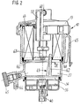
- Figure 2 one Longitudinal section through the liquid filter according to II-II in Figure 1 in a simplified representation
- Figure 3 a Top view of the lower part of a housing of the Liquid filter according to Figure 1
- Figure 4 is a view of End cap according to arrow IV in Figure 2 with an opposite figure 1 slightly modified holder of the molded sealing ring
- Figure 5 a longitudinal section according to IV-IV in Figure 4.
- FIG. 1 shows a longitudinal section through a Liquid filter 10 for cleaning diesel fuel with a two-part housing 11, which in All-plastic design is trained.
- the housing has a substantially cup-shaped lower part 12 and a lid-shaped upper part 13, both made of plastic consist. Bottom and top are through a quick screw closure 14 releasably connected to one another, for which a corresponding steep thread is provided and the upper part 13 engages over the lower part 12 on the outside.
- a Filter insert 16 with a radial flow from the inside to the outside arranged between one with an inlet connection 17th connected dirt side 18 and one with a clean side 19 connected drain port 21 is switched.
- FIG. 1 shows in connection with FIG. 2, goes the cup-shaped lower part 12 of a circular cylindrical, to the upper part 13 open section 22 via a annular shoulder 23 into a base section 24, whose outer diameter compared to section 22 is reduced.
- the shoulder thus forms one Interior 15 facing, annular Shoulder surface 25.
- In the below shoulder 23 lying base section 24 is between the bottom 26 thereof and the filter insert 16 a water storage space 27 formed with the clean side 19 in the filter insert 16th Has connection.
- the base section 24 has the Inlet port 17 arranged in a radial to Longitudinal axis 28 of the liquid filter 10 extending plane lies and which is also at an angle to the lateral surface of the Base section 24 runs, as is particularly the case in FIG. 3 clearly shows a top view of the lower part 12 represents.
- the inlet connection 17 is as Hose connection piece trained and leads the incoming Pressure medium directly into an inflow channel 29.
- Around this To accommodate inflow channel 29 in the base section 24 is in Area of the outer circumference of a sleeve-shaped thickening 31 molded, as shown in Figure 3 particularly clearly.
- the inflow channel 29 is like one blind hole-like recess is formed in the Shoulder 25 closed while he is in the floor 26 has lying opening 30.
- the axis of the inflow channel 29 also runs parallel to the longitudinal axis 28 of the Liquid filter 10.
- Housing 11 an electrical heating device 32 integrated, by being in a compact and space-saving design below of the base portion 24 is arranged.
- the housing 11 has for this purpose an essentially cup-shaped one Shell part 33, which with its free edge 34 tight and is firmly attached to the bottom 26 of the base portion 24.
- the Shell part 33 is also made of plastic and is expediently welded to the lower part 12.
- the Shell part 33 takes in its interior known per se Electric heating elements 35 on that to be cleaned Liquid flow can be washed around.
- heating elements 35 are thus in a boiler room 36, on the one hand the opening 31 of the inflow channel 29 with the inlet connection 17 has connection, while on the other hand via a Outflow channel 37 with the dirt side 18 on the filter insert 16 communicates.
- the outside of the shell part 33 is centric in the longitudinal axis 28 an electrical connector 40 for an electric heater 32 is arranged.
- FIG. 4 now shows a view of the lower end cap 46 according to arrow direction IV in Figure 2, from which the special Course of the molded seal 48 can be seen.
- FIG. 4 in connection with Figure 5 shows on the annular end cap 46 an annular Retaining plate 49 fastened by several welding spots 51, see above that the molded seal 48 with its L-shaped cross section can be hung.
- Molded seal 48 and holding plate 49 are designed so that the molded seal 48 substantially runs along the outer periphery of end cap 46, however in a region assigned to the first thickening 31 first indentation 52 and one in the area of the channel opening 39 the second indentation 53 associated with the second thickening 38 having.
- the axial height of the Form seal 48 is chosen so large that between the Channel opening 39 and the lower end cap 46 a sufficient high, radially extending flow area remains, through which the pressure medium to be cleaned to the outside in the annular space between the filter insert 16 and the section 22 of the housing 11 can flow.
- a groove 54 is also particularly clearly shown in FIG lower end cap 46 recognizable, in which the rib 42 for Reaching a function of the anti-rotation 43 introduced becomes.
- the axial length of this rib 42 is so great chosen that it protrudes into the filter insert 16. over there is a central opening 55 in the lower end cap 46 the clean side 19 directly with the water storage space 27 in connection.
- the drain port 21 is arranged as radially protruding hose connection piece is executed and that via an outlet channel 59 with annular Cross section with the clean side 19 is connected.
- the ring-shaped drain channel 59 surrounds a centrally located second drain channel 60, which is guided in an angular shape and leads to a second drain port 61.
- the second Drain connection 61 is coaxial with the first Drain connection 21 and is like this as Hose connection piece executed. Both connections 21, 61 are thus in a radial to the longitudinal axis 28 of the Liquid filter level.
- the second Drain channel 60 has one at the end of the pipe socket 56 in the Pipe-shaped extension 62 protruding from clean side 19, to which an overflow valve 63 is attached.
- This Overflow valve 63 is a replaceable valve cartridge executed and enables a spring-loaded ball valve an outflow of pressure medium from the clean side 19 to second drain connection 61 when the in the overflow valve 63rd set pressure is exceeded.
- a corrugated spring 64 is arranged, which the filter insert 16 presses on the shoulder surface 25 with the molded seal 48 and thus for a secure seal between dirt side and Clean side provides.
- a flange 65 is formed, like this can be seen particularly clearly from FIG.
- liquid filter 10 The operation of the liquid filter 10 is as follows explained, the basic function of such Filter is assumed to be known.
- the diesel fuel to be cleaned is the Liquid filter 10 fed to the inlet port 17 and flows via the inflow channel 29 directly into the Boiler room 36 of the electric heater 32. At The fuel is required there by the electrical Heating elements 35 heats and then flows from the heating room 36 further into the outflow channel 37. Via the channel opening 39 in the shoulder surface 25 and through that of the molded seal 48 delimited recess between the lower end cap 46 and the shoulder surface 25 he gets to the dirt side 18 of the filter insert 16. The diesel fuel flows through radially from the outside inwards the star-shaped Filter insert 16 and gets cleaned on the clean side 19.
- the housing 11 in Manufacture all-plastic design, essentially only a lower part 12 and an upper part 13 are necessary, when replacing a used filter insert 16 are easily separable.
- the liquid filter 10 is particularly compact, with the water storage space 27 and the heating device 32 in the narrowest space below of the filter insert 16 are arranged. It is also Overflow valve inside the liquid filter 10 integrated, so that the drain from the clean side to Injection pump on the one hand and on the other hand via the second Drain connection 61 to the tank, on the upper part 13 in the same Height are trained.
- the anti-rotation device 43 ensures simple and safe installation of the filter insert 16, the molded seal 48 with its second indentation 53 establishes the flow cross-section.
- the housing 11 is formed in the base portion 24 so that it can also be used for other applications without major changes is suitable, in particular can if necessary in the first Thickening 31 also a temperature-dependent switching Switch valve to be arranged, the first Indentation 52 forms a flow cross-section.
Landscapes
- Engineering & Computer Science (AREA)
- Chemical & Material Sciences (AREA)
- Combustion & Propulsion (AREA)
- Mechanical Engineering (AREA)
- General Engineering & Computer Science (AREA)
- Chemical Kinetics & Catalysis (AREA)
- Filtration Of Liquid (AREA)
Applications Claiming Priority (2)
| Application Number | Priority Date | Filing Date | Title |
|---|---|---|---|
| DE19811689A DE19811689A1 (de) | 1998-03-18 | 1998-03-18 | Flüssigkeitsfilter zum Reinigen von Kraftstoff |
| DE19811689 | 1998-03-18 |
Publications (3)
| Publication Number | Publication Date |
|---|---|
| EP0943796A2 true EP0943796A2 (fr) | 1999-09-22 |
| EP0943796A3 EP0943796A3 (fr) | 2000-05-17 |
| EP0943796B1 EP0943796B1 (fr) | 2003-10-08 |
Family
ID=7861275
Family Applications (1)
| Application Number | Title | Priority Date | Filing Date |
|---|---|---|---|
| EP98119364A Expired - Lifetime EP0943796B1 (fr) | 1998-03-18 | 1998-10-14 | Filtre à liquide pour purifier du carburant |
Country Status (2)
| Country | Link |
|---|---|
| EP (1) | EP0943796B1 (fr) |
| DE (2) | DE19811689A1 (fr) |
Cited By (10)
| Publication number | Priority date | Publication date | Assignee | Title |
|---|---|---|---|---|
| DE10124887A1 (de) * | 2001-05-22 | 2002-11-28 | Mahle Filtersysteme Gmbh | Wasserentleerungseinrichtung eines Kraftstofffilters |
| DE10124883A1 (de) * | 2001-05-22 | 2002-11-28 | Mahle Filtersysteme Gmbh | Kraftstofffilter eines Kraftfahrzeug-Verbrennungsmotors |
| WO2003076793A1 (fr) * | 2002-03-08 | 2003-09-18 | Ufi Filters S.P.A. | Filtre a carburant equipe d'un generateur de chaleur autochauffant |
| WO2005009588A1 (fr) * | 2003-07-22 | 2005-02-03 | Robert Bosch Gmbh | Filtre a carburant |
| WO2005031148A1 (fr) * | 2003-09-29 | 2005-04-07 | Ufi Filters S.P.A. | Filtre a gazole |
| US6881328B2 (en) | 2001-05-22 | 2005-04-19 | Mahle Filtersysteme Gmbh | Method for evacuating water that has been separated in a fuel filter and a device for carrying out said method |
| WO2008059423A1 (fr) * | 2006-11-13 | 2008-05-22 | Mahle Tennex Industries, Inc. | Système de traitement d'eau séparée pour moteur à carburant diesel |
| CN102345541A (zh) * | 2011-11-02 | 2012-02-08 | 中国重汽集团济南动力有限公司 | 一种柴油滤清器加热装置 |
| EP2514958A1 (fr) * | 2011-04-19 | 2012-10-24 | Mann + Hummel Gmbh | Filtre de carburant pour un moteur à combustion interne |
| RU2478823C2 (ru) * | 2009-09-08 | 2013-04-10 | Федеральное государственное унитарное предприятие "Центральный ордена Трудового Красного Знамени научно-исследовательский автомобильный и автомоторный институт "НАМИ" | Фильтр грубой очистки биотоплива |
Families Citing this family (5)
| Publication number | Priority date | Publication date | Assignee | Title |
|---|---|---|---|---|
| DE19950888A1 (de) * | 1999-10-22 | 2001-04-26 | Bayerische Motoren Werke Ag | Ölfiltervorrichtung für Brennkraftmaschinen |
| DE10023649B4 (de) * | 2000-05-13 | 2012-11-22 | Mahle Filtersysteme Gmbh | Mit einer Heizeinrichtung versehenes Kraftstoffilter für Kraftfahrzeuge |
| JP4376716B2 (ja) * | 2004-07-20 | 2009-12-02 | トヨタ自動車株式会社 | フューエルフィルタ |
| KR101189226B1 (ko) * | 2006-02-03 | 2012-10-09 | 현대자동차주식회사 | 연료시스템의 수분 분리장치 |
| DE102010038338A1 (de) * | 2010-03-23 | 2011-09-29 | Robert Bosch Gmbh | Filtereinrichtung mit mindestens zwei Anschlussstutzen |
Citations (2)
| Publication number | Priority date | Publication date | Assignee | Title |
|---|---|---|---|---|
| US5433241A (en) | 1994-04-13 | 1995-07-18 | Siemens Automotive L.P. | Fuel pressure regulator/fuel filter module |
| EP0702144A2 (fr) | 1994-09-13 | 1996-03-20 | Robert Bosch Gmbh | Elément de filtrage interchangeable et boîtier filtrant pour le montage de l'élément de filtrage interchangeable |
Family Cites Families (3)
| Publication number | Priority date | Publication date | Assignee | Title |
|---|---|---|---|---|
| US4619764A (en) * | 1984-06-19 | 1986-10-28 | Parker-Hannifin Corporation | Repelling-action filter unit and assembly |
| US4666597A (en) * | 1985-09-10 | 1987-05-19 | Hurner Erwin E | Fuel treatment apparatus |
| JPS62277115A (ja) * | 1986-02-25 | 1987-12-02 | Nippon Denso Co Ltd | 燃料加熱装置 |
-
1998
- 1998-03-18 DE DE19811689A patent/DE19811689A1/de not_active Withdrawn
- 1998-10-14 EP EP98119364A patent/EP0943796B1/fr not_active Expired - Lifetime
- 1998-10-14 DE DE59809863T patent/DE59809863D1/de not_active Expired - Fee Related
Patent Citations (2)
| Publication number | Priority date | Publication date | Assignee | Title |
|---|---|---|---|---|
| US5433241A (en) | 1994-04-13 | 1995-07-18 | Siemens Automotive L.P. | Fuel pressure regulator/fuel filter module |
| EP0702144A2 (fr) | 1994-09-13 | 1996-03-20 | Robert Bosch Gmbh | Elément de filtrage interchangeable et boîtier filtrant pour le montage de l'élément de filtrage interchangeable |
Cited By (13)
| Publication number | Priority date | Publication date | Assignee | Title |
|---|---|---|---|---|
| DE10124883A1 (de) * | 2001-05-22 | 2002-11-28 | Mahle Filtersysteme Gmbh | Kraftstofffilter eines Kraftfahrzeug-Verbrennungsmotors |
| US6881328B2 (en) | 2001-05-22 | 2005-04-19 | Mahle Filtersysteme Gmbh | Method for evacuating water that has been separated in a fuel filter and a device for carrying out said method |
| DE10124887A1 (de) * | 2001-05-22 | 2002-11-28 | Mahle Filtersysteme Gmbh | Wasserentleerungseinrichtung eines Kraftstofffilters |
| WO2003076793A1 (fr) * | 2002-03-08 | 2003-09-18 | Ufi Filters S.P.A. | Filtre a carburant equipe d'un generateur de chaleur autochauffant |
| US8017009B2 (en) | 2003-07-22 | 2011-09-13 | Robert Bosch Gmbh | Fuel filter |
| WO2005009588A1 (fr) * | 2003-07-22 | 2005-02-03 | Robert Bosch Gmbh | Filtre a carburant |
| WO2005031148A1 (fr) * | 2003-09-29 | 2005-04-07 | Ufi Filters S.P.A. | Filtre a gazole |
| WO2008059423A1 (fr) * | 2006-11-13 | 2008-05-22 | Mahle Tennex Industries, Inc. | Système de traitement d'eau séparée pour moteur à carburant diesel |
| RU2478823C2 (ru) * | 2009-09-08 | 2013-04-10 | Федеральное государственное унитарное предприятие "Центральный ордена Трудового Красного Знамени научно-исследовательский автомобильный и автомоторный институт "НАМИ" | Фильтр грубой очистки биотоплива |
| EP2514958A1 (fr) * | 2011-04-19 | 2012-10-24 | Mann + Hummel Gmbh | Filtre de carburant pour un moteur à combustion interne |
| KR20120123212A (ko) * | 2011-04-19 | 2012-11-08 | 만 운트 훔멜 게엠베하 | 내연 기관용 연료 필터 |
| CN102345541A (zh) * | 2011-11-02 | 2012-02-08 | 中国重汽集团济南动力有限公司 | 一种柴油滤清器加热装置 |
| CN102345541B (zh) * | 2011-11-02 | 2012-11-28 | 中国重汽集团济南动力有限公司 | 一种柴油滤清器加热装置 |
Also Published As
| Publication number | Publication date |
|---|---|
| DE19811689A1 (de) | 1999-09-23 |
| EP0943796B1 (fr) | 2003-10-08 |
| EP0943796A3 (fr) | 2000-05-17 |
| DE59809863D1 (de) | 2003-11-13 |
Similar Documents
| Publication | Publication Date | Title |
|---|---|---|
| EP0314915B1 (fr) | Filtre permettant la purification des huiles de graissage | |
| EP1307274B1 (fr) | Filtre pour liquide, en particulier pour huile de lubrification d'un moteur a combustion | |
| DE69413151T2 (de) | Ölfilterpatrone | |
| EP0943796B1 (fr) | Filtre à liquide pour purifier du carburant | |
| DE19502020C2 (de) | Flüssigkeitsfilter | |
| DE60204885T2 (de) | Anschraubbarer filter und entsprechender filterkopf | |
| DE1152285B (de) | Ventilanordnung fuer Schmieroelfilter von Brennkraftmaschinen | |
| DE3538589A1 (de) | Oelfilter zum reinigen von schmieroel | |
| DE10106950A1 (de) | Filterelement für Kraftstoffe | |
| DE19538883A1 (de) | Filter für Flüssigkeiten, insbesondere Dieselkraftstoff | |
| WO2008014846A1 (fr) | Dispositif de filtration | |
| EP2192966A1 (fr) | Dispositif de filtration et élément filtrant | |
| EP0848978B1 (fr) | Tube support destiné à recevoir un élément filtrant annulaire | |
| EP0385113A2 (fr) | Filtre de liquide | |
| WO2018086724A1 (fr) | Dispositif de filtration | |
| DE4330839C2 (de) | Filter für die Reinigung von Flüssigkeiten | |
| EP4188574B1 (fr) | Réservoir d'eau pourvu d'une cartouche filtre | |
| DE102011120646B4 (de) | Flüssigkeitsfilter und Filterelement mit Ablaufschwert eines Flüssigkeitsfilters | |
| EP0899452B1 (fr) | Filtre pour liquides pour filtrer du carburant | |
| EP4312681B1 (fr) | Filtre comprenant un dispositif de centrage | |
| EP4208277B1 (fr) | Réservoir d'eau doté d'une cartouche filtrante | |
| DE4231999A1 (de) | Filter zum Reinigen von Kraftstoff | |
| DE19508650A1 (de) | Filteranordnung | |
| EP3160614B1 (fr) | Système de filtration et filtre pour liquides | |
| EP1316347B1 (fr) | Filtre à liquide pour purifier du carburant |
Legal Events
| Date | Code | Title | Description |
|---|---|---|---|
| PUAI | Public reference made under article 153(3) epc to a published international application that has entered the european phase |
Free format text: ORIGINAL CODE: 0009012 |
|
| AK | Designated contracting states |
Kind code of ref document: A2 Designated state(s): DE ES FR GB IT |
|
| AX | Request for extension of the european patent |
Free format text: AL;LT;LV;MK;RO;SI |
|
| PUAL | Search report despatched |
Free format text: ORIGINAL CODE: 0009013 |
|
| AK | Designated contracting states |
Kind code of ref document: A3 Designated state(s): AT BE CH CY DE DK ES FI FR GB GR IE IT LI LU MC NL PT SE |
|
| AX | Request for extension of the european patent |
Free format text: AL;LT;LV;MK;RO;SI |
|
| 17P | Request for examination filed |
Effective date: 20001117 |
|
| AKX | Designation fees paid |
Free format text: DE ES FR GB IT |
|
| GRAH | Despatch of communication of intention to grant a patent |
Free format text: ORIGINAL CODE: EPIDOS IGRA |
|
| GRAS | Grant fee paid |
Free format text: ORIGINAL CODE: EPIDOSNIGR3 |
|
| GRAA | (expected) grant |
Free format text: ORIGINAL CODE: 0009210 |
|
| AK | Designated contracting states |
Kind code of ref document: B1 Designated state(s): DE ES FR GB IT |
|
| PG25 | Lapsed in a contracting state [announced via postgrant information from national office to epo] |
Ref country code: GB Free format text: LAPSE BECAUSE OF FAILURE TO SUBMIT A TRANSLATION OF THE DESCRIPTION OR TO PAY THE FEE WITHIN THE PRESCRIBED TIME-LIMIT Effective date: 20031008 |
|
| REG | Reference to a national code |
Ref country code: GB Ref legal event code: FG4D Free format text: NOT ENGLISH |
|
| REF | Corresponds to: |
Ref document number: 59809863 Country of ref document: DE Date of ref document: 20031113 Kind code of ref document: P |
|
| PG25 | Lapsed in a contracting state [announced via postgrant information from national office to epo] |
Ref country code: ES Free format text: LAPSE BECAUSE OF FAILURE TO SUBMIT A TRANSLATION OF THE DESCRIPTION OR TO PAY THE FEE WITHIN THE PRESCRIBED TIME-LIMIT Effective date: 20040119 |
|
| GBV | Gb: ep patent (uk) treated as always having been void in accordance with gb section 77(7)/1977 [no translation filed] |
Effective date: 20031008 |
|
| ET | Fr: translation filed | ||
| PLBE | No opposition filed within time limit |
Free format text: ORIGINAL CODE: 0009261 |
|
| STAA | Information on the status of an ep patent application or granted ep patent |
Free format text: STATUS: NO OPPOSITION FILED WITHIN TIME LIMIT |
|
| 26N | No opposition filed |
Effective date: 20040709 |
|
| PGFP | Annual fee paid to national office [announced via postgrant information from national office to epo] |
Ref country code: DE Payment date: 20051220 Year of fee payment: 8 |
|
| PGFP | Annual fee paid to national office [announced via postgrant information from national office to epo] |
Ref country code: IT Payment date: 20061031 Year of fee payment: 9 |
|
| PG25 | Lapsed in a contracting state [announced via postgrant information from national office to epo] |
Ref country code: DE Free format text: LAPSE BECAUSE OF NON-PAYMENT OF DUE FEES Effective date: 20070501 |
|
| REG | Reference to a national code |
Ref country code: FR Ref legal event code: ST Effective date: 20080630 |
|
| PGFP | Annual fee paid to national office [announced via postgrant information from national office to epo] |
Ref country code: FR Payment date: 20061020 Year of fee payment: 9 |
|
| PG25 | Lapsed in a contracting state [announced via postgrant information from national office to epo] |
Ref country code: FR Free format text: LAPSE BECAUSE OF NON-PAYMENT OF DUE FEES Effective date: 20071031 |
|
| PG25 | Lapsed in a contracting state [announced via postgrant information from national office to epo] |
Ref country code: IT Free format text: LAPSE BECAUSE OF NON-PAYMENT OF DUE FEES Effective date: 20071014 |