EP0943820A2 - Ensemble-raccord et moyens de raccord appropriés - Google Patents
Ensemble-raccord et moyens de raccord appropriés Download PDFInfo
- Publication number
- EP0943820A2 EP0943820A2 EP99104458A EP99104458A EP0943820A2 EP 0943820 A2 EP0943820 A2 EP 0943820A2 EP 99104458 A EP99104458 A EP 99104458A EP 99104458 A EP99104458 A EP 99104458A EP 0943820 A2 EP0943820 A2 EP 0943820A2
- Authority
- EP
- European Patent Office
- Prior art keywords
- pin
- component
- fitting
- cork
- components
- Prior art date
- Legal status (The legal status is an assumption and is not a legal conclusion. Google has not performed a legal analysis and makes no representation as to the accuracy of the status listed.)
- Withdrawn
Links
- 239000007799 cork Substances 0.000 claims abstract description 98
- 239000000463 material Substances 0.000 claims abstract description 16
- 239000004033 plastic Substances 0.000 claims abstract description 6
- 229920003023 plastic Polymers 0.000 claims abstract description 6
- 238000004064 recycling Methods 0.000 claims abstract description 3
- 239000011324 bead Substances 0.000 claims description 4
- 238000010276 construction Methods 0.000 claims description 4
- 230000000149 penetrating effect Effects 0.000 claims description 4
- 239000003795 chemical substances by application Substances 0.000 claims description 3
- 230000002093 peripheral effect Effects 0.000 claims description 3
- 239000002131 composite material Substances 0.000 claims description 2
- 239000007787 solid Substances 0.000 claims description 2
- 239000011343 solid material Substances 0.000 claims description 2
- 125000006850 spacer group Chemical group 0.000 claims description 2
- XAGFODPZIPBFFR-UHFFFAOYSA-N aluminium Chemical compound [Al] XAGFODPZIPBFFR-UHFFFAOYSA-N 0.000 claims 1
- 229910052782 aluminium Inorganic materials 0.000 claims 1
- 238000003801 milling Methods 0.000 claims 1
- 239000000123 paper Substances 0.000 claims 1
- 230000007704 transition Effects 0.000 claims 1
- 239000002023 wood Substances 0.000 claims 1
- 150000001875 compounds Chemical class 0.000 abstract 1
- 230000001419 dependent effect Effects 0.000 abstract 1
- 238000003892 spreading Methods 0.000 description 7
- 230000015572 biosynthetic process Effects 0.000 description 3
- 238000013016 damping Methods 0.000 description 2
- 230000000694 effects Effects 0.000 description 2
- 210000003128 head Anatomy 0.000 description 2
- 238000003825 pressing Methods 0.000 description 2
- OKTJSMMVPCPJKN-UHFFFAOYSA-N Carbon Chemical compound [C] OKTJSMMVPCPJKN-UHFFFAOYSA-N 0.000 description 1
- 241001295925 Gegenes Species 0.000 description 1
- 241000701193 Mutellina purpurea Species 0.000 description 1
- 230000006978 adaptation Effects 0.000 description 1
- 230000005540 biological transmission Effects 0.000 description 1
- 238000000576 coating method Methods 0.000 description 1
- 230000006835 compression Effects 0.000 description 1
- 238000007906 compression Methods 0.000 description 1
- 239000010791 domestic waste Substances 0.000 description 1
- 238000005516 engineering process Methods 0.000 description 1
- 230000003203 everyday effect Effects 0.000 description 1
- 210000001061 forehead Anatomy 0.000 description 1
- 239000011121 hardwood Substances 0.000 description 1
- 238000009776 industrial production Methods 0.000 description 1
- 238000009413 insulation Methods 0.000 description 1
- 230000003993 interaction Effects 0.000 description 1
- 238000004519 manufacturing process Methods 0.000 description 1
- 239000002184 metal Substances 0.000 description 1
- 229910052751 metal Inorganic materials 0.000 description 1
- 150000002739 metals Chemical class 0.000 description 1
- 239000002994 raw material Substances 0.000 description 1
- 230000000630 rising effect Effects 0.000 description 1
- 238000000926 separation method Methods 0.000 description 1
- 238000004904 shortening Methods 0.000 description 1
Images




Classifications
-
- F—MECHANICAL ENGINEERING; LIGHTING; HEATING; WEAPONS; BLASTING
- F16—ENGINEERING ELEMENTS AND UNITS; GENERAL MEASURES FOR PRODUCING AND MAINTAINING EFFECTIVE FUNCTIONING OF MACHINES OR INSTALLATIONS; THERMAL INSULATION IN GENERAL
- F16B—DEVICES FOR FASTENING OR SECURING CONSTRUCTIONAL ELEMENTS OR MACHINE PARTS TOGETHER, e.g. NAILS, BOLTS, CIRCLIPS, CLAMPS, CLIPS OR WEDGES; JOINTS OR JOINTING
- F16B12/00—Jointing of furniture or the like, e.g. hidden from exterior
- F16B12/10—Jointing of furniture or the like, e.g. hidden from exterior using pegs, bolts, tenons, clamps, clips, or the like
- F16B12/12—Jointing of furniture or the like, e.g. hidden from exterior using pegs, bolts, tenons, clamps, clips, or the like for non-metal furniture parts, e.g. made of wood, of plastics
- F16B12/24—Jointing of furniture or the like, e.g. hidden from exterior using pegs, bolts, tenons, clamps, clips, or the like for non-metal furniture parts, e.g. made of wood, of plastics using separate pins, dowels, or the like
-
- F—MECHANICAL ENGINEERING; LIGHTING; HEATING; WEAPONS; BLASTING
- F16—ENGINEERING ELEMENTS AND UNITS; GENERAL MEASURES FOR PRODUCING AND MAINTAINING EFFECTIVE FUNCTIONING OF MACHINES OR INSTALLATIONS; THERMAL INSULATION IN GENERAL
- F16B—DEVICES FOR FASTENING OR SECURING CONSTRUCTIONAL ELEMENTS OR MACHINE PARTS TOGETHER, e.g. NAILS, BOLTS, CIRCLIPS, CLAMPS, CLIPS OR WEDGES; JOINTS OR JOINTING
- F16B12/00—Jointing of furniture or the like, e.g. hidden from exterior
- F16B12/10—Jointing of furniture or the like, e.g. hidden from exterior using pegs, bolts, tenons, clamps, clips, or the like
- F16B12/12—Jointing of furniture or the like, e.g. hidden from exterior using pegs, bolts, tenons, clamps, clips, or the like for non-metal furniture parts, e.g. made of wood, of plastics
Definitions
- the invention relates to a fitting system for connecting of components, for the construction and furnishing of furniture, Utensils, interiors and the like, also on hardware for use with this hardware system.
- a multi-functional Fitting means in the form of a pin with a circular Cross-section, in particular a bottle cork, in a Recess of a first component is received, where the pin cross-section of the recess can adapt, and with a section projecting above the first component into a recess aligned with the recess of the first component engages a second component.
- the fitting system according to the invention is based on extremely simple ones Hardware that is new or used Trade bottle corks from cork material or plastic can be made from paper, recycled material or from Composites can be made.
- the manageability is good and industrial production is very easy to do and especially when using hardware made of cork material, paper or other rotting materials Easy disposal of materials is guaranteed.
- the recesses to be provided in the components for the receptacle of the respective fitting means can basically be any be designed. Has proven to be particularly advantageous, however the formation of these recesses proved to be bores, which can be introduced into the components in a simple manner.
- each pin can be on the other component protrude from the opposite side of a component and on the protruding pin sections can be secured be like snap rings, rubber rings or on the protruding ones Pin sections screwed nuts.
- the pin cross section adapts to the nut on the one hand and on the other hand the recess into which the pin is inserted is.
- connection for example, plate-shaped components that immediately abut in contact areas or spaced apart are fixed from each other, for example by one on one penetrating the through holes as fittings Spigot absorbed spacer.
- distance means can be sleeves or the like.
- the pin forming the fitting such as a bottle cork
- this component over the other
- the pivotable articulation of one succeeds Double door to a furniture body.
- An improved pivotable articulation of a component on another component is achieved if according to a training the invention in the bore of one of the components, a bearing element, about a ball or roller bearing is added, and this on the engaging portion of the Fitting means forming pin is added.
- Another development of the invention provides that in at least one of the components that the pin as a fitting receiving bore or the bore into which the other Component protruding pin section engages as a blind hole is trained.
- This variant of the invention task comes in particular then meaning when a component with an end face another component is to be connected.
- the Thickness of the component to be connected at the end is definitely smaller be than the diameter of the fitting in which Fall the hole symmetrical to the thickness of the hardware is to be inserted at the end of the component and that Fitting means on both sides in the area of the blind hole protrudes over the flat sides of the component.
- Another useful development of the invention is by connecting a tubular component, such as one Clothes rail, marked with another component by one in a bore of the latter component with a press fit picked pin as a fitting with a section protrudes from the named component and in front the tubular component engages.
- a tubular component such as one Clothes rail
- the fitting means according to the invention is not only a Means of connecting components can be used, but also as a means of protection. This is a further development of the invention by using the pin as a means of securing one Plug connection of a first and second component marked, by placing the pin in the area of the connector arranged bore of a component is received and engages at least in sections in bore areas that extend in the second component.
- the one that forms the fitting means Pin also be provided with a central longitudinal recess and a stiffening pin can be received in the longitudinal recess be, which also protrude from the spigot and serve for example to attach any objects can.
- the pin forming the fitting means can also be used as Spreading element be formed so that the pressing in Pin, for example, with a press fit into a hole effective clamping of the pin with the walls of one Pin-receiving bore succeeds.
- the expansion means can be a through the longitudinal recess extending in the cone, with one head on one Supporting tensioning screw and around one by means of this clamping screw from the other end of the cone act out of a retractable clamping cone, the one depending on the drawing into the longitudinal recess radial expansion of the pin causes.
- a conical clamping pin can also serve as an expansion means, that from a cone front into which the Pin extending longitudinal recess is driven.
- Another design of the pin forming the fitting means as a spreading element provides that as a spreading means Double wedge with two expansion bodies, which is used in the longitudinal direction wedge surfaces that rise in opposite directions lie against each other and from opposite ends of the pin in its Longitudinal recess can be driven.
- the expanding means comprises one in the longitudinal recess of the Spigot received expansion sleeve, the middle part with longitudinal slots and on one side with the longitudinal slots a nut arranged axially fixed in the expansion sleeve is also a extending through the expansion sleeve Clamping screw in the nut of the expansion sleeve is screwed in and with a screw head on the of supports the end of the cone facing away from the mother.
- the one that forms the fitting means Pin also provided with an eccentric and rotatable in one adapted recess of a component can be accommodated in such a way that depending on the rotational position of the pin Eccentric more or less over a frontal boundary of the named component protrudes and with an adjacent one Component is clamped.
- Eccentric hardware Presentation walls in exhibition stand construction be tense.
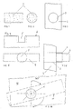
- FIGS. 1 and 2 it is a conventional bottle cork 1 with circular cylindrical cross-section and one about twice Diameter corresponding length.
- Such corks 1 are in can be used in various ways as a fitting means, such as that a predetermined length of the cork 1 with a press fit into a bore 3 extending in a component 2 is pressed and the section protruding from the component of the cork 1 in a extending in another component Recess engages.
- FIG. 6 shows the connection of the strip-shaped component 4 with the component 2 according to FIG. 3 using the cork 1 shown as a fitting.
- the cork 1 is in the in the latter component extending bore 3 with a press fit recorded and engages in the trained as a blind hole Recess 5 of component 4. Because the diameter of the recess 5 exceeds the thickness of the strip-shaped component 4, is the cork 1, as shown in FIG. 6, in the area of blind hole-like recess 5 on both sides of the strip-shaped Component 5 before.
- connection technology also succeeds at the front end without any problems Connection of a strip-shaped component 6 to another Component 7 by means of a cork 1 as a connecting fitting means. Analogously to FIGS. 4 to 6, this shows the 7 and 8.
- corks 1 as a fitting means articulated connections between components 10, 11 can be realized, which is indicated in Fig. 10.
- the as a fitting serving cork 1 is part of its length in a bore adapted to the cross section of the cork in the first component 10 added and engages with limited play into one from one end into the other component 11 extending blind hole.
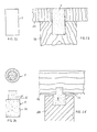
- Bottle corks 1 as fittings are also for example to fix a tubular clothes rail on a side cheek a cabinet can be used.
- 11 shows the recording one protruding on one side over a side cheek 11 Cork 1 with a press fit in a side wall penetrating Hole 3 and the protruding portion of the cork 1 engages in a tubular clothes rail 12 at the end. This is a precise, but easy to dismantle Definition of such a clothes rail 12 guaranteed.
- a clothes rail on one of a side cheek 11 laterally projecting section of a hole serves a shelf 13, which is illustrated in Fig. 12 is.
- Such shelves 13 are expediently provided on the underside arranged milled hole-like cutouts 14 into which the protruding portion of the cork 1 engages when the shelf 13 rests and thereby this in secures its position.
- Fig. 14 shows the connection of two components 15, 16, wherein the component 15 with two end faces spaced apart from one another protruding pin 17 in accordance with the pin arrangement spaced-apart recesses 18 of the other component 16 engages.
- a central pin 19 of the component 16 is with a its thickness exceeding bore 3 provided on both sides extends beyond the middle plug 19 and in the type of circular sections also the two plug pins 17th of the other component 15 is detected.
- a pressed into the bore 3 Cork pin 1 thus conveys a form-fitting, however detachable connection of the plug pins of both components 15, 16 and thus the components themselves.
- Fig. 15 is using cork pin 1 as a connecting fitting means building an otherwise uninteresting Shelf 20 illustrates.
- the cork 1 illustrated in FIG. 16 is in the area of it equipped at both ends with snap rings 20, which under one certain bias on the cork 1 are added.
- snap rings 20 can also, as shown in FIG. 17 shows, on the cork 1 in the area of its two ends rubber rings 21 be included.
- Such securing means in the form of snap rings 20 or Rubber rings 21 are important, for example, when on which there is between the spring rings 20 and rubber rings 21 extending area of the cork 1 two components stored are, by means of the snap rings 20 or rubber rings 21 in their intended positions are kept.
- the cork can be used from one component to another component 1 also with a bearing element, for example a needle bearing 22 or a roller bearing 23, as shown in FIGS. 18 and 19 show.
- a bearing element for example a needle bearing 22 or a roller bearing 23, as shown in FIGS. 18 and 19 show.
- the outer rings such bearing elements 22, 23 in the bore of a Component included and in a hole in the other component engaging cork 1 is rotationally fixed, for example with a press fit, in the inner ring of a bearing element 22, 23, whereby a low-friction rotatability of the two hinged together Components is guaranteed.
- FIGS. 16 and 17 are axial securing devices, analogous to FIGS. 16 and 17 of components accommodated on the cork 1 realizes that on the frontal sections of the cork 1 nuts 24 are screwed on.
- cork pin 1 illustrates one with a central longitudinal recess 25 provided cork pin 1 and one in the mentioned Longitudinal recess drivable core 26 which, for example, consists of Hardwood can exist and the transverse rigidity of the cork cone sustainably improved.
- Kerns 26 can also over at least one side the cork pin 1 protruding cores are used, the also at their projecting end radially projecting head parts can have.
- cork cones designed in this way Cores protruding from one end face are easier to achieve Way of building a wardrobe, for example.
- FIG. 22 shows a waisted cork pin 1, that shown, for example, in FIG. 23 Way for connecting components 27, 28 is suitable, which in abut a contact surface.
- the tailored training of the cork pin 1 causes after being pressed into the Locating holes of the two components so that they are under tension be kept in contact in their contact area.
- the cork pin 1 illustrated in FIG. 24 has two Pin sections 30, 31 of different diameters, the separated from one another by an unmoving annular shoulder 32 are.
- Such cork pins are suitable, for example, for spacing Connection of two components 33, 34, like this Figure 25 illustrates.
- the larger diameter having pin portion 30 in a blind hole of the Component 34 added and is axially by a desired amount over the end face of this component.
- the smaller diameter having pin portion 31 engages in a blind hole of the other component 33 and this blind hole surrounding edges of the first component 34 pointing Area from which the blind hole into the second Component is inserted, lies on the between the two Pin sections 30, 31 circumferential shoulder 32 of the cork pin on.
- Such a component connection is important when the transmission of structure-borne noise from a component the other component should be minimized.
- the same effect can also be used when using cylindrical cork cones can be achieved by a damping element on the cork, For example, a rubber washer is added by means of the facing surfaces of the interconnected Components are separated.
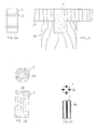
- the cork pin 1 illustrated in FIG. 26 has two from each other and from the respective ends of the cork pin spaced circumferential annular beads 35 equipped.
- Means cork cones formed in this way create a positive connection of the components 36, 37 by the blind hole in the component 36 and the through hole in component 37 each with one suitably arranged and dimensioned ring groove are in the radially from when pressing the cork pin 1 snap this projecting annular beads 35.
- the cork pin 1 illustrated in FIG. 28 has four longitudinal grooves evenly distributed over its circumference 38 equipped in which longitudinal slats 40 can be accommodated as shown in Fig. 29.
- Such slats can used to distance and improve about it the transverse rigidity and / or shear strength of the cork pin 1.
- the base body made of solid and / or rigid material to form and to provide compressible slats in reverse the choice of material for the example described.
- the cork pegs used as fittings can also be designed as spreading elements. Possible embodiments are illustrated in Figures 30-33.
- the used Cork pins 1 have these expansion elements, such as the 21, a central and continuous Longitudinal recess 25.
- two serve in opposite directions rising wedge surfaces provided expansion bodies 45, 46 as Spreading agent from opposite ends of the cork pin 1 can be driven into its longitudinal recess 25 with the consequence that when driving the expansion body 45, 46 in the Longitudinal recess 25 in view of the opposing wedge surfaces a radial expansion of the cork cone over its entire length Length.
- the cork pin 1 serves as a spreading means one from an end of the cork pin 1 in the Longitudinal recess 25 drivable conical clamping pin 48 experiences this embodiment as well as in the embodiment 30, the cork pin 1 a radial expansion especially in the areas adjacent to the driving side.
- Expansion sleeve 50 comprise the expansion means of this embodiment a clamping screw 42, which can be seen in FIG. 30 kind of with a screw head 43 on that of the mother 52 of the expansion sleeve 50 removed end of the cork pin 1 is supported and screwed into the nut 52.
- Cork pin 1 is the bracing of two components 54, 55 against each other by means of one equipped with a clamping eccentric 56
- Cork pin 1 illustrates.
- the clamping eccentric 56 is approximately in the middle of the longitudinal extension of the cork pin 1 arranged and the latter in a transverse bore on the edge of Component 54 rotatably added.
- In the cross hole is one grooved groove corresponding to the dimensions of the clamping eccentric 56, in such a way that the groove the relevant end face of component 54 breaks through.
- a forehead of the pin 1 is inserted into a cross recess 57, which are twisted using a Phillips screwdriver of the cork pin about its longitudinal axis in the receiving bore of component 54 allowed.
- FIG. 34 shows that a component 54 is touching Component 55 can be clamped to component 54 in a simple manner is in which the equipped with the clamping eccentric 56 Cork spigot in the bore of component 54 that receives it accordingly rotated about its longitudinal axis and thereby the Clamping eccentric 56 brought into interaction with the component 55 becomes.
Landscapes
- Engineering & Computer Science (AREA)
- General Engineering & Computer Science (AREA)
- Mechanical Engineering (AREA)
- Furniture Connections (AREA)
- Connection Of Plates (AREA)
Applications Claiming Priority (6)
| Application Number | Priority Date | Filing Date | Title |
|---|---|---|---|
| DE29803857U | 1998-03-05 | ||
| DE29803857U DE29803857U1 (de) | 1998-03-05 | 1998-03-05 | Mehrfachfunktionales Korkenbeschlagsmittel |
| DE29814186U DE29814186U1 (de) | 1998-03-05 | 1998-08-07 | Mehrfachfunktionales Korkenbeschlagsmittel |
| DE29814186U | 1998-08-07 | ||
| DE19909396A DE19909396A1 (de) | 1998-03-05 | 1999-03-04 | Beschlagsystem und Beschlagmittel hierfür |
| DE19909396 | 1999-03-04 |
Publications (2)
| Publication Number | Publication Date |
|---|---|
| EP0943820A2 true EP0943820A2 (fr) | 1999-09-22 |
| EP0943820A3 EP0943820A3 (fr) | 2002-07-31 |
Family
ID=27219010
Family Applications (1)
| Application Number | Title | Priority Date | Filing Date |
|---|---|---|---|
| EP99104458A Withdrawn EP0943820A3 (fr) | 1998-03-05 | 1999-03-04 | Ensemble-raccord et moyens de raccord appropriés |
Country Status (1)
| Country | Link |
|---|---|
| EP (1) | EP0943820A3 (fr) |
Family Cites Families (1)
| Publication number | Priority date | Publication date | Assignee | Title |
|---|---|---|---|---|
| EP0340885A3 (fr) * | 1988-02-05 | 1992-01-02 | Kohichi Yasumuro | Structure de plaque de dessus à contours différents et extensions pour meubles, structure de mobilier variable en hauteur utilisant la structure de la plaque du dessus |
-
1999
- 1999-03-04 EP EP99104458A patent/EP0943820A3/fr not_active Withdrawn
Non-Patent Citations (1)
| Title |
|---|
| None |
Also Published As
| Publication number | Publication date |
|---|---|
| EP0943820A3 (fr) | 2002-07-31 |
Similar Documents
| Publication | Publication Date | Title |
|---|---|---|
| DE3923996C2 (fr) | ||
| DE2819744C2 (de) | Scharnier, insbesondere Brillenscharnier | |
| DE102020127075B4 (de) | Drehherz und Spannvorrichtung mit diesem Drehherz | |
| DD284623A5 (de) | Spannvorrichtung | |
| WO1994007040A1 (fr) | Dispositif pour relier au moins deux elements | |
| CH656335A5 (de) | Bohrwerkzeug. | |
| EP0490086B1 (fr) | Raccord à vis pour assembler au moins deux pièces de manière détachable, notamment des barres profilées pourvues de rainures longitudinales | |
| DE2544498B2 (de) | Gewindering | |
| EP0787907B1 (fr) | Support de construction pour un système de mobilier, en particulier pour un système de construction de placards | |
| DE68926336T2 (de) | Bolzeneinrichtung | |
| DE2609186A1 (de) | Sicherheitsmutter | |
| DE9200911U1 (de) | Befestigungsvorrichtung | |
| DE60004802T2 (de) | Verbindung zur Montage von Regalen oder Trägerelementen auf Gestellen | |
| EP0943820A2 (fr) | Ensemble-raccord et moyens de raccord appropriés | |
| DE10138220C1 (de) | Verbindung einer geschlitzten Hohlwelle mit einem in sie eingreifenden Gegenstück | |
| DE19909396A1 (de) | Beschlagsystem und Beschlagmittel hierfür | |
| DE102010010209B4 (de) | Matrizenscheibe | |
| DE2457290C3 (de) | Werkzeugheft | |
| DE20002201U1 (de) | Vorrichtung zum Verbinden einer Tischplatte mit einem Tischfuß | |
| DE19920544A1 (de) | Gelenk für ein Werkzeug | |
| EP0933854A1 (fr) | Traversée murale pour montage dans un trou traversant un mur | |
| EP0604696B1 (fr) | Dispositif de fixation | |
| EP0598289A1 (fr) | Boulon de centrage pour la fixation, le centrage et/ou le positionnement des éléments avec des trous de centrage | |
| DE2221594A1 (de) | Verbindungselement fuer Konstruktionsteile | |
| DE3340964A1 (de) | Aufbaumoebel, insbesondere regal |
Legal Events
| Date | Code | Title | Description |
|---|---|---|---|
| PUAI | Public reference made under article 153(3) epc to a published international application that has entered the european phase |
Free format text: ORIGINAL CODE: 0009012 |
|
| AK | Designated contracting states |
Kind code of ref document: A2 Designated state(s): AT BE CH CY DE DK ES FI FR GB GR IE IT LI LU MC NL PT SE |
|
| AX | Request for extension of the european patent |
Free format text: AL;LT;LV;MK;RO;SI |
|
| PUAL | Search report despatched |
Free format text: ORIGINAL CODE: 0009013 |
|
| AK | Designated contracting states |
Kind code of ref document: A3 Designated state(s): AT BE CH CY DE DK ES FI FR GB GR IE IT LI LU MC NL PT SE |
|
| AX | Request for extension of the european patent |
Free format text: AL;LT;LV;MK;RO;SI |
|
| RIC1 | Information provided on ipc code assigned before grant |
Free format text: 7F 16B 12/12 A, 7F 16B 12/24 B, 7B 65D 81/36 B |
|
| STAA | Information on the status of an ep patent application or granted ep patent |
Free format text: STATUS: THE APPLICATION IS DEEMED TO BE WITHDRAWN |
|
| 18D | Application deemed to be withdrawn |
Effective date: 20021001 |