EP0943830A1 - Accouplement hydrodynamique - Google Patents
Accouplement hydrodynamique Download PDFInfo
- Publication number
- EP0943830A1 EP0943830A1 EP99104912A EP99104912A EP0943830A1 EP 0943830 A1 EP0943830 A1 EP 0943830A1 EP 99104912 A EP99104912 A EP 99104912A EP 99104912 A EP99104912 A EP 99104912A EP 0943830 A1 EP0943830 A1 EP 0943830A1
- Authority
- EP
- European Patent Office
- Prior art keywords
- opening
- delay chamber
- channel
- pump wheel
- pump
- Prior art date
- Legal status (The legal status is an assumption and is not a legal conclusion. Google has not performed a legal analysis and makes no representation as to the accuracy of the status listed.)
- Granted
Links
- 230000008878 coupling Effects 0.000 title claims description 8
- 238000010168 coupling process Methods 0.000 title claims description 8
- 238000005859 coupling reaction Methods 0.000 title claims description 8
- 239000007788 liquid Substances 0.000 description 2
- 230000009286 beneficial effect Effects 0.000 description 1
- 230000000694 effects Effects 0.000 description 1
- 239000012530 fluid Substances 0.000 description 1
- 238000011010 flushing procedure Methods 0.000 description 1
- -1 for example Substances 0.000 description 1
- 238000005065 mining Methods 0.000 description 1
- 238000005096 rolling process Methods 0.000 description 1
- 238000007789 sealing Methods 0.000 description 1
- XLYOFNOQVPJJNP-UHFFFAOYSA-N water Substances O XLYOFNOQVPJJNP-UHFFFAOYSA-N 0.000 description 1
Images

Classifications
-
- F—MECHANICAL ENGINEERING; LIGHTING; HEATING; WEAPONS; BLASTING
- F16—ENGINEERING ELEMENTS AND UNITS; GENERAL MEASURES FOR PRODUCING AND MAINTAINING EFFECTIVE FUNCTIONING OF MACHINES OR INSTALLATIONS; THERMAL INSULATION IN GENERAL
- F16D—COUPLINGS FOR TRANSMITTING ROTATION; CLUTCHES; BRAKES
- F16D33/00—Rotary fluid couplings or clutches of the hydrokinetic type
- F16D33/06—Rotary fluid couplings or clutches of the hydrokinetic type controlled by changing the amount of liquid in the working circuit
- F16D33/08—Rotary fluid couplings or clutches of the hydrokinetic type controlled by changing the amount of liquid in the working circuit by devices incorporated in the fluid coupling, with or without remote control
Definitions
- the invention relates to a hydrodynamic clutch.
- Such clutches comprise as essential components a pump wheel and a turbine wheel, which together form a working space that contains a liquid.
- Liquid for example, oil or water.
- Such a clutch is used to transmit power from a drive motor a work machine.
- the clutch makes it easier to start Drive motor from standstill. It transmits during the start-up phase namely a relatively low torque. With increasing Speed forms and stabilizes a working cycle between the impeller and turbine wheel, so that the clutch finally the full torque of the Motors to the machine.
- Such a pump is described for example in DE 14 25 394 (GB 994 256).
- the invention has for its object a hydrodynamic coupling to design with a delay chamber so that abrupt Changes in the engine torque during the start-up phase avoided become.
- the inventors have recognized that overflow occurs during the start-up phase of the working medium from the delay chamber after reaching one certain degree of filling of the work area is abrupt.
- the Inventors have also recognized the solution to the problem. Accordingly namely to place the radially inner bore approximately at the same radius as the floor, i.e. the radially inner wall of the delay chamber. So that will avoided a sudden load on the coupled machine.
- the invention enables the delay chamber to be particularly large make because it is beneficial.
- a particularly advantageous further development of the invention consists in to carry out the return channel in stages.
- a Washer provided that abuts the impeller and to the Delay chamber adjacent.
- the return opening then includes one Channel through the washer and a hole through the wall of the Impeller.
- the delay opening of the channel in the The washer is on a smaller radius than the opening on the pump side of the ring channel. This creates a geometry that it allows the back pressure that opposes the flow is minimal.
- Figures 4 and 5 illustrate previously known couplings, again each in axial section and in a partial view.
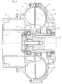
- the hydrodynamic clutch shown in Fig. 1 is a clutch with constant filling. It can be used for example in mining, e.g. B. for agitators, conveyor systems or other difficult starting machines.
- the clutch comprises a pump wheel 1 (primary impeller) with blades 1.1, also a turbine wheel 2 (secondary blade wheel) with blades 2.1.
- the two Paddle wheels 1 and 2 together form a toroidal working space 3.
- a shell 4 is attached to the pump wheel 1. This envelops the turbine wheel 2.
- the turbine wheel 2 is fastened on a hub 5.
- the hub is non-rotatable an output shaft 6 connected.
- Impeller 1 and shell 4 are means Rolling bearings 7 and 8 mounted on the hub 5.
- a delay chamber 9 is attached to the impeller 1 connected. This is via a radially outer and a radially inner one Opening with the work space 3 conductively connected.
- the radially outer opening 10 filling opening
- the radially inner opening 11 leaves a flow of working medium depending on Operating status in both directions, i.e. from the delay chamber 9 in the work room 3 and vice versa.
- the delay chamber 9 has a radially inner wall 9.1 (Ground). As can be seen, the return opening 11 is approximately open the same radius as the floor 9.1. Due to this structural feature the above-mentioned surge is avoided. It takes place when starting the clutch after reaching a certain output speed (depending on filling) uniform filling of the working space 3 from the delay chamber 9 instead of.
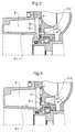
- the variant of a clutch according to the invention shown in FIG. 2 has compared to the embodiment according to FIG. 1, an annular disc 12.
- the Washer 12 has a sealing ring function. It has a bore 11.1. In there is a bore 11.2 in the wall of the pump wheel 1.
- the both holes 11.1 and 11.2 are aligned so that they are together form the return opening mentioned. As you can see, this is also here Return opening approximately at the level of the floor 9.1 Delay chamber 9.
- the bottom is opposite the embodiment 1 radially shifted slightly outwards.
- annular disk 12 intended.
- This in turn also has a channel 11.1, and the Wall of the impeller 1 in turn has a bore 11.2.
- the return opening is thus formed from channel 11.1 and bore 11.2.
- the opening of the return channel is located at about the same radius as the floor 9.1 of the delay chamber 9.
- the delay-side opening of the channel (11.1) in the annular disc (12) lies on a smaller radius than the pump-side opening of the ring channel (11.1).
- the dynamic pressure, the opposing the current is minimal.
- the refill will be close in redirected.
- FIGS. 4 and 5 shows the following:
- the motor rotating and with large slip a relatively large amount of working medium gets out of the working space 3 through the return opening 11 into the delay chamber 9.
Landscapes
- Engineering & Computer Science (AREA)
- General Engineering & Computer Science (AREA)
- Mechanical Engineering (AREA)
- Structures Of Non-Positive Displacement Pumps (AREA)
Applications Claiming Priority (2)
| Application Number | Priority Date | Filing Date | Title |
|---|---|---|---|
| DE19811252A DE19811252A1 (de) | 1998-03-14 | 1998-03-14 | Hydrodynamische Kupplung |
| DE19811252 | 1998-03-14 |
Publications (2)
| Publication Number | Publication Date |
|---|---|
| EP0943830A1 true EP0943830A1 (fr) | 1999-09-22 |
| EP0943830B1 EP0943830B1 (fr) | 2003-08-13 |
Family
ID=7860996
Family Applications (1)
| Application Number | Title | Priority Date | Filing Date |
|---|---|---|---|
| EP99104912A Expired - Lifetime EP0943830B1 (fr) | 1998-03-14 | 1999-03-12 | Accouplement hydrodynamique |
Country Status (2)
| Country | Link |
|---|---|
| EP (1) | EP0943830B1 (fr) |
| DE (2) | DE19811252A1 (fr) |
Cited By (1)
| Publication number | Priority date | Publication date | Assignee | Title |
|---|---|---|---|---|
| RU2426919C2 (ru) * | 2006-04-13 | 2011-08-20 | Фойт Турбо ГмбХ унд Ко.КГ | Гидродинамическая муфта |
Families Citing this family (1)
| Publication number | Priority date | Publication date | Assignee | Title |
|---|---|---|---|---|
| DE102007032212A1 (de) * | 2007-07-11 | 2009-01-15 | Voith Patent Gmbh | Hydrodynamische Kupplung |
Citations (7)
| Publication number | Priority date | Publication date | Assignee | Title |
|---|---|---|---|---|
| BE623071A (fr) * | ||||
| GB994256A (en) | 1964-02-04 | 1965-06-02 | Colette Schuler Voith | Improvements in and relating to hydraulic clutches particularly for electric motor drives |
| DE1425394A1 (de) | 1963-12-02 | 1969-02-13 | Voith Turbo Kg | Stroemungskupplung,insbesondere fuer Antriebe mit Elektromotor |
| DE2202927A1 (de) * | 1971-01-21 | 1972-08-03 | Ferodo Sa | Stroemungskupplung |
| US4581892A (en) * | 1983-05-20 | 1986-04-15 | Bergwerksverband Gmbh | Adjustable fluid coupling |
| EP0512405A1 (fr) * | 1991-05-10 | 1992-11-11 | VOITH TURBO GMBH & CO. KG | Accouplement hydrodynamique |
| DE4311350A1 (en) * | 1993-04-06 | 1993-09-16 | Voith Turbo Kg | Hydrodynamic clutch with automatic torque limiting - has pump impeller and turbine runner wheel forming together annular inner chamber |
Family Cites Families (5)
| Publication number | Priority date | Publication date | Assignee | Title |
|---|---|---|---|---|
| DE883987C (de) * | 1949-06-11 | 1953-07-23 | Voith Gmbh J M | Stroemungskupplung, insbesondere fuer Kraftfahrzeugantrieb mit Verbrennungsmotor und fuer elektrische UEbertragung mit Kurzschlusslaeufermotor |
| DD118456A1 (fr) * | 1975-03-11 | 1976-03-05 | ||
| DE3231368C1 (de) * | 1982-08-24 | 1984-05-24 | Voith-Turbo Gmbh & Co Kg, 7180 Crailsheim | Hydrodynamische Kupplung |
| DE3240334C2 (de) * | 1982-10-30 | 1985-01-24 | Voith-Turbo Gmbh & Co Kg, 7180 Crailsheim | Hydrodynamische Kupplung |
| DD252036A1 (de) * | 1986-08-11 | 1987-12-02 | Stroemungsmasch Veb | Stroemungskupplung |
-
1998
- 1998-03-14 DE DE19811252A patent/DE19811252A1/de not_active Ceased
-
1999
- 1999-03-12 DE DE59906555T patent/DE59906555D1/de not_active Expired - Lifetime
- 1999-03-12 EP EP99104912A patent/EP0943830B1/fr not_active Expired - Lifetime
Patent Citations (8)
| Publication number | Priority date | Publication date | Assignee | Title |
|---|---|---|---|---|
| BE623071A (fr) * | ||||
| DE1425394A1 (de) | 1963-12-02 | 1969-02-13 | Voith Turbo Kg | Stroemungskupplung,insbesondere fuer Antriebe mit Elektromotor |
| GB994256A (en) | 1964-02-04 | 1965-06-02 | Colette Schuler Voith | Improvements in and relating to hydraulic clutches particularly for electric motor drives |
| DE2202927A1 (de) * | 1971-01-21 | 1972-08-03 | Ferodo Sa | Stroemungskupplung |
| US4581892A (en) * | 1983-05-20 | 1986-04-15 | Bergwerksverband Gmbh | Adjustable fluid coupling |
| EP0512405A1 (fr) * | 1991-05-10 | 1992-11-11 | VOITH TURBO GMBH & CO. KG | Accouplement hydrodynamique |
| EP0512405B1 (fr) | 1991-05-10 | 1994-09-14 | VOITH TURBO GMBH & CO. KG | Accouplement hydrodynamique |
| DE4311350A1 (en) * | 1993-04-06 | 1993-09-16 | Voith Turbo Kg | Hydrodynamic clutch with automatic torque limiting - has pump impeller and turbine runner wheel forming together annular inner chamber |
Cited By (1)
| Publication number | Priority date | Publication date | Assignee | Title |
|---|---|---|---|---|
| RU2426919C2 (ru) * | 2006-04-13 | 2011-08-20 | Фойт Турбо ГмбХ унд Ко.КГ | Гидродинамическая муфта |
Also Published As
| Publication number | Publication date |
|---|---|
| EP0943830B1 (fr) | 2003-08-13 |
| DE59906555D1 (de) | 2003-09-18 |
| DE19811252A1 (de) | 1999-10-07 |
Similar Documents
| Publication | Publication Date | Title |
|---|---|---|
| EP0324152B1 (fr) | Embrayage à fluide | |
| DE2745936A1 (de) | Viskositaets-stroemungsmittelkupplung | |
| DE3800045C2 (de) | Kraftübertragungseinrichtung für ein vierrad-getriebenes Fahrzeug | |
| DE10154286A1 (de) | Drehmomentwandler | |
| DE3841237C2 (de) | Flügelzellenpumpen-Getriebekupplung für vierradgetriebene Fahrzeuge | |
| DE102017006807A1 (de) | Antriebseinrichtung für ein Kraftfahrzeug, insbesondere für einen Kraftwagen | |
| DE69913452T2 (de) | Abgestufte Dichtung und Buchse | |
| DE4209372B4 (de) | Hydraulische Bremseinrichtung für Fahrzeuge | |
| DE8908357U1 (de) | Flüssigkeitsreibungskupplung | |
| DE60029425T2 (de) | Motor mit symmetrischem bremssystem | |
| DE60210383T2 (de) | Hydrodynamische Vorrichtung mit Überbrückungskupplung | |
| DE3831937A1 (de) | Fluiddichtungsvorrichtung | |
| EP0943830B1 (fr) | Accouplement hydrodynamique | |
| DE3240334A1 (de) | Hydrodynamische kupplung | |
| DE602004002493T2 (de) | Flüssigkeitskupplung | |
| DE2208502C3 (de) | Fahrzeugwechselgetriebe | |
| DE19508458A1 (de) | Drehmomentwandler mit darin enthaltenem Verzögerungsmechanismus | |
| DE68901802T2 (de) | Fluessigkeitsreibungsskupplung. | |
| DE102007003055A1 (de) | Hydrodynamischer Drehmomentwandler | |
| DE2627543A1 (de) | Kolbendichtungen fuer drehvorrichtungen | |
| DE10004952C2 (de) | Überbrückungsvorrichtung für einen Drehmomentwandler | |
| DE102009026706A1 (de) | Lageranordnung für eine Welle | |
| DE2216251A1 (de) | Kupplungseinheit | |
| DE2359894A1 (de) | Hydrodynamische einheit, insbesondere fuer kraftfahrzeuge | |
| DE602004002121T2 (de) | Flüssigkeitskupplung |
Legal Events
| Date | Code | Title | Description |
|---|---|---|---|
| PUAI | Public reference made under article 153(3) epc to a published international application that has entered the european phase |
Free format text: ORIGINAL CODE: 0009012 |
|
| AK | Designated contracting states |
Kind code of ref document: A1 Designated state(s): DE FR GB IT |
|
| AX | Request for extension of the european patent |
Free format text: AL;LT;LV;MK;RO;SI |
|
| 17P | Request for examination filed |
Effective date: 19991001 |
|
| AKX | Designation fees paid |
Free format text: DE FR GB IT |
|
| 17Q | First examination report despatched |
Effective date: 20010716 |
|
| GRAH | Despatch of communication of intention to grant a patent |
Free format text: ORIGINAL CODE: EPIDOS IGRA |
|
| GRAH | Despatch of communication of intention to grant a patent |
Free format text: ORIGINAL CODE: EPIDOS IGRA |
|
| GRAA | (expected) grant |
Free format text: ORIGINAL CODE: 0009210 |
|
| AK | Designated contracting states |
Designated state(s): DE FR GB IT |
|
| REG | Reference to a national code |
Ref country code: GB Ref legal event code: FG4D Free format text: NOT ENGLISH |
|
| REF | Corresponds to: |
Ref document number: 59906555 Country of ref document: DE Date of ref document: 20030918 Kind code of ref document: P |
|
| GBT | Gb: translation of ep patent filed (gb section 77(6)(a)/1977) |
Effective date: 20031117 |
|
| ET | Fr: translation filed | ||
| PLBE | No opposition filed within time limit |
Free format text: ORIGINAL CODE: 0009261 |
|
| STAA | Information on the status of an ep patent application or granted ep patent |
Free format text: STATUS: NO OPPOSITION FILED WITHIN TIME LIMIT |
|
| 26N | No opposition filed |
Effective date: 20040514 |
|
| PGFP | Annual fee paid to national office [announced via postgrant information from national office to epo] |
Ref country code: IT Payment date: 20120323 Year of fee payment: 14 |
|
| PGFP | Annual fee paid to national office [announced via postgrant information from national office to epo] |
Ref country code: GB Payment date: 20130326 Year of fee payment: 15 |
|
| PGFP | Annual fee paid to national office [announced via postgrant information from national office to epo] |
Ref country code: DE Payment date: 20130424 Year of fee payment: 15 |
|
| PGFP | Annual fee paid to national office [announced via postgrant information from national office to epo] |
Ref country code: FR Payment date: 20130419 Year of fee payment: 15 |
|
| REG | Reference to a national code |
Ref country code: DE Ref legal event code: R119 Ref document number: 59906555 Country of ref document: DE |
|
| GBPC | Gb: european patent ceased through non-payment of renewal fee |
Effective date: 20140312 |
|
| REG | Reference to a national code |
Ref country code: FR Ref legal event code: ST Effective date: 20141128 |
|
| REG | Reference to a national code |
Ref country code: DE Ref legal event code: R119 Ref document number: 59906555 Country of ref document: DE Effective date: 20141001 |
|
| PG25 | Lapsed in a contracting state [announced via postgrant information from national office to epo] |
Ref country code: FR Free format text: LAPSE BECAUSE OF NON-PAYMENT OF DUE FEES Effective date: 20140331 Ref country code: DE Free format text: LAPSE BECAUSE OF NON-PAYMENT OF DUE FEES Effective date: 20141001 Ref country code: GB Free format text: LAPSE BECAUSE OF NON-PAYMENT OF DUE FEES Effective date: 20140312 |
|
| PG25 | Lapsed in a contracting state [announced via postgrant information from national office to epo] |
Ref country code: IT Free format text: LAPSE BECAUSE OF NON-PAYMENT OF DUE FEES Effective date: 20140312 |