EP0943843A2 - Dispositif de sélection pour une transmission automatique d'un véhicule - Google Patents
Dispositif de sélection pour une transmission automatique d'un véhicule Download PDFInfo
- Publication number
- EP0943843A2 EP0943843A2 EP99105612A EP99105612A EP0943843A2 EP 0943843 A2 EP0943843 A2 EP 0943843A2 EP 99105612 A EP99105612 A EP 99105612A EP 99105612 A EP99105612 A EP 99105612A EP 0943843 A2 EP0943843 A2 EP 0943843A2
- Authority
- EP
- European Patent Office
- Prior art keywords
- selector lever
- selector
- lever
- automatic transmission
- signal
- Prior art date
- Legal status (The legal status is an assumption and is not a legal conclusion. Google has not performed a legal analysis and makes no representation as to the accuracy of the status listed.)
- Granted
Links
Images


Classifications
-
- F—MECHANICAL ENGINEERING; LIGHTING; HEATING; WEAPONS; BLASTING
- F16—ENGINEERING ELEMENTS AND UNITS; GENERAL MEASURES FOR PRODUCING AND MAINTAINING EFFECTIVE FUNCTIONING OF MACHINES OR INSTALLATIONS; THERMAL INSULATION IN GENERAL
- F16H—GEARING
- F16H61/00—Control functions within control units of change-speed- or reversing-gearings for conveying rotary motion ; Control of exclusively fluid gearing, friction gearing, gearings with endless flexible members or other particular types of gearing
- F16H61/22—Locking of the control input devices
-
- F—MECHANICAL ENGINEERING; LIGHTING; HEATING; WEAPONS; BLASTING
- F16—ENGINEERING ELEMENTS AND UNITS; GENERAL MEASURES FOR PRODUCING AND MAINTAINING EFFECTIVE FUNCTIONING OF MACHINES OR INSTALLATIONS; THERMAL INSULATION IN GENERAL
- F16H—GEARING
- F16H59/00—Control inputs to control units of change-speed- or reversing-gearings for conveying rotary motion
- F16H59/02—Selector apparatus
- F16H59/0204—Selector apparatus for automatic transmissions with means for range selection and manual shifting, e.g. range selector with tiptronic
-
- F—MECHANICAL ENGINEERING; LIGHTING; HEATING; WEAPONS; BLASTING
- F16—ENGINEERING ELEMENTS AND UNITS; GENERAL MEASURES FOR PRODUCING AND MAINTAINING EFFECTIVE FUNCTIONING OF MACHINES OR INSTALLATIONS; THERMAL INSULATION IN GENERAL
- F16H—GEARING
- F16H59/00—Control inputs to control units of change-speed- or reversing-gearings for conveying rotary motion
- F16H59/02—Selector apparatus
- F16H2059/0239—Up- and down-shift or range or mode selection by repeated movement
-
- F—MECHANICAL ENGINEERING; LIGHTING; HEATING; WEAPONS; BLASTING
- F16—ENGINEERING ELEMENTS AND UNITS; GENERAL MEASURES FOR PRODUCING AND MAINTAINING EFFECTIVE FUNCTIONING OF MACHINES OR INSTALLATIONS; THERMAL INSULATION IN GENERAL
- F16H—GEARING
- F16H61/00—Control functions within control units of change-speed- or reversing-gearings for conveying rotary motion ; Control of exclusively fluid gearing, friction gearing, gearings with endless flexible members or other particular types of gearing
- F16H61/22—Locking of the control input devices
- F16H2061/223—Electrical gear shift lock, e.g. locking of lever in park or neutral position by electric means if brake is not applied; Key interlock, i.e. locking the key if lever is not in park position
-
- F—MECHANICAL ENGINEERING; LIGHTING; HEATING; WEAPONS; BLASTING
- F16—ENGINEERING ELEMENTS AND UNITS; GENERAL MEASURES FOR PRODUCING AND MAINTAINING EFFECTIVE FUNCTIONING OF MACHINES OR INSTALLATIONS; THERMAL INSULATION IN GENERAL
- F16H—GEARING
- F16H59/00—Control inputs to control units of change-speed- or reversing-gearings for conveying rotary motion
- F16H59/02—Selector apparatus
- F16H59/08—Range selector apparatus
- F16H59/10—Range selector apparatus comprising levers
-
- F—MECHANICAL ENGINEERING; LIGHTING; HEATING; WEAPONS; BLASTING
- F16—ENGINEERING ELEMENTS AND UNITS; GENERAL MEASURES FOR PRODUCING AND MAINTAINING EFFECTIVE FUNCTIONING OF MACHINES OR INSTALLATIONS; THERMAL INSULATION IN GENERAL
- F16H—GEARING
- F16H59/00—Control inputs to control units of change-speed- or reversing-gearings for conveying rotary motion
- F16H59/36—Inputs being a function of speed
- F16H59/44—Inputs being a function of speed dependent on machine speed, e.g. the vehicle speed
Definitions
- the invention relates to a selection device for an automatic transmission of a motor vehicle.
- selector devices which are connected to the motor vehicle transmission via linkage, cable pulls or other mechanical transmission elements, the actuating forces to be used for gear selection are predetermined in construction.
- the driver When selecting a gear, the driver must overcome a resistance that gives him a feeling of shifting. The engagement of a gear is therefore noticeable for him.
- electronically controlled selector devices for motor vehicle transmissions which are mechanically decoupled from the motor-transmission unit, the forces to be shifted are often simulated in order to give the vehicle driver a feeling of shifting.
- EP 0 620 385 A1 describes a selector device for an automatic transmission of a motor vehicle known, which is mounted in a housing pivotable about a first axis Cross piece in which a selector lever pivotally mounted about a second axis is recorded.
- the swivel axes are approximately orthogonal, but spatial staggered.
- Spring-loaded locking means are on the selector lever provided that interact with an increasing contour of the cross piece. The Movements of the selector lever are detected by sensors and in control electronics processed.
- DE 40 29 330 A1 also shows a selection device in which one is an axis articulated on the selector lever and positioned resiliently against a locking member Jack is provided with a profiled surface and for fixing the selector lever in one of the two shift gates serves, the first shift gate (automatic shift gate) to select all automatic shift functions, including reverse gear, and the second shift gate (step shift gate) provided for manual step-by-step switching is.
- EP 0 568 928 A1 there is a selection device with one in a housing a cross piece pivotally mounted selector lever described, with the cross piece a sleeve-shaped part is connected, which the positioning of the selector lever in the selector and shift lanes by the interaction of one in the sleeve-shaped part used, spring-loaded locking means with a profiled surface on the housing the dialer allows. An automatic return of the selector lever to his Starting position is not apparent from the script.
- the invention is based on the technical problem, a selection device for To create automatic transmission of a motor vehicle without mechanical transmission elements The greatest possible security against incorrect operation with a simple structure guaranteed and has low manufacturing tolerances.
- a selection device for an automatic transmission of motor vehicles then consists of a housing and one in the housing around a first, axis arranged approximately in the transverse direction of the vehicle (selection axis) can be pivoted stored, multifunctional cross piece.
- the cross piece is multifunctional because of it fulfills several functions within the voting device.
- a second axis (pivot axis) is mounted in the cross piece and pivots the selector lever in the cross piece. Both axes are approximately orthogonal, but are spatially offset from one another.
- the selector lever can be swiveled together with the crosspiece around the first axis to select the automatic speed steps (in this case P, R, N, D). It is guided within an automatic shift gate.
- at least one of the selector lever positions (P, R, N, D) forms a transverse lane in which the selector lever can be pivoted about the second axis, approximately in the transverse direction of the vehicle.
- the selector lever has at least one spring-loaded contour roller which interacts with a contour incorporated into the crosspiece.
- a contour roller is understood here to mean, for example, a spring-loaded rolling element which is received in a cage and guided therein and rolls on the contour. In the simplest case, a ball can serve as the rolling element. Furthermore, a spring-loaded latching of the cross piece relative to the housing is provided.
- mutually independent means are required for the permanent detection of signals of the speed of the vehicle, the brake signal and the selector lever position, the signals being forwarded to a central processing unit (CPU) after their detection.
- the processing unit controls an electromagnet, the activated armature of which engages directly or indirectly in a recess in the crosspiece and thus blocks the selection of certain speed steps.
- the armature of the electromagnet is used as an active element, while in the case of indirect intervention, an intermediate element cooperating with the armature locks the selector lever in the positions provided for this purpose.
- a selector device has means which directly or indirectly secure the ignition key in the ignition lock, as long as the selector lever is in positions which correspond to the speed steps which are provided for the locomotion of the vehicle.
- the ignition key can therefore only be removed in the selector lever position "P" if the ignition of the vehicle is also switched off, that is to say the power supply is interrupted.
- the connection between the selector and the ignition lock can be established in a manner known per se via a cable or via a linkage.
- a selector device has a link guiding the selector lever and passing through it, which is attached below an upper housing cover or incorporated into it.
- the blind can be moved in a guide located below the housing cover in the housing synchronously with the selector lever.
- a circuit board with signal sensors assigned to the respective switching positions is inserted below the housing cover. Under the signal sensors, the selector lever is used to move signal sensors past the signal sensors without contact.
- the signal transmitters can be arranged on the top of the blind. Of course, the reverse arrangement is also possible. For example, it is conceivable to arrange the signal transmitters on the circuit board and to move the signal recorders past the signal transmitters with the selector lever.
- a particularly advantageous feature of the invention consists in one piece executed cross piece molded teeth, which with a on the bottom of the Shaped or assembled complementary toothing interacts. This can ensure that the blinds are kink-free and very even larger distances can be performed, which is the result of conventional solutions the often very soft blinds are not possible. They also play a role Component and manufacturing tolerances that arise during production are now only a subordinate one Role if such gearing is used.
- a selection device for an automatic transmission of motor vehicles in automatic mode only 4 speed steps, namely the automatic speed steps D, N, R, P.
- the speed levels should also be arranged in this order. Out this arrangement is understandable that several locking functions of the selector lever with only one electromagnet can be realized. This is a significant cost advantage of such a solution.
- Electromagnets can be used that have a pressure anchor or a tie rod exhibit. According to the invention, these are electromagnets, in which either the activated one Anchor is a retracted pressure anchor in the de-energized state, or where the activated armature of the electromagnet a retracted tie rod when energized is.
- a lever When using an electromagnet with tie rod, a lever passes through a recess of the cross piece with its hook-shaped section, so that the cross piece is prevented from pivoting in the direction of the reverse gear "R". This serves to prevent the inadvertent selection of the reverse gear “R” from the selector lever positions "N” and “D”.
- the electromagnet is activated during driving, which means that the spring-loaded armature is retracted against the pressure of a spring.
- the spring only serves for the automatic extension movement of the armature as soon as the power supply is interrupted.
- the anchor interacts with a lever mechanism that contains the lever described above.
- the lever can be pivoted about an axis. Of course, it is within the scope of the inventive concept to pivot the lever directly into the pivoting area of the cross piece and thus to effectively prevent the selector lever from moving into the reverse gear "R”.
- a further, very advantageous embodiment of the inventive concept provides for a lever arm to be formed on the cross piece, in which at least two recesses are formed.
- a recess is preferably to be understood as a trough-like depression in the lever arm.
- the armature of the electromagnet engages in driving operation directly in one of these recesses on the lever arm of the cross piece, so that the movement of the selector lever from the "D” or “N” gear stage into the reverse gear R is effectively prevented.
- a change between "D” and “N” is still possible.
- the electromagnet is detected by a motor vehicle transmission Speed signal without current when the speed of the motor vehicle is lower or is equal to 4 km / h.
- the recess in the cross piece released so that the reverse gear "R" can be selected.
- the selector lever in the selector lever position "P" can be blocked by the extended armature of the energized electromagnet.
- the anchor engages directly in a further recess on the lever arm of the cross piece.
- the selector lever also moves through the blinds guided slide that carries auto switches attached to its surface.
- These signalers generate the signals for on the signal pickups assigned on the circuit board the stepping mode.
- contactless signal transmitters respectively Manufacturing tolerances between the components are irrelevant. This can compensate for the distance between signal generators and signal sensors become.
- the crosspiece is furthermore a cam is formed, which in the selector lever position "P" with one around an axis pivotable lever arm cooperates, which connects via a transmission element creates the ignition lock of the motor vehicle, so that the ignition key only in the parking position "P" is released from the ignition lock.
- the driver's lack of shifting sensation in the case of electronic signal scanning can, for example, also in automatic switching mode by a spring-loaded detent can be simulated in the manner of a spring rolling element detent, the rolling element for example is attached to the cross piece and in a contour corresponding to the speed steps in unrolls the housing or vice versa.
- the structure of the locking means largely corresponds the contour roller described above.
- a holder for a mechanical Transmission element may be present, for example a linkage or a Cable is.
- this is only necessary if statutory regulations provide an additional one mechanical connection to the motor vehicle transmission.
- the technical problem according to the invention is not a mechanical connection necessary.
- Signal pickups and Signal generator used that generate or record electromagnetic signals and are, for example, Hall sensors.
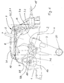
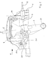
- a selector device according to the invention for an automatic transmission of a motor vehicle is shown by way of example in FIGS. 1-4.
- the shown selection device for an automatic transmission of motor vehicles consists of a housing 1, as well as a multifunctional cross piece 3 pivotably mounted in the housing about a first axis 2 arranged approximately in the transverse direction of the vehicle, in which a selector lever 5 pivotably mounted about a second axis 4 is received , the axes being approximately orthogonal but spatially offset from one another.
- the selector device has an automatic shift gate, in which the individual driving stages P, R, N, D of the automatic transmission can be selected by pivoting the selector lever about the first axis 2 (automatic shift operation), at least one of these selector lever positions forming a transverse alley in which a pivoting of the Selector lever around the second axis 4, approximately in the transverse direction of the vehicle, is possible and by manual, tip-wise pivoting of the selector lever from a neutral central position in one direction an upshift by one gear and in the opposite direction a downshift by one gear, the Selector lever automatically returns to its neutral center position (stepping mode).
- an automatic shift gate in which the individual driving stages P, R, N, D of the automatic transmission can be selected by pivoting the selector lever about the first axis 2 (automatic shift operation), at least one of these selector lever positions forming a transverse alley in which a pivoting of the Selector lever around the second axis 4, approximately in the transverse direction of the vehicle, is possible and by manual, tip-wise
- At least one spring-loaded contour roller 6 is present on the selector lever 5, which cooperates with a contour 3.1 of the cross piece 3 during the manual, tip-wise pivoting of the selector lever and thus also supports the return movement of the selector lever into its neutral central position. Furthermore, a spring-loaded latching of the cross piece relative to the housing is provided.
- Mutually independent means for the permanent detection of signals of the speed of the vehicle, the brake signal and the selector lever position pass the detected signals on to a central processing unit which controls an electromagnet 13, the activated armature 13.1 of which engages directly in a recess 3.3 or 3.5 on the crosspiece 3 and thus blocked the selection of certain speed levels.
- the armature 13.1 engages in the recess 3.3 of a lever arm 3.6 formed on the cross piece 3.
- the armature 13.1 engages in the recess 3.5 of the lever arm 3.6 formed on the cross piece 3.
- the selector lever 5 can be pivoted in the latter engagement of the armature 13.1 between the selector lever positions "N" and "D". An unintentional selection of the reverse gear "R” is effectively prevented.
- means 3.4, 14 and 15 are available to secure the ignition key in the ignition lock.
- the selector lever 5 passes through a backdrop 7.1 and is simultaneously guided by this backdrop.
- the backdrop is incorporated into an upper housing cover 7.
- the signal transmitters are arranged on a below the housing cover Printed circuit board 10 and signal transducers mounted thereon moved past without contact, the signal transducers being assigned to the respective switching positions.
- a toothing 3.2 is formed in the upper area facing the blind, which interacts with a complementary toothing 8.2 attached to the underside 8.1 of the blind 8.
- the automatic speed stages are arranged in the order D, N, R, P in the embodiment shown.
- the activated armature 13.1 of the electromagnet 13 is in the present case a pressure armature which is drawn in in the currentless state.
- the activated, ie energized electromagnet 13 accordingly has an extended armature 13.1
- the electromagnet 13 is de-energized by a speed signal detected on the motor vehicle transmission when the speed of the motor vehicle is less than or equal to 4 km / h.
- the recess 3.5 is released at a speed of less than or equal to 4 km / h.
- the selector lever In the selector lever position "P", the selector lever is blocked by the extended armature 13.1 of the energized electromagnet 13, because the armature engages in the recess 3.3 on the lever arm 3.6 of the crosspiece 3 until a brake signal detected by the central processing unit, the electromagents, when the brake is actuated 13 controls such that the current supply is interrupted and the retracted armature 13.1 of the electromagnet 13 releases the selector lever in the selector lever position "P" again.
- FIG. 5 shows a further advantageous embodiment of a selection device according to the invention for an automatic transmission of motor vehicles, in which the activated armature 13. 1 of the electromagnet 13 is a tension rod drawn in when the current is applied. This means that the armature is extended when the power supply is interrupted. To prevent the inadvertent selection of the reverse gear “R”, the electromagnet 13 is activated during driving and the spring-loaded armature 13.1, which is drawn in against the pressure of a spring, interacts with a lever mechanism.
- the armature actuates a lever 21 which can be pivoted about an axis 22 and which, in the driving stages "N” and “D”, engages through a recess 23 in the cross piece 3 and fixes the cross piece 3 in one direction with a hook-shaped section.
- the selector lever can still be pivoted between the selector lever positions “N” and “D”, but inadvertent engagement of the reverse gear “R” is effectively prevented.
- the selector lever 5 also passes through a slide 17, which is guided transversely in the blind 8 and which carries signal transmitters 12 fastened on its surface, which transmit the signals for detection to the assigned signal receivers 11 on the printed circuit board 10 the step-by-step operation of the selector lever 5, ie the movement of the selector lever approximately in the vehicle transverse direction.
- a receptacle 20 for a mechanical transmission element which can be, for example, a linkage or a cable pull.
Landscapes
- Engineering & Computer Science (AREA)
- General Engineering & Computer Science (AREA)
- Mechanical Engineering (AREA)
- Arrangement Or Mounting Of Control Devices For Change-Speed Gearing (AREA)
- Control Of Transmission Device (AREA)
Applications Claiming Priority (2)
| Application Number | Priority Date | Filing Date | Title |
|---|---|---|---|
| DE19811972 | 1998-03-19 | ||
| DE1998111972 DE19811972C2 (de) | 1998-03-19 | 1998-03-19 | Wählvorrichtung für ein Automatikgetriebe eines Kraftfahrzeuges |
Publications (3)
| Publication Number | Publication Date |
|---|---|
| EP0943843A2 true EP0943843A2 (fr) | 1999-09-22 |
| EP0943843A3 EP0943843A3 (fr) | 2000-03-29 |
| EP0943843B1 EP0943843B1 (fr) | 2002-05-08 |
Family
ID=7861464
Family Applications (1)
| Application Number | Title | Priority Date | Filing Date |
|---|---|---|---|
| EP19990105612 Expired - Lifetime EP0943843B1 (fr) | 1998-03-19 | 1999-03-19 | Dispositif de sélection pour une transmission automatique d'un véhicule |
Country Status (3)
| Country | Link |
|---|---|
| EP (1) | EP0943843B1 (fr) |
| DE (1) | DE19811972C2 (fr) |
| ES (1) | ES2175866T3 (fr) |
Cited By (4)
| Publication number | Priority date | Publication date | Assignee | Title |
|---|---|---|---|---|
| WO2001059333A1 (fr) * | 2000-02-08 | 2001-08-16 | ZF Lemförder Metallwaren AG | Dispositif de changement de vitesses pour une boite de vitesses automatique |
| WO2001073320A1 (fr) * | 2000-03-28 | 2001-10-04 | ZF Lemförder Metallwaren AG | Dispositif de changement de vitesses pour une boite automatique d'un vehicule automobile |
| WO2007065656A1 (fr) * | 2005-12-06 | 2007-06-14 | Fico Cables, S.A. | Module de changement de vitesses |
| FR3059755A1 (fr) * | 2016-12-06 | 2018-06-08 | Peugeot Citroen Automobiles Sa | Dispositif de controle du passage des rapports d'une boite de vitesses manuelle de vehicule en fonction de la vitesse |
Families Citing this family (3)
| Publication number | Priority date | Publication date | Assignee | Title |
|---|---|---|---|---|
| EP1138984B1 (fr) | 2000-03-28 | 2004-08-04 | Preh GmbH | Dispositif de levier sélecteur pour boíte de vitesses dans un véhicule |
| DE102004030152A1 (de) * | 2004-06-22 | 2006-01-19 | Daimlerchrysler Ag | Handwählhebel |
| CN114967833B (zh) * | 2022-06-02 | 2025-08-05 | 东风延锋汽车座椅有限公司 | 一种双向多档调节的自复位机械手柄 |
Citations (3)
| Publication number | Priority date | Publication date | Assignee | Title |
|---|---|---|---|---|
| DE4029330A1 (de) | 1990-09-15 | 1992-03-26 | Porsche Ag | Schaltvorrichtung fuer ein kraftfahrzeuggetriebe |
| EP0568928A1 (fr) | 1992-05-08 | 1993-11-10 | FUJI KIKO CO., Ltd. | Dispositif de changement de vitesses |
| EP0620385A1 (fr) | 1993-04-13 | 1994-10-19 | Jaeger | Ensemble de commande pour boîte de vitesses mécanique et système de commande incorporant celui-ci |
Family Cites Families (8)
| Publication number | Priority date | Publication date | Assignee | Title |
|---|---|---|---|---|
| US4967883A (en) * | 1988-06-23 | 1990-11-06 | Kabushiki Kaisha Tokai-Rika-Denki-Seisakusho | Automatic transmission shift lever device with park and ignition interlock |
| DE4003281A1 (de) * | 1990-02-03 | 1991-08-08 | Bayerische Motoren Werke Ag | Vorrichtung fuer das anzeigen der eingelegten gangstufe eines kraftfahrzeuggetriebes |
| DE4445925C1 (de) * | 1994-12-22 | 1996-05-15 | Lemfoerder Metallwaren Ag | Schlitzabdeckung für ein geschlitztes Gehäuse einer Außenschaltung eines Kraftfahrzeuges mit automatischem Getriebe |
| DE19526059C2 (de) * | 1995-07-17 | 1999-05-27 | Lemfoerder Metallwaren Ag | Schaltvorrichtung für ein automatisches Getriebe eines Kraftfahrzeugs |
| US5899115A (en) * | 1995-10-24 | 1999-05-04 | Fuji Kiko Co., Ltd. | Shift select lever device for automatic transmission |
| DE19601442C2 (de) * | 1996-01-17 | 1998-02-19 | Lemfoerder Metallwaren Ag | Wählhebelsperre für eine Schaltung eines automatichen Getriebes in einem Kraftfahrzeug |
| US5647465A (en) * | 1996-03-14 | 1997-07-15 | General Motors Corporation | Transmission shift lever and brake interlock control assembly |
| DE19610766C2 (de) * | 1996-03-19 | 1998-12-10 | Daimler Benz Ag | Wähl- und Schalteinrichtung für ein Gangwechselgetriebe |
-
1998
- 1998-03-19 DE DE1998111972 patent/DE19811972C2/de not_active Expired - Fee Related
-
1999
- 1999-03-19 ES ES99105612T patent/ES2175866T3/es not_active Expired - Lifetime
- 1999-03-19 EP EP19990105612 patent/EP0943843B1/fr not_active Expired - Lifetime
Patent Citations (3)
| Publication number | Priority date | Publication date | Assignee | Title |
|---|---|---|---|---|
| DE4029330A1 (de) | 1990-09-15 | 1992-03-26 | Porsche Ag | Schaltvorrichtung fuer ein kraftfahrzeuggetriebe |
| EP0568928A1 (fr) | 1992-05-08 | 1993-11-10 | FUJI KIKO CO., Ltd. | Dispositif de changement de vitesses |
| EP0620385A1 (fr) | 1993-04-13 | 1994-10-19 | Jaeger | Ensemble de commande pour boîte de vitesses mécanique et système de commande incorporant celui-ci |
Cited By (7)
| Publication number | Priority date | Publication date | Assignee | Title |
|---|---|---|---|---|
| WO2001059333A1 (fr) * | 2000-02-08 | 2001-08-16 | ZF Lemförder Metallwaren AG | Dispositif de changement de vitesses pour une boite de vitesses automatique |
| US6684730B2 (en) | 2000-02-08 | 2004-02-03 | ZF Lemförder Metallwaren AG | Gear shift device for an automatic transmission |
| WO2001073320A1 (fr) * | 2000-03-28 | 2001-10-04 | ZF Lemförder Metallwaren AG | Dispositif de changement de vitesses pour une boite automatique d'un vehicule automobile |
| US6708581B1 (en) | 2000-03-28 | 2004-03-23 | ZF Lemförder Metallwaren AG | Shifting device for an automatic gearbox in a motor vehicle |
| WO2007065656A1 (fr) * | 2005-12-06 | 2007-06-14 | Fico Cables, S.A. | Module de changement de vitesses |
| FR3059755A1 (fr) * | 2016-12-06 | 2018-06-08 | Peugeot Citroen Automobiles Sa | Dispositif de controle du passage des rapports d'une boite de vitesses manuelle de vehicule en fonction de la vitesse |
| EP3333461A1 (fr) * | 2016-12-06 | 2018-06-13 | PSA Automobiles SA | Dispositif de contrôle du passage des rapports d'une boîte de vitesses manuelle de véhicule en fonction de la vitesse |
Also Published As
| Publication number | Publication date |
|---|---|
| EP0943843A3 (fr) | 2000-03-29 |
| ES2175866T3 (es) | 2002-11-16 |
| DE19811972A1 (de) | 1999-10-14 |
| DE19811972C2 (de) | 2000-01-13 |
| EP0943843B1 (fr) | 2002-05-08 |
Similar Documents
| Publication | Publication Date | Title |
|---|---|---|
| DE4426207C5 (de) | Wähleinrichtung für ein Automatikgetriebe eines Kraftfahrzeugs | |
| DE102005041569B4 (de) | Gangschaltungsvorrichtung und Verfahren zum Steuern derselben | |
| DE69404753T2 (de) | Parkverriegelungs-Mechanismus für Kraftfahrzeuge | |
| EP1165988B1 (fr) | Dispositif de changement de vitesses pour une boite de vitesses automatique | |
| DE69615624T2 (de) | Getriebeschalthebel | |
| EP0175061A1 (fr) | Transmetteur pour la boîte de vitesse d'un véhicule automobile | |
| EP1464875A2 (fr) | Dispositif de changement de vitesse monostable avec P-position | |
| EP0953790A2 (fr) | Dispositif de sélection pour une transmission automatique de véhicule automobile | |
| DE10315643B3 (de) | Shift by wire-Schaltung mit P-Position | |
| DE10140164A1 (de) | Steuereinheit für die Gang- oder Schaltprogrammwahl eines automatischen Kraftfahrzeuggetriebes | |
| EP0943843B1 (fr) | Dispositif de sélection pour une transmission automatique d'un véhicule | |
| DE10361209B3 (de) | Vorrichtung zum Umschalten eines mechanischen Schaltmittels | |
| DE60109315T2 (de) | Vorrichtung zur bedienung eines schaltgetriebes und verfahren eines pulssteuerung | |
| DE10015079C2 (de) | Schaltvorrichtung für ein Automatikgetriebe eines Kraftfahrzeuges | |
| DE19850374B4 (de) | Kraftfahrzeug mit einem Antriebsmotor und einem automatisch geschalteten Getriebe mit einer Wähleinrichtung | |
| EP0782510A1 (fr) | Commutateur monte sur la colonne de direction, servant d'organe de changement de vitesses avec possibilite de fixation en position neutre | |
| DE3911570C1 (fr) | ||
| DE10057299A1 (de) | Schaltvorrichtung für ein Automatikgetriebe eines Kraftfahrzeugs | |
| EP0754887B1 (fr) | Dispositif de verrouillage du levier de sélection d'un véhicule automobile équipé d'une transmission automatique | |
| DE19737366A1 (de) | Schaltvorrichtung für Automatikgetriebe | |
| DE29923633U1 (de) | Aktuator für ein mit elektrischer Betätigung versehenes Automatikgetriebe | |
| DE10146775B4 (de) | Wahlhebelsicherung für einen Wahlhebel eines Automatikgetriebes | |
| DE10040077A1 (de) | Aktuator zur Betätigung einer mit einem Hydraulik-Wählschieber gekoppelten Parksperreneinrichtung | |
| DE19815676A1 (de) | Anfahrschutz | |
| DE19855951A1 (de) | Automatisiertes Drehmomentübertragungssystem für Kraftfahrzeuge |
Legal Events
| Date | Code | Title | Description |
|---|---|---|---|
| PUAI | Public reference made under article 153(3) epc to a published international application that has entered the european phase |
Free format text: ORIGINAL CODE: 0009012 |
|
| AK | Designated contracting states |
Kind code of ref document: A2 Designated state(s): BE ES FR GB IT NL SE |
|
| AX | Request for extension of the european patent |
Free format text: AL;LT;LV;MK;RO;SI |
|
| PUAL | Search report despatched |
Free format text: ORIGINAL CODE: 0009013 |
|
| AK | Designated contracting states |
Kind code of ref document: A3 Designated state(s): AT BE CH CY DE DK ES FI FR GB GR IE IT LI LU MC NL PT SE |
|
| AX | Request for extension of the european patent |
Free format text: AL;LT;LV;MK;RO;SI |
|
| RAP1 | Party data changed (applicant data changed or rights of an application transferred) |
Owner name: ZF LEMFOERDER METALLWAREN AG |
|
| 17P | Request for examination filed |
Effective date: 20000524 |
|
| AKX | Designation fees paid |
Free format text: BE ES FR GB IT NL SE |
|
| REG | Reference to a national code |
Ref country code: DE Ref legal event code: 8566 |
|
| GRAG | Despatch of communication of intention to grant |
Free format text: ORIGINAL CODE: EPIDOS AGRA |
|
| GRAG | Despatch of communication of intention to grant |
Free format text: ORIGINAL CODE: EPIDOS AGRA |
|
| GRAH | Despatch of communication of intention to grant a patent |
Free format text: ORIGINAL CODE: EPIDOS IGRA |
|
| 17Q | First examination report despatched |
Effective date: 20011002 |
|
| GRAH | Despatch of communication of intention to grant a patent |
Free format text: ORIGINAL CODE: EPIDOS IGRA |
|
| REG | Reference to a national code |
Ref country code: GB Ref legal event code: IF02 |
|
| GRAA | (expected) grant |
Free format text: ORIGINAL CODE: 0009210 |
|
| AK | Designated contracting states |
Kind code of ref document: B1 Designated state(s): BE ES FR GB IT NL SE |
|
| GBT | Gb: translation of ep patent filed (gb section 77(6)(a)/1977) |
Effective date: 20020509 |
|
| ET | Fr: translation filed | ||
| REG | Reference to a national code |
Ref country code: ES Ref legal event code: FG2A Ref document number: 2175866 Country of ref document: ES Kind code of ref document: T3 |
|
| PLBE | No opposition filed within time limit |
Free format text: ORIGINAL CODE: 0009261 |
|
| STAA | Information on the status of an ep patent application or granted ep patent |
Free format text: STATUS: NO OPPOSITION FILED WITHIN TIME LIMIT |
|
| 26N | No opposition filed |
Effective date: 20030211 |
|
| PGFP | Annual fee paid to national office [announced via postgrant information from national office to epo] |
Ref country code: SE Payment date: 20091218 Year of fee payment: 12 |
|
| PGFP | Annual fee paid to national office [announced via postgrant information from national office to epo] |
Ref country code: GB Payment date: 20100317 Year of fee payment: 12 |
|
| PGFP | Annual fee paid to national office [announced via postgrant information from national office to epo] |
Ref country code: ES Payment date: 20100408 Year of fee payment: 12 |
|
| PGFP | Annual fee paid to national office [announced via postgrant information from national office to epo] |
Ref country code: NL Payment date: 20100304 Year of fee payment: 12 Ref country code: BE Payment date: 20100322 Year of fee payment: 12 |
|
| PGFP | Annual fee paid to national office [announced via postgrant information from national office to epo] |
Ref country code: IT Payment date: 20110316 Year of fee payment: 13 Ref country code: FR Payment date: 20110317 Year of fee payment: 13 |
|
| BERE | Be: lapsed |
Owner name: *ZF LEMFORDER METALLWAREN A.G. Effective date: 20110331 |
|
| REG | Reference to a national code |
Ref country code: NL Ref legal event code: V1 Effective date: 20111001 |
|
| REG | Reference to a national code |
Ref country code: SE Ref legal event code: EUG |
|
| GBPC | Gb: european patent ceased through non-payment of renewal fee |
Effective date: 20110319 |
|
| PG25 | Lapsed in a contracting state [announced via postgrant information from national office to epo] |
Ref country code: BE Free format text: LAPSE BECAUSE OF NON-PAYMENT OF DUE FEES Effective date: 20110331 |
|
| PG25 | Lapsed in a contracting state [announced via postgrant information from national office to epo] |
Ref country code: NL Free format text: LAPSE BECAUSE OF NON-PAYMENT OF DUE FEES Effective date: 20111001 |
|
| PG25 | Lapsed in a contracting state [announced via postgrant information from national office to epo] |
Ref country code: GB Free format text: LAPSE BECAUSE OF NON-PAYMENT OF DUE FEES Effective date: 20110319 |
|
| REG | Reference to a national code |
Ref country code: ES Ref legal event code: FD2A Effective date: 20120423 |
|
| PG25 | Lapsed in a contracting state [announced via postgrant information from national office to epo] |
Ref country code: ES Free format text: LAPSE BECAUSE OF NON-PAYMENT OF DUE FEES Effective date: 20110320 |
|
| REG | Reference to a national code |
Ref country code: FR Ref legal event code: ST Effective date: 20121130 |
|
| PG25 | Lapsed in a contracting state [announced via postgrant information from national office to epo] |
Ref country code: FR Free format text: LAPSE BECAUSE OF NON-PAYMENT OF DUE FEES Effective date: 20120402 |
|
| PG25 | Lapsed in a contracting state [announced via postgrant information from national office to epo] |
Ref country code: IT Free format text: LAPSE BECAUSE OF NON-PAYMENT OF DUE FEES Effective date: 20120319 |
|
| PG25 | Lapsed in a contracting state [announced via postgrant information from national office to epo] |
Ref country code: SE Free format text: LAPSE BECAUSE OF NON-PAYMENT OF DUE FEES Effective date: 20110320 |