EP0943861B1 - Dispositif pour réaliser le mouillage de surfaces ou de cavités avec un liquide ou un mélange de liquides - Google Patents
Dispositif pour réaliser le mouillage de surfaces ou de cavités avec un liquide ou un mélange de liquides Download PDFInfo
- Publication number
- EP0943861B1 EP0943861B1 EP98123330A EP98123330A EP0943861B1 EP 0943861 B1 EP0943861 B1 EP 0943861B1 EP 98123330 A EP98123330 A EP 98123330A EP 98123330 A EP98123330 A EP 98123330A EP 0943861 B1 EP0943861 B1 EP 0943861B1
- Authority
- EP
- European Patent Office
- Prior art keywords
- fluid
- logic unit
- maximum
- mist
- compared
- Prior art date
- Legal status (The legal status is an assumption and is not a legal conclusion. Google has not performed a legal analysis and makes no representation as to the accuracy of the status listed.)
- Expired - Lifetime
Links
- 239000000203 mixture Substances 0.000 title claims abstract description 24
- 238000009736 wetting Methods 0.000 title claims description 6
- 239000007788 liquid Substances 0.000 title 2
- 239000012530 fluid Substances 0.000 claims abstract description 68
- 239000003595 mist Substances 0.000 claims abstract description 15
- 238000002347 injection Methods 0.000 claims abstract description 4
- 239000007924 injection Substances 0.000 claims abstract description 4
- 230000036962 time dependent Effects 0.000 claims abstract 2
- 238000010438 heat treatment Methods 0.000 claims description 5
- 230000004888 barrier function Effects 0.000 claims description 4
- 238000011156 evaluation Methods 0.000 claims description 4
- 230000015572 biosynthetic process Effects 0.000 claims description 3
- XLYOFNOQVPJJNP-UHFFFAOYSA-N water Substances O XLYOFNOQVPJJNP-UHFFFAOYSA-N 0.000 claims description 3
- 230000007423 decrease Effects 0.000 claims 1
- 239000000314 lubricant Substances 0.000 abstract description 3
- 230000000694 effects Effects 0.000 description 5
- 238000012423 maintenance Methods 0.000 description 4
- 238000005461 lubrication Methods 0.000 description 3
- 238000000034 method Methods 0.000 description 3
- 238000012544 monitoring process Methods 0.000 description 3
- 230000008569 process Effects 0.000 description 3
- 238000013461 design Methods 0.000 description 2
- 239000011521 glass Substances 0.000 description 2
- 239000006163 transport media Substances 0.000 description 2
- 206010053615 Thermal burn Diseases 0.000 description 1
- 230000000712 assembly Effects 0.000 description 1
- 238000000429 assembly Methods 0.000 description 1
- 238000000889 atomisation Methods 0.000 description 1
- 230000008859 change Effects 0.000 description 1
- 238000002485 combustion reaction Methods 0.000 description 1
- 230000003287 optical effect Effects 0.000 description 1
- 239000002244 precipitate Substances 0.000 description 1
- 238000001556 precipitation Methods 0.000 description 1
- 230000004044 response Effects 0.000 description 1
- 239000000779 smoke Substances 0.000 description 1
- 210000002023 somite Anatomy 0.000 description 1
- 230000002311 subsequent effect Effects 0.000 description 1
Images


Classifications
-
- F—MECHANICAL ENGINEERING; LIGHTING; HEATING; WEAPONS; BLASTING
- F16—ENGINEERING ELEMENTS AND UNITS; GENERAL MEASURES FOR PRODUCING AND MAINTAINING EFFECTIVE FUNCTIONING OF MACHINES OR INSTALLATIONS; THERMAL INSULATION IN GENERAL
- F16N—LUBRICATING
- F16N39/00—Arrangements for conditioning of lubricants in the lubricating system
- F16N39/04—Arrangements for conditioning of lubricants in the lubricating system by heating
-
- F—MECHANICAL ENGINEERING; LIGHTING; HEATING; WEAPONS; BLASTING
- F16—ENGINEERING ELEMENTS AND UNITS; GENERAL MEASURES FOR PRODUCING AND MAINTAINING EFFECTIVE FUNCTIONING OF MACHINES OR INSTALLATIONS; THERMAL INSULATION IN GENERAL
- F16N—LUBRICATING
- F16N7/00—Arrangements for supplying oil or unspecified lubricant from a stationary reservoir or the equivalent in or on the machine or member to be lubricated
- F16N7/30—Arrangements for supplying oil or unspecified lubricant from a stationary reservoir or the equivalent in or on the machine or member to be lubricated the oil being fed or carried along by another fluid
- F16N7/32—Mist lubrication
Definitions
- the invention relates to a device for wetting surfaces and Cavities and their contents with fluids or fluid mixtures, in which the Fluid or fluid mixture with the help of an air flow to the concerned Set is carried out with a reservoir for the lubricant water separator with filter, a pressure regulator, a shut-off valve and a Mist oiler is equipped.
- Such arrangements are carried out pneumatically by means of atomization of the fluid or fluid mixture a transport task and one subsequent effect of distribution and wetting among others for Lubrication purposes or for the purpose of film formation.
- atomization of the fluid or fluid mixture a transport task and one subsequent effect of distribution and wetting among others for Lubrication purposes or for the purpose of film formation.
- the disadvantage here is that the places of the system to be wetted can be supplied largely maintenance-free, but that the amount of fluid, which due to their disturbing effect in the environment to minimal values must be set, but on the other hand always for security reasons relatively abundant dosage needs. There is also the Danger that the maintenance-free working over a long period of time Wetting is not monitored, so that a failure of the proper Wetting not noticed and therefore adequate Reliability with long operating times cannot be guaranteed.
- the invention has for its object a device of the beginning specified type, in which the amount of atomized fluid or Fluid mixture kept at the minimum required level while doing so at the same time the reliability of the supply can be guaranteed in the failure of the transporting air flow, the addition of fluid or fluid mixes or fog formation are signaled in good time.
- the fog oiler (3) with a tank-like Provide storage vessel (1) for receiving the fluid or fluid mixture (12).
- the maintenance unit contains the usual smoke oiler assemblies (3), Pressure regulator (4) with manometer (9), shut-off valve (5) and filter (6).
- the storage vessel (1) with an optical sight glass (7) is known Design and according to the invention with a self-limiting electrical Heating (2) equipped.
- To fill the storage vessel (1) is a Bottom valve (8) arranged in cooperation with an injector Mist oiler (3) allows the suction of the fluid or fluid mixture (12).
- the fluid mist When compressed air flows through the maintenance unit, the fluid mist is generated in a known manner and added to the compressed air flow.
- the fluid mist itself is guided with the compressed air to the destination of the application and can also form a fluid deposit there in a known manner, which has the film thickness required for the respective application or generates other functions in connection with the precipitation, such as, for example, lubrication effects .
- the metering of the amount of fluid is determined on the mist lubricator (4) by adjusting throttle cross sections.
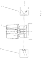
- the amount of oil entering the air stream in drops is scanned on the injector (13) by means of a light barrier consisting of transmitter (10) and receiver (11).
- the oil mist device (3) has a proportional behavior, ie the amount of oil discharged from the injector (13) in droplet form is proportional to the size of the air flow.
- the number of drops is registered with an electronic counter (14) and the count result is forwarded to the electronic logic unit (15) in terms of time units.
- the number of drops related to the time unit is evaluated with predetermined numerical values for the minimum number of drops per time unit and the maximum number of drops per time unit in the logic unit (15), and output information can be generated therefrom.
- the self-limiting electrical heater (2) generates a temperature above or near the ambient temperature in the fluid or fluid mixture supply, thereby avoiding an undesirable change in viscosity.
- the self-limiting effect of the heater (2) is designed so that the fluid or fluid mixture cannot be burned if the lubricant level drops below the wetted surfaces of the radiator (3) due to the function.
- the process-related drop in the fluid or fluid mixture level (12) is monitored with a level switch (17), symbol (16) in FIG. 2.
- the response of the level switch (17) leads to an indication of this situation in the logic unit (15). It is possible that an evaluation of all operating conditions is interpreted in a logical dependency and a corresponding signal is given to the outside as conclusions.
- the basic operational readiness of the system is signaled by a pressure switch (18).
Landscapes
- Engineering & Computer Science (AREA)
- General Engineering & Computer Science (AREA)
- Mechanical Engineering (AREA)
- Chemical & Material Sciences (AREA)
- Combustion & Propulsion (AREA)
- Oil, Petroleum & Natural Gas (AREA)
- Nozzles (AREA)
- Lubricants (AREA)
- Coating Apparatus (AREA)
Claims (6)
- Dispositif pour l'aspersion de surfaces, de cavités et de leur contenu par des fluides ou des mélanges de fluides, où le fluide ou le mélange de fluides est conduit à l'emplacement à asperger au moyen d'un courant d'air, présentant un réservoir (1) avec un interrupteur de niveau (17) pour le fluide ou le mélange de fluides, un séparateur d'eau avec filtre (6), un régulateur de pression (4), une vanne d'arrêt (6), un lubrificateur à embruns d'huile (3) et un interrupteur à pression (16), caractérisé en ce que le lubrificateur à embruns d'huile (3) présente un rapport proportionnel entre l'air débité et le fluide ou le mélange de fluides ajouté, et qu'un chauffage électrique à auto-limitation est disposé dans le réservoir (1).
- Dispositif selon revendication 1, caractérisé en ce que le chauffage à auto-limitation est disposé dans la partie inférieure du réservoir (1), de telle sorte qu'une surface de chauffe aussi étendue quc possible est toujours aspergée par le fluide ou le mélange de fluides en cas de niveau décroissant du réservoir (1).
- Dispositif selon revendication 1 ou 2, caractérisé en ce quel'injection de fluide est saisie numériquement par une barrière photoélectrique sur le lubrificateur à embruns d'huile (3) à la formation de la goutte d'injection,le nombre de gouttes est rapporté à une base temporelle et traité comme grandeur de mesure variable en temps n = f (t),la grandeur de mesure n = f (t) est comparée à des valeurs maximales données dans une unité logiqueun signal d'évaluation étant formé en cas de dépassement des valeurs maximales ou minimales.
- Dispositif selon revendication 3, caractérisé en ce quela grandeur de mesure n = f (t) est comparée à des valeurs maximales et minimales données dans une unité logiqueun signal d'évaluation étant formé en cas de dépassement des valeurs maximales ou minimales.
- Dispositif selon revendication 3, caractérisé en ce quela grandeur de mesure n = f (t) est comparée à une valeur de consigne donnée dans une unité logiquele débit de fluide conduit étant corrigé en cas de variation par rapport à cette valeur de consigne.
- Dispositif selon revendication 5, caractérisé en ce que la buse d'injecteur est utilisée en tant que composant de réglage pour la correction du débit de fluide.
Applications Claiming Priority (2)
| Application Number | Priority Date | Filing Date | Title |
|---|---|---|---|
| DE19811734 | 1998-03-18 | ||
| DE19811734A DE19811734A1 (de) | 1998-03-18 | 1998-03-18 | Vorrichtung zur Versorgung von Schmierstellen mit fluidem Schmiermittel |
Publications (2)
| Publication Number | Publication Date |
|---|---|
| EP0943861A1 EP0943861A1 (fr) | 1999-09-22 |
| EP0943861B1 true EP0943861B1 (fr) | 2002-08-07 |
Family
ID=7861310
Family Applications (1)
| Application Number | Title | Priority Date | Filing Date |
|---|---|---|---|
| EP98123330A Expired - Lifetime EP0943861B1 (fr) | 1998-03-18 | 1998-12-08 | Dispositif pour réaliser le mouillage de surfaces ou de cavités avec un liquide ou un mélange de liquides |
Country Status (3)
| Country | Link |
|---|---|
| EP (1) | EP0943861B1 (fr) |
| AT (1) | ATE221972T1 (fr) |
| DE (2) | DE19811734A1 (fr) |
Families Citing this family (1)
| Publication number | Priority date | Publication date | Assignee | Title |
|---|---|---|---|---|
| DE10207435A1 (de) * | 2002-02-21 | 2003-09-04 | Vogel Willi Ag | Verfahren und Vorrichtung zur Erzeugung eines Aerosols |
Family Cites Families (9)
| Publication number | Priority date | Publication date | Assignee | Title |
|---|---|---|---|---|
| US3491855A (en) * | 1968-07-17 | 1970-01-27 | Houdaille Industries Inc | Oil mist lubricating system |
| US4131658A (en) * | 1975-07-17 | 1978-12-26 | Nippon Oil Company Limited | Method for atomizing oil and an apparatus therefor |
| US4284670A (en) * | 1976-08-06 | 1981-08-18 | Aluminum Company Of America | Method for applying lubricants onto metal working surfaces |
| US4637493A (en) * | 1981-04-17 | 1987-01-20 | Lubricating Systems Company Of Texas, Inc. | Mist generators |
| US4807721A (en) * | 1986-03-21 | 1989-02-28 | Shoketsu Kinzoku Kabushiki Kaisha | Air line lubricator |
| DE4000733A1 (de) * | 1990-01-12 | 1991-07-18 | Limon Fluhme & Co De | Verfahren und vorrichtung zur kontinuierlichen versorgung von schmierstellen mit schmieroel |
| DE4002846A1 (de) * | 1990-02-01 | 1991-08-08 | Limon Fluhme & Co De | Verfahren und vorrichtung zum schmieren von schmierstellen mit schmierstoff-minimalmengen |
| US5327998A (en) * | 1992-09-18 | 1994-07-12 | The United States Of America As Represented By The Secretary Of The Air Force | Lubrication by sublimation |
| GB2303197B (en) * | 1995-07-07 | 1999-04-28 | Imi Norgren Inc | Fluid metering device and compressed air lubricator including same |
-
1998
- 1998-03-18 DE DE19811734A patent/DE19811734A1/de not_active Withdrawn
- 1998-12-08 DE DE59805095T patent/DE59805095D1/de not_active Expired - Lifetime
- 1998-12-08 AT AT98123330T patent/ATE221972T1/de not_active IP Right Cessation
- 1998-12-08 EP EP98123330A patent/EP0943861B1/fr not_active Expired - Lifetime
Also Published As
| Publication number | Publication date |
|---|---|
| EP0943861A1 (fr) | 1999-09-22 |
| DE19811734A1 (de) | 1999-09-23 |
| DE59805095D1 (de) | 2002-09-12 |
| ATE221972T1 (de) | 2002-08-15 |
Similar Documents
| Publication | Publication Date | Title |
|---|---|---|
| EP0733232B1 (fr) | Dispositif de dosage de fluides et installation de distribution de boissons equipee d'un tel dispositif de dosage | |
| EP1248927B1 (fr) | Dispositif de pulverisation d'additifs | |
| DE4213270C2 (de) | Vorrichtung zur Bestimmung und Unterscheidung unterschiedlicher Kältemittel | |
| DE3818161A1 (de) | Verfahren und vorrichtung zum kontinuierlichen beladen mindestens einer fliessfaehigen reaktionskomponente mit gas fuer die herstellung eines schaumstoffbildenden, fliessfaehigen reaktionsgemisches | |
| DE69418983T2 (de) | Verfahren und Vorrichtung zur Abgabe von Gasmengen unter Druck | |
| DE19733715C1 (de) | Verfahren und Anlage zur Abgabe von Flüssigkeit aus einem mehrere Kammern enthaltenden Tankwagen | |
| DE3522452A1 (de) | Anordnung fuer narkose und/oder beatmung mit einer befeuchtungs- und/oder verdampfungskammer | |
| EP1123163B1 (fr) | Procede et dispositif permettant de doser et de melanger divers constituants | |
| DE102009060454B4 (de) | Vorrichtung zur Aerosolerzeugung | |
| EP0516897B1 (fr) | Dispositif de dosage de liquides | |
| DE69724431T2 (de) | Befüllvorrichtung | |
| EP0943861A1 (fr) | Dispositif pour réaliser le mouillage de surfaces ou de cavités avec un liquide ou un mélange de liquides | |
| EP0175082A2 (fr) | Agencement de circuit pour l'emplissage et le remplissage régulé d'un réservoir avec des liquides | |
| DE4241074C2 (de) | Schmierstoffspender mit Einrichtung zur dosierten Schmierstoffabgabe und Verfahren zum Betrieb eines solchen Schmierstoffspenders | |
| EP2366076B1 (fr) | Lubrificateur à air comprimé | |
| DE102017003021B3 (de) | Heißleimauftragesystem und - verfahren | |
| DE102019112964A1 (de) | Injektionseinrichtung zur Injektion eines flüssigen Odoriermittels in einen durch eine Gasleitung strömenden Gasstrom, deren Verwendung und Verfahren zu deren Herstellung | |
| DE2420050C3 (de) | Vorrichtung zum Zerstäuben von öl in einer Druckluftleitung | |
| DE102017121426A1 (de) | Verfahren zur Füllstandsermittlung | |
| EP1402977B1 (fr) | Dispositif de gaz protecteur pour des machines à couler sous pression | |
| EP0179189A2 (fr) | Procédé et dispositif pour doser et mélanger deux liquides | |
| WO2003070382A1 (fr) | Procede et dispositif pour produire un aerosol | |
| EP0892682A1 (fr) | Pulverisateur, en particulier pour un robot d'assemblage | |
| DE10015331A1 (de) | Vorrichtung zur Zuführung eines Brennstoffgemischs in eine Brennstoffzelle | |
| DE202011102405U1 (de) | Pneumatische Vorrichtung oder pneumatisches System mit einer Öler-Vorrichtung |
Legal Events
| Date | Code | Title | Description |
|---|---|---|---|
| PUAI | Public reference made under article 153(3) epc to a published international application that has entered the european phase |
Free format text: ORIGINAL CODE: 0009012 |
|
| AK | Designated contracting states |
Kind code of ref document: A1 Designated state(s): AT CH DE FR LI |
|
| AX | Request for extension of the european patent |
Free format text: AL;LT;LV;MK;RO;SI |
|
| 17P | Request for examination filed |
Effective date: 20000321 |
|
| AKX | Designation fees paid |
Free format text: AT CH DE FR LI |
|
| GRAG | Despatch of communication of intention to grant |
Free format text: ORIGINAL CODE: EPIDOS AGRA |
|
| GRAG | Despatch of communication of intention to grant |
Free format text: ORIGINAL CODE: EPIDOS AGRA |
|
| GRAH | Despatch of communication of intention to grant a patent |
Free format text: ORIGINAL CODE: EPIDOS IGRA |
|
| GRAH | Despatch of communication of intention to grant a patent |
Free format text: ORIGINAL CODE: EPIDOS IGRA |
|
| 17Q | First examination report despatched |
Effective date: 20020510 |
|
| GRAA | (expected) grant |
Free format text: ORIGINAL CODE: 0009210 |
|
| AK | Designated contracting states |
Kind code of ref document: B1 Designated state(s): AT CH DE FR LI |
|
| PG25 | Lapsed in a contracting state [announced via postgrant information from national office to epo] |
Ref country code: FR Free format text: LAPSE BECAUSE OF FAILURE TO SUBMIT A TRANSLATION OF THE DESCRIPTION OR TO PAY THE FEE WITHIN THE PRESCRIBED TIME-LIMIT Effective date: 20020807 |
|
| REF | Corresponds to: |
Ref document number: 221972 Country of ref document: AT Date of ref document: 20020815 Kind code of ref document: T |
|
| REG | Reference to a national code |
Ref country code: CH Ref legal event code: EP |
|
| REF | Corresponds to: |
Ref document number: 59805095 Country of ref document: DE Date of ref document: 20020912 |
|
| PG25 | Lapsed in a contracting state [announced via postgrant information from national office to epo] |
Ref country code: LI Free format text: LAPSE BECAUSE OF NON-PAYMENT OF DUE FEES Effective date: 20021231 Ref country code: CH Free format text: LAPSE BECAUSE OF NON-PAYMENT OF DUE FEES Effective date: 20021231 |
|
| PLBE | No opposition filed within time limit |
Free format text: ORIGINAL CODE: 0009261 |
|
| STAA | Information on the status of an ep patent application or granted ep patent |
Free format text: STATUS: NO OPPOSITION FILED WITHIN TIME LIMIT |
|
| 26N | No opposition filed |
Effective date: 20030508 |
|
| REG | Reference to a national code |
Ref country code: CH Ref legal event code: PL |
|
| PGFP | Annual fee paid to national office [announced via postgrant information from national office to epo] |
Ref country code: AT Payment date: 20040630 Year of fee payment: 6 |
|
| PG25 | Lapsed in a contracting state [announced via postgrant information from national office to epo] |
Ref country code: AT Free format text: LAPSE BECAUSE OF NON-PAYMENT OF DUE FEES Effective date: 20041208 |
|
| PGFP | Annual fee paid to national office [announced via postgrant information from national office to epo] |
Ref country code: DE Payment date: 20141028 Year of fee payment: 17 |
|
| REG | Reference to a national code |
Ref country code: DE Ref legal event code: R119 Ref document number: 59805095 Country of ref document: DE |
|
| PG25 | Lapsed in a contracting state [announced via postgrant information from national office to epo] |
Ref country code: DE Free format text: LAPSE BECAUSE OF NON-PAYMENT OF DUE FEES Effective date: 20160701 |