EP0943876A1 - Wärmetauscher oder Wärmepumpe mit Querstromlüfter - Google Patents
Wärmetauscher oder Wärmepumpe mit Querstromlüfter Download PDFInfo
- Publication number
- EP0943876A1 EP0943876A1 EP99400642A EP99400642A EP0943876A1 EP 0943876 A1 EP0943876 A1 EP 0943876A1 EP 99400642 A EP99400642 A EP 99400642A EP 99400642 A EP99400642 A EP 99400642A EP 0943876 A1 EP0943876 A1 EP 0943876A1
- Authority
- EP
- European Patent Office
- Prior art keywords
- fan
- air
- wheel
- heat pump
- heat
- Prior art date
- Legal status (The legal status is an assumption and is not a legal conclusion. Google has not performed a legal analysis and makes no representation as to the accuracy of the status listed.)
- Granted
Links
Images


Classifications
-
- F—MECHANICAL ENGINEERING; LIGHTING; HEATING; WEAPONS; BLASTING
- F24—HEATING; RANGES; VENTILATING
- F24F—AIR-CONDITIONING; AIR-HUMIDIFICATION; VENTILATION; USE OF AIR CURRENTS FOR SCREENING
- F24F1/00—Room units for air-conditioning, e.g. separate or self-contained units or units receiving primary air from a central station
- F24F1/0007—Indoor units, e.g. fan coil units
- F24F1/0083—Indoor units, e.g. fan coil units with dehumidification means
-
- F—MECHANICAL ENGINEERING; LIGHTING; HEATING; WEAPONS; BLASTING
- F24—HEATING; RANGES; VENTILATING
- F24F—AIR-CONDITIONING; AIR-HUMIDIFICATION; VENTILATION; USE OF AIR CURRENTS FOR SCREENING
- F24F1/00—Room units for air-conditioning, e.g. separate or self-contained units or units receiving primary air from a central station
- F24F1/0007—Indoor units, e.g. fan coil units
- F24F1/0018—Indoor units, e.g. fan coil units characterised by fans
- F24F1/0033—Indoor units, e.g. fan coil units characterised by fans having two or more fans
-
- F—MECHANICAL ENGINEERING; LIGHTING; HEATING; WEAPONS; BLASTING
- F04—POSITIVE - DISPLACEMENT MACHINES FOR LIQUIDS; PUMPS FOR LIQUIDS OR ELASTIC FLUIDS
- F04D—NON-POSITIVE-DISPLACEMENT PUMPS
- F04D17/00—Radial-flow pumps, e.g. centrifugal pumps; Helico-centrifugal pumps
- F04D17/02—Radial-flow pumps, e.g. centrifugal pumps; Helico-centrifugal pumps having non-centrifugal stages, e.g. centripetal
- F04D17/04—Radial-flow pumps, e.g. centrifugal pumps; Helico-centrifugal pumps having non-centrifugal stages, e.g. centripetal of transverse-flow type
-
- F—MECHANICAL ENGINEERING; LIGHTING; HEATING; WEAPONS; BLASTING
- F04—POSITIVE - DISPLACEMENT MACHINES FOR LIQUIDS; PUMPS FOR LIQUIDS OR ELASTIC FLUIDS
- F04D—NON-POSITIVE-DISPLACEMENT PUMPS
- F04D29/00—Details, component parts, or accessories
- F04D29/02—Selection of particular materials
- F04D29/023—Selection of particular materials especially adapted for elastic fluid pumps
-
- F—MECHANICAL ENGINEERING; LIGHTING; HEATING; WEAPONS; BLASTING
- F04—POSITIVE - DISPLACEMENT MACHINES FOR LIQUIDS; PUMPS FOR LIQUIDS OR ELASTIC FLUIDS
- F04D—NON-POSITIVE-DISPLACEMENT PUMPS
- F04D29/00—Details, component parts, or accessories
- F04D29/26—Rotors specially for elastic fluids
- F04D29/28—Rotors specially for elastic fluids for centrifugal or helico-centrifugal pumps for radial-flow or helico-centrifugal pumps
- F04D29/281—Rotors specially for elastic fluids for centrifugal or helico-centrifugal pumps for radial-flow or helico-centrifugal pumps for fans or blowers
- F04D29/282—Rotors specially for elastic fluids for centrifugal or helico-centrifugal pumps for radial-flow or helico-centrifugal pumps for fans or blowers the leading edge of each vane being substantially parallel to the rotation axis
- F04D29/283—Rotors specially for elastic fluids for centrifugal or helico-centrifugal pumps for radial-flow or helico-centrifugal pumps for fans or blowers the leading edge of each vane being substantially parallel to the rotation axis rotors of the squirrel-cage type
-
- F—MECHANICAL ENGINEERING; LIGHTING; HEATING; WEAPONS; BLASTING
- F04—POSITIVE - DISPLACEMENT MACHINES FOR LIQUIDS; PUMPS FOR LIQUIDS OR ELASTIC FLUIDS
- F04D—NON-POSITIVE-DISPLACEMENT PUMPS
- F04D29/00—Details, component parts, or accessories
- F04D29/40—Casings; Connections of working fluid
- F04D29/42—Casings; Connections of working fluid for radial or helico-centrifugal pumps
- F04D29/4206—Casings; Connections of working fluid for radial or helico-centrifugal pumps especially adapted for elastic fluid pumps
- F04D29/422—Discharge tongues
-
- F—MECHANICAL ENGINEERING; LIGHTING; HEATING; WEAPONS; BLASTING
- F24—HEATING; RANGES; VENTILATING
- F24F—AIR-CONDITIONING; AIR-HUMIDIFICATION; VENTILATION; USE OF AIR CURRENTS FOR SCREENING
- F24F1/00—Room units for air-conditioning, e.g. separate or self-contained units or units receiving primary air from a central station
- F24F1/0007—Indoor units, e.g. fan coil units
- F24F1/0011—Indoor units, e.g. fan coil units characterised by air outlets
- F24F1/0014—Indoor units, e.g. fan coil units characterised by air outlets having two or more outlet openings
-
- F—MECHANICAL ENGINEERING; LIGHTING; HEATING; WEAPONS; BLASTING
- F24—HEATING; RANGES; VENTILATING
- F24F—AIR-CONDITIONING; AIR-HUMIDIFICATION; VENTILATION; USE OF AIR CURRENTS FOR SCREENING
- F24F1/00—Room units for air-conditioning, e.g. separate or self-contained units or units receiving primary air from a central station
- F24F1/0007—Indoor units, e.g. fan coil units
- F24F1/0018—Indoor units, e.g. fan coil units characterised by fans
- F24F1/0025—Cross-flow or tangential fans
-
- F—MECHANICAL ENGINEERING; LIGHTING; HEATING; WEAPONS; BLASTING
- F24—HEATING; RANGES; VENTILATING
- F24F—AIR-CONDITIONING; AIR-HUMIDIFICATION; VENTILATION; USE OF AIR CURRENTS FOR SCREENING
- F24F1/00—Room units for air-conditioning, e.g. separate or self-contained units or units receiving primary air from a central station
- F24F1/0007—Indoor units, e.g. fan coil units
- F24F1/0043—Indoor units, e.g. fan coil units characterised by mounting arrangements
- F24F1/0057—Indoor units, e.g. fan coil units characterised by mounting arrangements mounted in or on a wall
-
- F—MECHANICAL ENGINEERING; LIGHTING; HEATING; WEAPONS; BLASTING
- F24—HEATING; RANGES; VENTILATING
- F24F—AIR-CONDITIONING; AIR-HUMIDIFICATION; VENTILATION; USE OF AIR CURRENTS FOR SCREENING
- F24F1/00—Room units for air-conditioning, e.g. separate or self-contained units or units receiving primary air from a central station
- F24F1/0007—Indoor units, e.g. fan coil units
- F24F1/0059—Indoor units, e.g. fan coil units characterised by heat exchangers
- F24F1/0063—Indoor units, e.g. fan coil units characterised by heat exchangers by the mounting or arrangement of the heat exchangers
-
- F—MECHANICAL ENGINEERING; LIGHTING; HEATING; WEAPONS; BLASTING
- F24—HEATING; RANGES; VENTILATING
- F24F—AIR-CONDITIONING; AIR-HUMIDIFICATION; VENTILATION; USE OF AIR CURRENTS FOR SCREENING
- F24F1/00—Room units for air-conditioning, e.g. separate or self-contained units or units receiving primary air from a central station
- F24F1/0007—Indoor units, e.g. fan coil units
- F24F1/0059—Indoor units, e.g. fan coil units characterised by heat exchangers
- F24F1/0067—Indoor units, e.g. fan coil units characterised by heat exchangers by the shape of the heat exchangers or of parts thereof, e.g. of their fins
-
- F—MECHANICAL ENGINEERING; LIGHTING; HEATING; WEAPONS; BLASTING
- F24—HEATING; RANGES; VENTILATING
- F24F—AIR-CONDITIONING; AIR-HUMIDIFICATION; VENTILATION; USE OF AIR CURRENTS FOR SCREENING
- F24F1/00—Room units for air-conditioning, e.g. separate or self-contained units or units receiving primary air from a central station
- F24F1/0007—Indoor units, e.g. fan coil units
- F24F1/0071—Indoor units, e.g. fan coil units with means for purifying supplied air
-
- F—MECHANICAL ENGINEERING; LIGHTING; HEATING; WEAPONS; BLASTING
- F05—INDEXING SCHEMES RELATING TO ENGINES OR PUMPS IN VARIOUS SUBCLASSES OF CLASSES F01-F04
- F05D—INDEXING SCHEME FOR ASPECTS RELATING TO NON-POSITIVE-DISPLACEMENT MACHINES OR ENGINES, GAS-TURBINES OR JET-PROPULSION PLANTS
- F05D2300/00—Materials; Properties thereof
- F05D2300/50—Intrinsic material properties or characteristics
- F05D2300/514—Porosity
Definitions
- This invention relates to a machine for heating or cooling the atmosphere, such than a hot or cold transmitter or a heat pump heat including a tangential fan.
- Tangential fans include a bladed wheel which draws ambient gas into a direction perpendicular to its axis of rotation and the returns in another direction perpendicular to this axis. They have the advantage of offering a high flow for a small footprint, but their job in home applications is problematic because of their noise, normally too high to meet current standards on devices discussed here. This is why common air conditioners include fans helical (flow in the axis of rotation of the impeller) or centrifugal (with flat ejection flow and radiating over a full circle). These two kinds of fans, however, require large areas of air flow, and therefore a large area of device. The object of the invention was to rehabilitate tangential fans for uses domestic thanks to a particular construction which makes them quieter.
- Lacrosse beak porous has already been proposed in US-3 patent 695,775 A, but this is considered to be insufficient for the application envisaged here, where the requirements are strict.
- the fan does not have a nozzle scroll at the entrance, and the fan wheel is fitted with blades with pitch angle greater than 50 °.
- Other provisions, particularly favorable for improve flow, have been adopted in the emitter as the heat pump and are offered at accessory title.
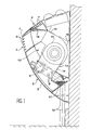
- a transmitter according to the invention is attached to a wall and its envelope has a triangle-shaped section irregular whose longest rear side is side of the wall, the top side, tilted slightly towards the bottom from the wall, is the shortest and the side lower, oblique, connects to the previous one by a tip 1.
- the lower side has an opening air inlet 2 veiled by a filter grid 3 and, above this entry 2 but just below tip 1, a first air outlet 4; a second air outlet 5 is arranged across the side top of the envelope, a little above the tip 1.
- These air outlets 4 and 5 are furnished with fins 6 and 7, directed downwards and outwards for the first exit 4 and up and out for the second outlet 5.
- a heat exchanger 8 is arranged in the envelope, behind the grid 3; he consists of a network of tubes 9 of circular section which lead to two conduits 10 assigned to the supply and return of a liquid, refrigerant or circulating as the case may be.
- the conduits 10 extend on one side of the envelope and out of it before join an appropriate facility that is part of the building in which the transmitter is installed.
- a tray 11 is located under the tubes 9 for if necessary collect the humidity of the air which has condensed on them.
- a purge duct which can be open at will and not shown, allows you to empty it.
- the centerpiece of the aircraft is a tangential fan 12 placed in an envelope 13 internal to the outer sectional enclosure triangular.
- This internal envelope 13 includes a entrance pavilion 14 ending in front of the heat 8, an outlet volute 15 ending in front of the air outlets 4 and 5 (which converge) and a chamber 16 intermediate to the previous ones and which houses the wheel 17 of the fan 12.
- a flap 18 is articulated to the outer envelope of the transmitter and oscillates between two extreme positions where it closes one or other of the air outlets 4 and 5 while by directing the air leaving volute 15, up to which it extends towards the other air outlets 4 and 5.
- FIG. 3 shows in more detail the fan 12. Aerodynamic studies show that the air is blown out locally by taking a vortex aspect in the extent of a vortex V. This vortex V would be located in the center of wheel 17 if it was in the center of a circular chamber but the resulting flow would then be zero. So that the fan 12 is working, chamber 16 is therefore asymmetrical, and the internal envelope 13 present at particular an inward projection, which is called traditionally a butt stock 19 and which extends almost to wheel 17 where it runs towards the entrance pavilion 14: the air that accompanies the wheel 17 around it is stopped and disperses either towards exit 15, i.e.
- the mouthpiece butt 19 is porous.
- the beak of butt 19 is a piece of perforated sheet metal whose pores occupy 32% of the surface.
- a return current towards the entrance pavilion 14 is therefore tolerated through pores, but the air flow supplied by the fan 12 is still sufficient, and it is moreover possible to extend the butt end 19 compared to previous solutions for it to come closer to wheel 17 (at ten millimeters per example); we also have it more downstream than it is not usual, in order to increase the flow.
- blades 23 of the wheel 17 A good design, that of a prototype built, anticipates that they are at number thirty and range between diameters of 60 mm and 49.44 mm from the wheel 17; their rope C (distance taken on a straight line between their ends) is 6.3 mm, their camber angle ⁇ of 72.55 ° and their setting angle ⁇ (between chord C and tangent wheel 17 taken at the inside diameter) is 53.18 °.
- the flow is even easier if the volute 15 folds back towards the entrance pavilion 14, and more precisely if the lower surface 24 and 25 of the internal envelope 13 forms an angle ⁇ acute on either side of the butt end 19: this angle is obtuse in existing fans. This particularity is only exploited here when part 18 directs the flow to the first air outlet 4, whose lower surface 25 delimits the duct.
- An auxiliary provision consists of place the blades 23 in a spin along the wheel 12, to prevent them from passing periodically in front butt 19, which would produce beats and sound peaks at these frequencies.
- Such a pale 23 twisted is illustrated in Figure 2.
- a characteristic of tangential fans 12 is to raise the air pressure more strongly than other kinds of fans, so 8 thicker heat exchangers or longer tubes tight, and therefore more temperature variations large for the air passing through the device, are possible.
- Such a device extracts heat from a cold source and brings it to a hot spring through a fluid traversing a closed circuit which makes it pass alternately by two heat exchangers located at thermal sources, and in which, in general, vaporizes and condenses respectively; a compressor and a regulator are placed respectively on the two branches of the circuit which connect the exchangers.
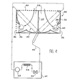
- a another aspect of the invention does not, however, relate to the organization of a heat pump but on the provision of ventilation means which facilitate air circulation in the room to be heated or cool through the heat exchanger correspondent: these means can be placed from the as shown in figure 4, in a fan unit 30 seen from above and comprising a section wall 31 rectangular enclosing two compartments 32 housing each a heat exchanger 33, diagonally in the compartment, and a fan 34 in a corner of the compartment; exchangers 33 form an open vee towards a suction face 35, screened, from the block fan 30 and the fans 34 are still arranged at two corners of the fan unit 30: the air flow enters block 30 from the face suction 35 in a uniform flow before fork towards the fans 34 by crossing the exchangers 33 by their smallest dimension; he leaves fan block 30 through openings mesh 36 which occupies part of its faces lateral; a partition 37 separating the compartments 32 ensures the symmetry of the flow.
- the fans 34 are analogous to the fans 12 of the previous embodiment and include in particular a porous butt end 38, analogous to the butt end 19 already encountered. All other improvements concerning the wheel, its arrangement in fan casing and shape of this envelope can be adopted or not. However, the requirements for acoustic discretion may be smaller for heat pumps, which have always been noisy.
- the fan unit 30 is isolated from the rest of the pump, which belongs to a compressor block 41 placed in another room, not devoted to the house, so that we don't have to hear its noise, which comes mainly from a compressor 42 attached to a motor not shown; the compressor block 41 also includes a heat exchanger 43 communicating with the cold source (if the room in which is the fan block 30 should be heated) and a regulator 44. All of these are interconnected by a circuit of conduits 45 which also passes through exchangers 33, where it branches off.
Landscapes
- Engineering & Computer Science (AREA)
- Mechanical Engineering (AREA)
- General Engineering & Computer Science (AREA)
- Chemical & Material Sciences (AREA)
- Combustion & Propulsion (AREA)
- Physics & Mathematics (AREA)
- Thermal Sciences (AREA)
- Structures Of Non-Positive Displacement Pumps (AREA)
- Domestic Hot-Water Supply Systems And Details Of Heating Systems (AREA)
- Thermotherapy And Cooling Therapy Devices (AREA)
- Heat-Exchange Devices With Radiators And Conduit Assemblies (AREA)
- Applications Or Details Of Rotary Compressors (AREA)
Applications Claiming Priority (2)
| Application Number | Priority Date | Filing Date | Title |
|---|---|---|---|
| FR9803369A FR2776369B1 (fr) | 1998-03-19 | 1998-03-19 | Emetteur de chaud ou de froid ou pompe a chaleur a ventilateur tangentiel |
| FR9803369 | 1998-03-19 |
Publications (2)
| Publication Number | Publication Date |
|---|---|
| EP0943876A1 true EP0943876A1 (de) | 1999-09-22 |
| EP0943876B1 EP0943876B1 (de) | 2003-05-28 |
Family
ID=9524224
Family Applications (1)
| Application Number | Title | Priority Date | Filing Date |
|---|---|---|---|
| EP99400642A Expired - Lifetime EP0943876B1 (de) | 1998-03-19 | 1999-03-16 | Wärmetauscher oder Wärmepumpe mit Querstromlüfter |
Country Status (4)
| Country | Link |
|---|---|
| EP (1) | EP0943876B1 (de) |
| AT (1) | ATE241784T1 (de) |
| DE (1) | DE69908225D1 (de) |
| FR (1) | FR2776369B1 (de) |
Cited By (2)
| Publication number | Priority date | Publication date | Assignee | Title |
|---|---|---|---|---|
| EP2019950A4 (de) * | 2006-05-20 | 2012-02-29 | Lg Electronics Inc | Klimaanlage |
| CN114811733A (zh) * | 2022-04-15 | 2022-07-29 | 青岛海尔空调器有限总公司 | 空调室内机及空调器 |
Families Citing this family (1)
| Publication number | Priority date | Publication date | Assignee | Title |
|---|---|---|---|---|
| CN106152280A (zh) * | 2016-08-01 | 2016-11-23 | 珠海格力电器股份有限公司 | 空调装置 |
Citations (5)
| Publication number | Priority date | Publication date | Assignee | Title |
|---|---|---|---|---|
| GB1102092A (en) * | 1964-02-05 | 1968-02-07 | Firth Cleveland Ltd | Improvements relating to machines of the cross-flow type for inducing flow of fluid |
| US3646875A (en) * | 1969-08-14 | 1972-03-07 | Kurt Zenkner | Device for adjusting the temperature |
| US3695775A (en) * | 1969-10-10 | 1972-10-03 | Kurt Dr Ing Zenkner | Cross flow blower |
| US4733542A (en) * | 1986-12-05 | 1988-03-29 | Enviromaster International Corporation | Cabinet for air conditioning system |
| EP0816687A2 (de) * | 1996-06-28 | 1998-01-07 | Kabushiki Kaisha Toshiba | Querstromlüfterrad, Giessform für Lüfterrad, und Herstellungsverfahren für diese Giessform |
-
1998
- 1998-03-19 FR FR9803369A patent/FR2776369B1/fr not_active Expired - Fee Related
-
1999
- 1999-03-16 DE DE69908225T patent/DE69908225D1/de not_active Expired - Lifetime
- 1999-03-16 EP EP99400642A patent/EP0943876B1/de not_active Expired - Lifetime
- 1999-03-16 AT AT99400642T patent/ATE241784T1/de not_active IP Right Cessation
Patent Citations (5)
| Publication number | Priority date | Publication date | Assignee | Title |
|---|---|---|---|---|
| GB1102092A (en) * | 1964-02-05 | 1968-02-07 | Firth Cleveland Ltd | Improvements relating to machines of the cross-flow type for inducing flow of fluid |
| US3646875A (en) * | 1969-08-14 | 1972-03-07 | Kurt Zenkner | Device for adjusting the temperature |
| US3695775A (en) * | 1969-10-10 | 1972-10-03 | Kurt Dr Ing Zenkner | Cross flow blower |
| US4733542A (en) * | 1986-12-05 | 1988-03-29 | Enviromaster International Corporation | Cabinet for air conditioning system |
| EP0816687A2 (de) * | 1996-06-28 | 1998-01-07 | Kabushiki Kaisha Toshiba | Querstromlüfterrad, Giessform für Lüfterrad, und Herstellungsverfahren für diese Giessform |
Cited By (2)
| Publication number | Priority date | Publication date | Assignee | Title |
|---|---|---|---|---|
| EP2019950A4 (de) * | 2006-05-20 | 2012-02-29 | Lg Electronics Inc | Klimaanlage |
| CN114811733A (zh) * | 2022-04-15 | 2022-07-29 | 青岛海尔空调器有限总公司 | 空调室内机及空调器 |
Also Published As
| Publication number | Publication date |
|---|---|
| EP0943876B1 (de) | 2003-05-28 |
| FR2776369A1 (fr) | 1999-09-24 |
| FR2776369B1 (fr) | 2000-05-05 |
| DE69908225D1 (de) | 2003-07-03 |
| ATE241784T1 (de) | 2003-06-15 |
Similar Documents
| Publication | Publication Date | Title |
|---|---|---|
| FR2886380A1 (fr) | Echangeur thermique total et un systeme de ventilation utilisant le meme | |
| FR2687189A1 (fr) | Ventilateur a air de refroidissement, pour moteurs thermiques, equipe d'un conduit d'air comburant deviant un courant d'air partiel. | |
| WO2018203366A1 (ja) | 電動送風機、電気掃除機、およびハンドドライヤー | |
| EP0017517A2 (de) | Leitvorrichtung zur Mischung trockener und nasser paralleler Kühlluftströme | |
| FR2766882A1 (fr) | Ventilateur centrifuge a conduit perfectionne de refroidissement du moteur, notamment pour vehicule automobile | |
| FR2465908A1 (de) | ||
| EP0943876B1 (de) | Wärmetauscher oder Wärmepumpe mit Querstromlüfter | |
| FR2867263A1 (fr) | Installation de sechage pour une bande defilante, notamment pour une bande de papier | |
| FR2838378A1 (fr) | Systeme de climatisation pour vehicule | |
| FR2779510A1 (fr) | Porte froide de four de cuisson | |
| FR2614090A3 (fr) | Appareil mobile de climatisation de locaux | |
| EP3853057A1 (de) | Wärmetauschermodul, insbesondere für ein kraftfahrzeug | |
| JP3807184B2 (ja) | 除湿機 | |
| CN220757364U (zh) | 一种湿气进气结构以及水汽分离装置 | |
| FR3074236A1 (fr) | Groupe moto-ventilateur pour vehicule automobile | |
| CN109405027B (zh) | 薄型烟机 | |
| EP3976408A1 (de) | Kühlmodul für ein elektrofahrzeug mit einer strömungsmaschine | |
| FR2726891A1 (fr) | Appareil soufflant a batterie ailetee pour le conditionnement de l'air dans les locaux | |
| BE832814A (fr) | Perfectionnements aux soufflantes peripheriques | |
| BE518780A (de) | ||
| FR2587457A3 (fr) | Conditionneur d'air de type monobloc a systeme de ventilation a faible bruit | |
| FR2951816A1 (fr) | Secheur industriel a pompe a chaleur. | |
| FR3146982A1 (fr) | Unité intérieure d’un appareil de climatisation | |
| CN109595649A (zh) | 一种近吸式吸油烟机 | |
| FR2833339A1 (fr) | Dispositif de traitement d'air |
Legal Events
| Date | Code | Title | Description |
|---|---|---|---|
| PUAI | Public reference made under article 153(3) epc to a published international application that has entered the european phase |
Free format text: ORIGINAL CODE: 0009012 |
|
| AK | Designated contracting states |
Kind code of ref document: A1 Designated state(s): AT BE CH DE ES FR GB GR IT LI NL PT |
|
| AX | Request for extension of the european patent |
Free format text: AL;LT;LV;MK;RO;SI |
|
| 17P | Request for examination filed |
Effective date: 20000302 |
|
| AKX | Designation fees paid |
Free format text: AT BE CH DE ES FR GB GR IT LI NL PT |
|
| GRAH | Despatch of communication of intention to grant a patent |
Free format text: ORIGINAL CODE: EPIDOS IGRA |
|
| GRAH | Despatch of communication of intention to grant a patent |
Free format text: ORIGINAL CODE: EPIDOS IGRA |
|
| GRAA | (expected) grant |
Free format text: ORIGINAL CODE: 0009210 |
|
| AK | Designated contracting states |
Designated state(s): AT BE CH DE ES FR GB GR IT LI NL PT |
|
| PG25 | Lapsed in a contracting state [announced via postgrant information from national office to epo] |
Ref country code: NL Free format text: LAPSE BECAUSE OF FAILURE TO SUBMIT A TRANSLATION OF THE DESCRIPTION OR TO PAY THE FEE WITHIN THE PRESCRIBED TIME-LIMIT Effective date: 20030528 Ref country code: IT Free format text: LAPSE BECAUSE OF FAILURE TO SUBMIT A TRANSLATION OF THE DESCRIPTION OR TO PAY THE FEE WITHIN THE PRESCRIBED TIME-LIMIT;WARNING: LAPSES OF ITALIAN PATENTS WITH EFFECTIVE DATE BEFORE 2007 MAY HAVE OCCURRED AT ANY TIME BEFORE 2007. THE CORRECT EFFECTIVE DATE MAY BE DIFFERENT FROM THE ONE RECORDED. Effective date: 20030528 Ref country code: GB Free format text: LAPSE BECAUSE OF FAILURE TO SUBMIT A TRANSLATION OF THE DESCRIPTION OR TO PAY THE FEE WITHIN THE PRESCRIBED TIME-LIMIT Effective date: 20030528 Ref country code: AT Free format text: LAPSE BECAUSE OF FAILURE TO SUBMIT A TRANSLATION OF THE DESCRIPTION OR TO PAY THE FEE WITHIN THE PRESCRIBED TIME-LIMIT Effective date: 20030528 |
|
| REG | Reference to a national code |
Ref country code: GB Ref legal event code: FG4D Free format text: NOT ENGLISH |
|
| REG | Reference to a national code |
Ref country code: CH Ref legal event code: EP |
|
| REF | Corresponds to: |
Ref document number: 69908225 Country of ref document: DE Date of ref document: 20030703 Kind code of ref document: P |
|
| PG25 | Lapsed in a contracting state [announced via postgrant information from national office to epo] |
Ref country code: PT Free format text: LAPSE BECAUSE OF FAILURE TO SUBMIT A TRANSLATION OF THE DESCRIPTION OR TO PAY THE FEE WITHIN THE PRESCRIBED TIME-LIMIT Effective date: 20030828 Ref country code: GR Free format text: LAPSE BECAUSE OF FAILURE TO SUBMIT A TRANSLATION OF THE DESCRIPTION OR TO PAY THE FEE WITHIN THE PRESCRIBED TIME-LIMIT Effective date: 20030828 |
|
| PG25 | Lapsed in a contracting state [announced via postgrant information from national office to epo] |
Ref country code: DE Free format text: LAPSE BECAUSE OF FAILURE TO SUBMIT A TRANSLATION OF THE DESCRIPTION OR TO PAY THE FEE WITHIN THE PRESCRIBED TIME-LIMIT Effective date: 20030829 |
|
| PG25 | Lapsed in a contracting state [announced via postgrant information from national office to epo] |
Ref country code: ES Free format text: LAPSE BECAUSE OF FAILURE TO SUBMIT A TRANSLATION OF THE DESCRIPTION OR TO PAY THE FEE WITHIN THE PRESCRIBED TIME-LIMIT Effective date: 20030908 |
|
| NLV1 | Nl: lapsed or annulled due to failure to fulfill the requirements of art. 29p and 29m of the patents act | ||
| GBV | Gb: ep patent (uk) treated as always having been void in accordance with gb section 77(7)/1977 [no translation filed] |
Effective date: 20030528 |
|
| PG25 | Lapsed in a contracting state [announced via postgrant information from national office to epo] |
Ref country code: LI Free format text: LAPSE BECAUSE OF NON-PAYMENT OF DUE FEES Effective date: 20040331 Ref country code: CH Free format text: LAPSE BECAUSE OF NON-PAYMENT OF DUE FEES Effective date: 20040331 Ref country code: BE Free format text: LAPSE BECAUSE OF NON-PAYMENT OF DUE FEES Effective date: 20040331 |
|
| PLBE | No opposition filed within time limit |
Free format text: ORIGINAL CODE: 0009261 |
|
| STAA | Information on the status of an ep patent application or granted ep patent |
Free format text: STATUS: NO OPPOSITION FILED WITHIN TIME LIMIT |
|
| 26N | No opposition filed |
Effective date: 20040302 |
|
| BERE | Be: lapsed |
Owner name: *ELECTRICITE DE FRANCE Effective date: 20040331 |
|
| REG | Reference to a national code |
Ref country code: CH Ref legal event code: PL |
|
| PG25 | Lapsed in a contracting state [announced via postgrant information from national office to epo] |
Ref country code: FR Free format text: LAPSE BECAUSE OF NON-PAYMENT OF DUE FEES Effective date: 20041130 |
|
| REG | Reference to a national code |
Ref country code: FR Ref legal event code: ST |