EP0943884A1 - Wärmetauscher - Google Patents
Wärmetauscher Download PDFInfo
- Publication number
- EP0943884A1 EP0943884A1 EP97946121A EP97946121A EP0943884A1 EP 0943884 A1 EP0943884 A1 EP 0943884A1 EP 97946121 A EP97946121 A EP 97946121A EP 97946121 A EP97946121 A EP 97946121A EP 0943884 A1 EP0943884 A1 EP 0943884A1
- Authority
- EP
- European Patent Office
- Prior art keywords
- plate
- header
- partition
- members
- channel
- Prior art date
- Legal status (The legal status is an assumption and is not a legal conclusion. Google has not performed a legal analysis and makes no representation as to the accuracy of the status listed.)
- Granted
Links
Images


Classifications
-
- F—MECHANICAL ENGINEERING; LIGHTING; HEATING; WEAPONS; BLASTING
- F28—HEAT EXCHANGE IN GENERAL
- F28F—DETAILS OF HEAT-EXCHANGE AND HEAT-TRANSFER APPARATUS, OF GENERAL APPLICATION
- F28F9/00—Casings; Header boxes; Auxiliary supports for elements; Auxiliary members within casings
- F28F9/02—Header boxes; End plates
- F28F9/0219—Arrangements for sealing end plates into casing or header box; Header box sub-elements
- F28F9/0221—Header boxes or end plates formed by stacked elements
-
- F—MECHANICAL ENGINEERING; LIGHTING; HEATING; WEAPONS; BLASTING
- F28—HEAT EXCHANGE IN GENERAL
- F28D—HEAT-EXCHANGE APPARATUS, NOT PROVIDED FOR IN ANOTHER SUBCLASS, IN WHICH THE HEAT-EXCHANGE MEDIA DO NOT COME INTO DIRECT CONTACT
- F28D1/00—Heat-exchange apparatus having stationary conduit assemblies for one heat-exchange medium only, the media being in contact with different sides of the conduit wall, in which the other heat-exchange medium is a large body of fluid, e.g. domestic or motor car radiators
- F28D1/02—Heat-exchange apparatus having stationary conduit assemblies for one heat-exchange medium only, the media being in contact with different sides of the conduit wall, in which the other heat-exchange medium is a large body of fluid, e.g. domestic or motor car radiators with heat-exchange conduits immersed in the body of fluid
- F28D1/03—Heat-exchange apparatus having stationary conduit assemblies for one heat-exchange medium only, the media being in contact with different sides of the conduit wall, in which the other heat-exchange medium is a large body of fluid, e.g. domestic or motor car radiators with heat-exchange conduits immersed in the body of fluid with plate-like or laminated conduits
- F28D1/0366—Heat-exchange apparatus having stationary conduit assemblies for one heat-exchange medium only, the media being in contact with different sides of the conduit wall, in which the other heat-exchange medium is a large body of fluid, e.g. domestic or motor car radiators with heat-exchange conduits immersed in the body of fluid with plate-like or laminated conduits the conduits being formed by spaced plates with inserted elements
- F28D1/0375—Heat-exchange apparatus having stationary conduit assemblies for one heat-exchange medium only, the media being in contact with different sides of the conduit wall, in which the other heat-exchange medium is a large body of fluid, e.g. domestic or motor car radiators with heat-exchange conduits immersed in the body of fluid with plate-like or laminated conduits the conduits being formed by spaced plates with inserted elements the plates having lateral openings therein for circulation of the heat-exchange medium from one conduit to another
Definitions
- the present invention relates to heat exchangers, for example, for use as air-cooled oil coolers, after coolers, inter coolers, radiators, etc.
- Plate fin heat exchangers of the so-called drawn cup type which can be manufactured with a high efficiency are generally used as heat exchangers for use as air-cooled oil coolers or air-cooled after coolers for various industrial devices.
- the heat exchangers of this type comprise fluid channel members and fins which are arranged alternately in layers, the channel members being each composed of a pair of dishlike plates which are joined as opposed to each other.
- Each of the plates has at each of its opposite ends a header recessed portion which is shaped in the form of a cup by drawing and formed with a fluid passing hole in its bottom wall. The holes thus formed in the fluid channel members provide a header at each end of the heat exchanger.
- the plates are shaped by press work using a single kind of die, so that there arises a need to prepare another die anew when the length of the core portions, i.e., the length of the plates, is to be changed.
- the length of the core portions i.e., the length of the plates
- the cup-shaped header recessed portions of the plates have a reduced thickness smaller than the plate thickness owing to the drawing work, with the result that the headers become insufficient in pressure resistance, vibration resistance and corrosion resistance.
- Conventional heat exchangers include those which comprise fluid channel members each formed by joining a pair of dishlike plates, or a dishlike plate and a flat plate, and annular header members each interposed between the corresponding ends of each pair of adjacent fluid channel members.
- the header members are superior to the header recessed portions of the plate fin heat exchanger of the drawn cup type in resistance to pressure, vibration and corrosion, whereas since the dishlike plates are similarly shaped by press work using a single kind of die, there arises a need to prepare another die anew when the length of the core portions, i.e., the length of the plates, is to be changed.
- Heat exchangers are also available conventionally which comprise fluid channel members each composed of an intermediate plate having a channel forming slit and flat outer plates joined respectively to opposite sides of the intermediate plate, and annular header members each interposed between the corresponding ends of each pair of adjacent fluid channel members.
- the heat exchangers of this type are inferior to plate fin heat exchangers of the drawn cup type in productivity, while there is a need to prepare another die anew when the length of the intermediate plates is to be changed. Additionally, if it is attempted to form a piping socket communication bore across two adjacent header members, for example, for connection to piping of increased diameter, the fluid channel member comprising three plates and having a relatively large thickness will offer resistance to the flow of fluid through the socket communication bore. It is therefore impossible to form the piping socket communication bore, consequently limiting the freedom to position the piping connection correspondingly.
- An object of the present invention is to provide a heat exchanger which readily permits changes in the length of its core portions as demanded although comparable to plate fin heat exchangers of the drawn cup type in productivity and which comprises headers having high resistance to pressure, vibration and corrosion and is less likely to be limited in the freedom to position the piping connection.
- the present invention provides a heat exchanger comprising a plurality of fluid channel members arranged one above another in parallel at a spacing and each composed of a pair of plates, each of the plates having a fluid passing hole at each of opposite lateral ends thereof and a channel portion extending over the entire length thereof between the end holes for forming a fluid channel, the pair of plates being joined with recessed surfaces of their channel portions opposed to each other to form the fluid channel member; and annular header members each interposed between each pair of adjacent fluid channel members at each of opposite lateral ends of the heat exchanger, each of the header members having upper and lower end faces each comprising a flat portion to be fitted to a flat portion of an edge of each plate defining the end hole thereof and a recessed portion to be fitted to a protuberant end face of the plate channel portion, the upper and lower end faces of each of the header members at each of the opposite lateral ends of the exchanger being joined to a peripheral edge portion of the plate immediately adjacent thereto and defining an opening formed by the end hole of the plate and an open end of
- the plates and the header members are joined into an exchanger body, for example, by collective vacuum brazing, so that the heat exchanger is comparable to plate fin heat exchangers of the drawn cup type in productivity.
- the plates of the heat exchanger each have a fluid passing hole at each of opposite lateral ends thereof and a channel portion extending over the entire length thereof between the end holes for forming a fluid channel, so that the length of the plates can be altered with extreme ease as demanded.
- the heat exchanger is therefore suited especially for use as heat exchangers for industrial devices which exchangers are to be fabricated in many kinds in a small quantity for each kind.
- the annular header members for forming the header can be obtained, for example, by cutting a hollow extrudate having a relatively large thickness into blocks of predetermined size and forming a recessed portion partly in the cut end faces of the cut blocks.
- the header members are therefore easy to make and excellent in resistance to pressure, vibration and corrosion.
- the material for the plates is a double-faced aluminum brazing sheet in view of bondability, whereas other metal may alternatively be used.
- the annular header members can be obtained by cutting a hollow extrudate, for example, of aluminum (including an aluminum alloy, the same as hereinafter) having a relatively large thickness into blocks of predetermined size and forming a recessed portion partly in the cut end faces of the cut blocks.
- the header members are therefore easy to make and excellent in resistance to pressure, vibration and corrosion.
- An outer fin which is usually a corrugated fin, is interposed between each pair of adjacent fluid channel members of the heat exchanger.
- An inner fin such as an offset fin or corrugated fin of the straight type, may further be inserted in the fluid channel of the fluid channel member.
- Side plates are disposed externally of the respective fluid channel members at opposite ends of the arrangement of channel members in layers with respect to the direction of arrangement, with a header member of the same shape as the header members interposed between each side plate and the channel member adjacent thereto at each lateral end of the exchanger.
- a piping socket is usually attached to each of these side plates.
- an outer fin is interposed also between each side plate and the fluid channel member adjacent thereto.
- each plate is divided into front and rear portions by a striplike partition extending laterally, the channel portion of the plate being divided into front and rear portions by a ridgelike partition projecting in the form of a reverse channel toward a recessed side of the channel portion and having a top wall extending laterally so as to be integral with the striplike partition, the header members at at least one of the opposite lateral ends of the exchanger each having a hollow portion divided into front and rear portions by a vertical partition wall corresponding to the striplike partition of the plate, the recessed portion in each of the upper and lower end faces of each header member with the vertical partition wall being divided into front and rear portions by a protruding partition fittable to a recessed end of the ridgelike partition of the plate, each of upper and lower end faces of the vertical partition wall being joined to the striplike partition of the plate opposed thereto, the protruding partition of the recessed portion in the end face of the header member being joined to the recessed end of the ridgelike
- the structure described above affords independent front and rear two, groups of fluid channels and headers.
- the front group which is the upstream side of air is used as an after cooler portion, and the rear group which is the downstream side of air as an oil cooler for the heat exchanger to serve economically as a composite cooler.
- a fluid can be caused to flow through the two fluid channels of each fluid channel member in countercurrent relation. This achieves an improved heat exchange efficiency, consequently making it possible to compact the heat exchanger in its entirety.
- the present invention provides another heat exchanger which comprises a plurality of fluid channel members arranged one above another in parallel at a spacing and each composed of a first plate and a second plate, the first plate having a fluid passing hole at each of opposite lateral ends thereof and a channel portion extending over the entire length thereof between the end holes for forming a fluid channel, the second plate having a fluid passing hole at each of opposite lateral ends thereof, the plates being joined with a recessed surface of the channel portion of the first plate opposed to the second plate to form the fluid channel member; and annular header members each interposed between each pair of adjacent fluid channel members at each of opposite lateral ends of the heat exchanger, each the header members having upper and lower end faces one of which comprises a flat portion to be fitted to a peripheral edge portion of the second plate defining the end hole thereof, the other end face comprising a flat portion to be fitted to a flat portion of an edge of the first plate defining the end hole thereof and a recessed portion to be fitted to a protuberant end face of the channel portion of the first
- the first plate has a fluid passing hole at each of opposite lateral ends thereof and a channel portion extending over the entire length thereof between the end holes for forming a fluid channel
- the second plate has a fluid passing hole at each of opposite lateral ends thereof. Accordingly, the length of these plates can be altered with extreme ease as demanded.
- the heat exchanger is therefore suited especially for use as heat exchangers for industrial devices which exchangers are to be fabricated in many kinds in a small quantity for each kind.
- At least one of the opposite end holes of the first plate is divided into front and rear portions by a striplike partition extending laterally, the channel portion of the first plate being divided into front and rear portions by a ridgelike partition projecting in the form of a reverse channel toward a recessed side of the channel portion and having a top wall extending laterally so as to be integral with the striplike partition, at least one of the opposite end holes of the second plate being divided into front and rear portions by a striplike partition corresponding to the striplike partition of the first plate, the header members at at least one of the opposite lateral ends of the exchanger each having a hollow portion divided into front and rear portions by a vertical partition wall corresponding to the striplike partition of the plate, the recessed portion in one of the upper and lower end faces of each header member with the vertical partition wall being divided into front and rear portions by a protruding partition fittable to a recessed end of the ridgelike partition of the plate, each of upper and lower end faces of the vertical partition wall being joined to the striplike
- the structure described above affords independent front and rear two groups of fluid channels and headers.
- the front group which is the upstream side of air is used as an after cooler portion, and the rear group which is the downstream side of air as an oil cooler for the heat exchanger to serve economically as a composite cooler.
- a fluid can be caused to flow through the two fluid channels of each fluid channel member in countercurrent relation. This achieves an improved heat exchange efficiency, consequently making it possible to compact the heat exchanger in its entirety.
- a piping socket communication bore may be formed across at least two adjacent header members of the header at at least one of the opposite lateral ends of the exchanger, with one end of at least one pair of plates of the fluid channel member positioned in the socket communication bore.
- the piping socket communication bore formed across the two adjacent header members of the header has positioned therein one end of at least one pair of plates which end is relatively thin and is therefore unlikely to offer great resistance to the flow of fluid through the socket communication bore. This increases the freedom to position the piping connection even when an inlet pipe or outlet pipe of great diameter is used.
- the pair of plates forming the fluid channel member each preferably have a vertical wall extending longitudinally thereof along each of front and rear edges of the plate between the corresponding pair of laterally opposed header members so as to be in contact with outer surfaces of the opposed header members for determining the inward position of the opposed header members.
- each of the pair of plates constituting the fluid channel member is preferably formed at opposite ends thereof with respective vertical walls extending transversely of the plate so as to be in contact with inner surfaces of the corresponding pair of laterally opposed header members for determining the outward position of the opposed header members.
- the plate having the transverse vertical walls is also provided with the inward position determining vertical walls described.
- the channel portion of the first plate and an inner portion of the second plate defining the opposite end holes are each preferably formed at opposite ends thereof with respective vertical walls extending transversely of the plate so as to be in contact with inner surfaces of the corresponding pair of laterally opposed header members for determining the outward position of the opposed header members.
- the first plate and the second plate which form the fluid channel member each preferably have, in addition to the outward position determining vertical walls, a vertical wall extending longitudinally thereof along each of front and rear edges of the plate between the corresponding pair of laterally opposed header members so as to be in contact with outer surfaces of the opposed header members for determining the inward position of the opposed header members.
- the vertical walls are provided for determining the inward position of the header members
- the outer surface of each header member is held in contact with the inward position determining vertical walls of the corresponding plate, whereby the header member is reliably prevented from shifting inwardly of the exchanger core. Accordingly the opening portion of each header member is accurately positioned in register with the communication opening of the corresponding fluid channel member.
- the heat exchanger can therefore be fabricated easily and made free of fluid leakage.
- each header member is held in contact with the outward position determining vertical wall of the corresponding plate, whereby the header member is prevented from shifting outwardly of the exchanger core.
- each header member has its outer surface held in contact with the inward position determining vertical walls of the corresponding plate and is thereby prevented from shifting inwardly of the exchanger core while having its outer surface held in contact with the outward position determining vertical wall of the plate and being effectively prevented from shifting outwardly of the core, whereby the heat exchanger can be fabricated more accurately and easily by collective brazing.
- the pair of plates constituting the fluid channel member are each preferably formed, along an edge thereof defining each of the opposite end holes, with a slanting wall positioned at an acute angle with an inner surface of the header member and integral with the flat portion and the channel portion.
- the pair of plates constituting the fluid channel member are each preferably formed, along an edge thereof defining the end hole having the striplike partition, with a slanting wall positioned at an acute angle with an inner surface of the header member and an inner surface of the vertical partition wall and integral with the flat portion, the striplike partition and the channel portion.
- the first plate is preferably formed, along an edge thereof defining each of the opposite end holes, with a slanting wall positioned at an acute angle with an inner surface of the header member and integral with the flat portion and the channel portion.
- the first plate is preferably formed, along an edge thereof defining the end hole having the striplike partition, with a slanting wall positioned at an acute angle with an inner surface of the header member and an inner surface of the vertical partition wall and integral with the flat portion, the striplike partition and the channel portion.
- the portion of the plate to be fitted in its entirety to each header member in lapping relation is not in the form of a flat plate which is liable to deform during the assembling procedure but is provided with a slanting wall fittable in the header member. Accordingly, the entire plate is given enhanced strength and less prone to deformation. Moreover, a sufficient amount of brazing material can be filled in between the inner surface of the header member and the outer surface of the slanting wall.
- brazing material can be filled in between the surface of the vertical partition wall and the outer surface of the slanting wall in addition to the portion of the brazing material applied to the header member inner surface. This assures more reliable brazing.
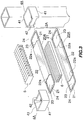
- This embodiment is an application of the present invention to an air-cooled oil cooler 11 for industrial devices such as compressors, and is shown in FIGS. 1 to 6.
- the oil cooler 11 comprises six oil channel members 2A arranged one above another in parallel at a spacing and each composed of a pair of plates 20A, two upper and lower side plates 3 disposed externally of and spaced apart from the respective oil channel members 2A at the upper and lower ends of the arrangement, annular header members 4A each interposed between each pair of adjacent oil channel members 2A at each of opposite lateral ends of the arrangement, an annular end header member 4B interposed between, each side plate 3 and the oil channel member 2A adjacent thereto at each of opposite lateral ends of the arrangement, outer fins 5 interposed between lengthwise intermediate portions of each pair of adjacent oil channel members 2A and between lengthwise intermediate portions of each side plate 3 and the oil channel member 2A adjacent thereto, inner fins 6 inserted in oil channels A of the respective oil channel members 2A, and two piping sockets 7 for connection to an oil inlet pipe and an oil outlet pipe, respectively.
- Each of the pair of plates 20A constituting the oil channel member 2A comprises a double-faced aluminum brazing sheet which is in the form of a laterally elongated rectangle when seen from above.
- the plate 20A has a generally square or rectangular oil passing hole 21 at each of opposite lateral ends thereof, and a channel portion 22 extending over the entire length thereof between the end holes 21 for forming the oil channel.
- the plate 20A has an opening 23 communicating with the header member 4A and formed by the hole 21 and an open end of the channel portion 22 which end is continuous with the hole.
- the plate 20A is made from a plate blank cut to a predetermined size by forming the two holes 21 and the channel portion 22, in the blank at the same time by press work.
- the die to be used for the work is preferably one dividable into two segments at the midportion of the length thereof. It is then possible to readily prepare plates 20A of different lengths as desired by interposing an intermediate die member between the divided die segments and using the resulting die for press work.
- the plate 20A may be prepared by forming the channel portion 22 in the plate blank cut to the predetermined size by press work and then forming the two holes 21 in the respective opposite ends of the plate blank similarly by press work.
- the length of plate 20A is then easily variable within the range of the sum of the lateral lengths of the two holes 21 even if a single kind of press die is used for forming the channel portion 22.
- Each side plate 3 comprises a double-faced or single-faced aluminum brazing sheet having the same contour as the plate 20A.
- the upper side plate 3 has an oil outlet bore 31 in its right end.
- the pair of plates 20A are brazed with she recessed faces of their channel portions 22 opposed to each other, whereby the oil channel member 2A is formed (see FIGS. 2 and 3).
- header members 4A are obtained by cutting a hollow aluminum extrudate of approximately square or rectangular cross section into lengths.
- Each of the upper and lower end faces of the header member 4A comprises a flat portion 41 to be fitted to a flat portion 24 of the hole-defining edge of each of the plates 20A paired to constitute the oil channel member 2A which portion 24 is approximately U-shaped when seen from above, and a recessed portion 42 to be fitted to a protuberant face of end 22a of channel portion 22 of the plate 20A (see FIGS. 2 and 3).
- These recessed portions 42 are formed by press work or cutting.
- the end header member 4B is obtained similarly from a hollow aluminum extrudate of approximately square or rectangular cross section.
- the end face to be opposed to the plate 20A comprises a flat portion 41 to be fitted to the flat portion 24 of the hole-defining edge of the plate 20A, and a recessed portion 42 to be fitted to the protuberant face of end 22a of channel portion 22 of the plate 20A.
- the other end face to be opposed to the side plate 3 comprises only a flat portion 41 to be fitted to the inner surface of the side plate 3 (see FIG. 2).
- each header member 4A is each brazed to the peripheral edge portion of the plate 20A immediately adjacent thereto and defining the opening 23 which comprises the hole 21 of the plate 20A and the open end of the channel portion 22 thereof for communication with the header member 4A
- one of the upper and lower end faces of each end header member 4B is brazed to the peripheral edge portion of the plate 20A immediately adjacent thereto and defining the opening 23 for communication with the member 4B
- the other end face is brazed to the inner surface of the side plate 3 immediately adjacent thereto.
- the outer fin 5 is in the form of a corrugated aluminum fin and has its crest portions and bottom portions brazed to the outer surfaces of pair of plates 20A constituting the oil channel member 2A.
- the inner fin 6 is similarly in the form of a corrugated aluminum fin and has its crest portions and bottom portions brazed to the inner surfaces of pair of plates 20A constituting the oil channel member 2A.
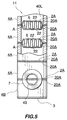
- the piping socket 7 is made of aluminum, is in the form of an annular member having an internally threaded portion, and is welded to the outer surfaces of left side walls of the end header member 4B positioned at the left lower end of the oil cooler 11 and the header member 4A adjacent to the member 4B, at edge portions of the walls defining a socket communication bore 43 (see FIGS. 1, 2, 4 and 5).
- the bore 43 is formed by semicircular cutouts 43B, 43A formed in the respective side walls of the end header member 4B and the header member 4A.
- the left ends of the pair of plates 20A positioned in the socket communication bore 43 have a relatively small thickness and will not offer great resistance to the passage of oil through the bore 43, therefore causing no trouble when the oil cooler 11 is used.
- the piping socket 7 is similarly made of aluminum, in the form of a generally annular member having an internally threaded portion and welded to the upper side plate 3 with its lower end portion of reduced outside diameter fitted in the socket communication bore 31 formed in the right end portion of the upper side plate 3 (see FIGS. 1 and 2).
- the oil cooler 11 can be obtained, for example, by assembling in a specified state the components, i.e., the plates 20A, side plates 3, header members 4A, end header members 4B, outer fins 5 and inner fins 6, joining the components collectively by vacuum brazing while restraining the assembly by a jig and welding the two piping sockets 7 individually to the header members 4A, 4B concerned and to the side plate 3, so that the cooler is available with high productivity.
- the piping socket 7 for connection to the oil outlet pipe can be joined to the side plate 3 by collective vacuum brazing.
- oil of high temperature flows into the oil cooler 11 described above through one of the bores, 43, and then into the oil channels A of the oil channel members 2A from the left rightward through the header H at the left end.
- the high-temperature oil flowing through the oil channels A undergoes heat exchange with air of low temperature flowing through the cooler transversely thereof between the lengthwise intermediate portions of the adjacent oil channel members 2A and between the lengthwise intermediate portions of the upper and lower side plates 3 and the lengthwise intermediate portions of the oil channel members 2A adjacent to the respective plates 3, whereby the oil is cooled.
- the cooled oil is thereafter run off from the other bore 31 through the header H at the right end.
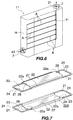
- FIGS. 7 to 9 show a modification of pair of plates 20A for forming the oil channel member 2A.
- the pair of plates 20A each have a vertical wall 27 extending longitudinally thereof along each of its front and rear edges between the left and right header members 4A so as to be in contact with the outer surfaces of these header members 4A for determining the inward position of the header members 4A.
- the channel portion 22 of each of the pair of plates 20A is formed at its opposite ends with respective vertical walls 28 extending transversely of the plate so as to be in contact with the inner surfaces of the respective left and right header members 4A for determining the outward position of these header members.
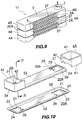
- FIGS. 10 and 11 show another modification of pair of plates 20A constituting the oil channel member 2A.
- the pair of plates 20A constituting the oil channel member 2A are each formed, along the edge defining each of the left and right holes 21, with a slanting wall 29 integral with the flat portion 24 and the channel portion 22 and to be positioned at an acute angle with the inner surface of the header member 4A.
- a sufficient amount of brazing material F can be filled in between the inner surface of the header member 4A and the inner surface of the slanting wall 2a to result in stabilized brasing.
- the left and right holes 21 are formed in respective left and right extensions of the bottom wall 22a of the channel, portion 22 which are flush with the wall 22a, whereas these extensions need not always be at the same level as the bottom wall 22a.
- this modification may be provided only with the vertical wall 27 for determining the outward position of each of the corresponding header members.
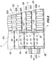
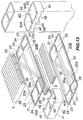
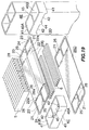
- This embodiment is an application of the present invention to a composite cooler which comprises an air-cooled oil cooler and an air-cooled after cooler in combination for industrial devices such as compressors, and is shown in FIGS. 12 to 15.
- This composite cooler 12 has the same construction as the first embodiment, i.e., the oil cooler 11, shown in FIGS. 1 to 6 with the exception of the following features.
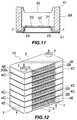
- plates 20B of the composite cooler 12 each have opposite lateral end holes 21 and a pair of striplike partitions 25 dividing the respective holes 21 each into front and rear two portions.
- the plates 20B has a channel portion 22 divided into front and rear two portions by a ridgelike partition 26 projecting in the form of a reverse channel toward the recessed side of the channel portion 22 and having a top wall 26a extending laterally so as to be integral with the striplike partitions 25.
- a pair of plates 20B are joined with the recessed surfaces of their channel portions 22 opposed to each other, whereby a compressed air-oil channel member 2B is formed.
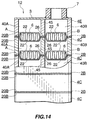
- Header members 4C each have a hollow portion divided into front and rear two portions by a vertical partition wall 43 corresponding to the striplike partition 25 of the plate 20B.
- a recessed portion 42 in each of the upper and lower end faces of each header member 4C is divided into front and rear two portions by a protruding partition 44 fittable in the recessed end of the ridgelike partition 26 of the plate 20B (see FIG. 8).
- End header members 4E also each have a hollow portion divided into front and rear two portions by a vertical partition wall 45 corresponding to the striplike partition 25 of the plate 20B.
- the end face to be opposed to the plate 20B has a recessed portion 42 which is divided into front and rear two portions by a protruding partition 44 fittable in the recessed end of the ridgelike partition 26 of the plate 20B.
- Each of the upper and lower end faces of the vertical partition wall 45 of the header member 4C is joined to the striplike partition 25 of the plate 20B opposed thereto, and the protruding partition 44 of the recessed portion 42 in each of the upper and lower end faces of the header member 4C is joined to the recessed end of the ridgelike partition 26 of the plate 20B opposed thereto (see FIGS. 12 to 14).
- Each of the upper and lower end faces of the vertical partition wall 45 of the end header member 4E is joined to the striplike partition 26 of the plate 20B opposed thereto or to the inner surface of a side plate 3 opposed thereto, and the protruding partition 44 of the recessed portion 42 formed in one of the upper and lower end faces of the end header member 4E is joined to the recessed end of the ridgelike partition 26 of the plate 20B opposed thereto.
- the composite cooler 12 comprises an after cooler portion provided by compressed air channels B at the front side, i.e., air upstream side, of the compressed air-oil channel members 2B and compressed air passing hollow portions 40B at the front side of the header members 4C, and an oil cooler portion provided by oil channels A at the rear side, i.e., air downstream side, of the fluid channel members 2B and oil passing hollow, portions 40A at the rear side of the header members 4C.
- Inner fins 6 are inserted in the front compressed air channels B and the rear oil channels A of the channel members 2B (see FIGS. 13 and 14).
- the lower side plate 3 has a compressed air inlet bore at a right-end front portion thereof and an oil inlet bore at a left-end rear portion thereof
- the upper side plate 3 has a compressed air outlet bore at a left-end front portion thereof and an oil outlet bore at a right-end rear portion thereof.
- a piping socket 7 is joined to the bore-defining peripheral edge portion of the plate in communication with each of these bores.
- the composite cooler 12 is fabricated by the same process as the oil cooler 1 of the first embodiment.
- compressed air having a high temperature and flowing into the after cooler portion of the composite cooler 12 from the compressed air inlet bore passes through a compressed air heater HB at the right end and then flows through the compressed air channels B of she channel members 2B from the right leftward.
- the compressed air of high temperature flowing through the air channels B undergoes heat exchange with air of low temperature flowing through the cooler from the front rearward between the lengthwise intermediate portions of each pair of adjacent channel members 2B and between the lengthwise intermediate portion of each of the upper and lower side plates 3 and the lengthwise intermediate portion of the channel member 2B adjacent thereto, through the plates 20B, outer fins 5 and inner fins 6, whereby the compressed air is cooled.
- the cooled compressed air thereafter flows through a compression air header HB at the left end and is run off from the compressed air outlet bore.
- oil having a high temperature and flowing into the oil cooler portion of the composite cooler 12 via the oil inlet bore passes through an oil header HA at the left end and then flows through the oil channels A of the channel members 2B from the left rightward.
- the oil of high temperature flowing through the oil channels A undergoes heat exchange with the air of low temperature, whereby the oil is cooled.
- the cooled oil thereafter flows through an oil header HA at the right end and is run off through the oil outlet bore.
- the second embodiment may be modified like the pair of modified plates of the first embodiment.
- the pair of plates 20B may each have a vertical wall 27 extending longitudinally thereof along each of its front and rear edges between the left and right header members 4C so as to be in contact with the outer surfaces of these header members 4C for determining the inward position of the header members 4C.
- the channel portion 22 of each of the pair of plates 20B may be formed at each of its opposite ends with two vertical walls 28 extending transversely of the plate and positioned at opposite sides of the ridgelike partition 26 so as to be in contact with the inner surface of the corresponding header member 4C for determining the outward position of the header member.
- the second embodiment may be further modified like another modification of pair of plates of the first embodiment.
- the pair of plates 20B constituting the compressed air-oil channel member 2B may each be formed, along the edge defining each of the left and right holes 21, with a slanting wall 29 integral with the flat portion 24 and the channel portion 22 and to be positioned at an acute angle with the inner surface of the header member 4C.
- the slanting wall 29 makes an acute angle also with the surface of the vertical partition wall 45 and is integral with the striplike partition 25.
- the upper plate 20B only is shown in FIG. 16; the lower plate is symmetrical to the upper plate. According to this modification, a sufficient amount of brazing material F can be filled in between the outer surface of the slanting wall 29 and the inner surface of the header member 4C and between the slanting wall outer surface and the surface of the partition wall 45 opposed thereto.
- the left and right holes 21 are formed in respective left and right extensions of the bottom wall 22a of the channel portion 22 which are flush with the wall 22a, whereas these extensions need not always be at the same level as the bottom wall 22a.
- this modification may have only, the vertical walls 27 indicated in chains lines in FIG. 16 and formed in the same manner as described with reference to FIG. 13 for determining the outward position of the corresponding header member..
- This embodiment is an application of the present invention to an air-cooled oil cooler for industrial devices such as compressors, and is shown in FIG. 17.
- This oil cooler 13 has the same construction as the second embodiment, i.e., the composite cooler 12, shown in FIGS. 12 to 15 with the exception of the following feature.
- the oil cooler 13 has at the right end thereof header members 4D and end header members (not shown) which have no vertical partition walls 45. Accordingly, front and rear two headers H are formed at the left end of the oil cooler, and one header H is formed at the right end thereof.
- the lower side plate 3 of the oil cooler 13 has an oil inlet bore at a left-end rear portion thereof, and the upper side plate 3 has an oil outlet bore at the left-end front portion.
- a piping socket 7 is joined to the peripheral edge portion of the plate defining each of these bores.
- oil having a high temperature and flowing into the oil cooler 13 via the oil inlet bore passes through the rear header H at the left end and then flows through the rear oil channels A of the oil channel members 2B from the left rightward into the header H at the right end, from which the oil flows through the front oil channels A of the oil channel members 2B from the right leftward in countercurrent relation with the oil flow through the rear oil channels A.
- the oil of high temperature flowing through the front and rear oil channels A undergoes heat exchange with air of low temperature flowing through the cooler from the front rearward between the lengthwise intermediate portions of each pair of adjacent oil channel members 2B and between the lengthwise intermediate portion of each of the upper and lower side plates 3 and the lengthwise intermediate portion of the oil channel member 2B adjacent thereto, through the plates 20B, outer fins 5 and inner fins 6, whereby the oil is cooled.
- the cooled oil thereafter flows through the front header H at the left end and is run off from the oil outlet bore.
- the oil cooler 13 is so adapted that the oil flows through the front and rear oil channels A of the oil channel members 2B in countercurrent relation as described above, therefore achieves an improved heat exchange efficiency and can consequently be compacted.
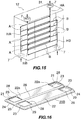
- This embodiment is an application of the present invention to an air-cooled oil cooler for industrial devices such as compressors, and is shown in FIGS. 18.
- This oil cooler has the same construction as the first embodiment, i.e., the oil cooler 11, shown in FIGS. 1 to 6 with the exception of the following feature.
- the oil cooler comprises oil channel members 2C each comprising an upper first plate 20A having the same construction as the plate 20A shown in FIGS. 1 to 6, and a flat lower second plate 20C having a fluid passing hole 21 at each of opposite lateral ends thereof. These plates are joined with the recessed surface of the channel portion 22 of the first plate 20A down to form the fluid channel member 2C.
- Header members 4B each interposed between each pair of adjacent fluid channel members 2C at each of opposite lateral ends of the cooler have the same construction as the end header member 4B of the oil cooler 11 according to the first embodiment.
- the header member, 4B has an upper face which comprises a flat portion 41 to be fitted to the outer surface of the peripheral edge portion of the second plate 20C defining the end hole 21 thereof.
- the upper end face of the header member 4B is joined to the hole-defining peripheral edge portion of the second plate 20C opposed thereto.
- the lower end face of the header member 4B is joined to the peripheral edge portion of the first plate 20A opposed thereto and defining an opening 23 formed by the end hole 21 of the first plate 20A and the open end of the channel portion 22 thereof for communication with the header member.
- the second plate 20C need not be formed with the channel portion.
- the upper and lower end faces of the header member 4B only the lower end face to be opposed to the first plate 20A needs to be worked on to form a recess portion 42. Accordingly, the number of working steps can be correspondingly decreased to achieve improved productivity.
- first plate 20A and the second plate 20C of the fourth embodiment described may each have a vertical wall 27 extending longitudinally thereof along each of front and rear edges the plate between the corresponding pair of laterally opposed header members 4B so as to be in contact with outer surfaces of the opposed header members 4B for determining the inward position of the opposed header members.
- the channel portion 22 of the first plate 20A and the inner portion of the second plate 20C defining the opposite end holes 21 may each be formed at opposite ends thereof with respective vertical walls 28 extending transversely of the plate so as to be in contact with inner surfaces of the corresponding pair of laterally opposed header members 4B for determining the outward position of the opposed header members.
- the first plate 20A of the fourth embodiment may be formed, along the edge defining each of the left and right holes 21, with a slanting wall 29 integral with the flat portion 24 and the channel portion 22 and to be positioned at an acute angle with the inner surface of the header member 4B.
- the first plate 20A and the second plate 20C may be formed with vertical walls 28 for determining the outward position of the header member 4B.
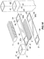
- This embodiment is an application of the present invention to a composite cooler which comprises an air-cooled oil cooler and an air-cooled after cooler in combination for industrial devices such as compressors, and is shown in FIG. 19.
- This composite cooler has the same construction as the second embodiment, i.e., the composite cooler 12, shown in FIGS. 12 to 15 as the first embodiment with the exception of the following features.
- This composite cooler comprises compressed air-oil channel members 2D each comprising an upper first plate 20B having the same construction as the plate 20B shown in FIGS. 12 to 14, and a flat lower second plate 20D having a fluid passing hole 21 at each of opposite lateral ends thereof, with the end hole 21 divided into front and rear two portions by a striplike partition 25 extending longitudinally of the plate.
- compressed air-oil channel members 2D each comprising an upper first plate 20B having the same construction as the plate 20B shown in FIGS. 12 to 14, and a flat lower second plate 20D having a fluid passing hole 21 at each of opposite lateral ends thereof, with the end hole 21 divided into front and rear two portions by a striplike partition 25 extending longitudinally of the plate.
- Header members 4E each interposed between each pair of adjacent compressed air-coil channel members 2D at each of opposite lateral ends of the cooler have the same construction as the end header member 4B of the composite cooler 12 according to the second embodiment.
- the header member 4E has an upper face which comprises a flat portion 41 to be fitted to the peripheral edge portion of the second plate 20D defining the end hole 21 thereof.
- the upper end face of the header member 4E is joined to the hole-defining peripheral edge portion of the second plate 20D opposed thereto.
- the lower end face of the header member 4E is joined to the peripheral edge portion of the first plate 20B opposed thereto and defining an opening 23 formed by the end hole 21 of the first plate 20B and the open end of the channel portion 22 thereof for communication with the header member 4E.
- Each of the upper and lower end faces of the vertical partition wall 45 of the header member 4E is joined to the striplike partition 25 of the second or first plate 20D or 20B opposed thereto, and the protruding partition 44 of the recessed portion 42 in the lower end face of the header member 4E is joined to the recessed end of the ridgelike partition 26 of the first plate 20B opposed thereto.
- the second plate 20D need not be formed with the channel portion 22.
- the header member 4E Of the upper and lower end faces of the header member 4E, only the lower end face to be opposed to the first plate 20B needs to be worked on to form a recess portion 42. Accordingly, the number of working steps can be correspondingly decreased to achieve improved productivity.
- first plate 20B and the second plate 20D of the fifth embodiment described may each have a vertical wall 27 extending longitudinally thereof along each of front and rear edges the plate between the corresponding pair of laterally opposed header members 4E so as to be in contact with outer surfaces of the opposed header members 4E for determining the inward position of the opposed header members.
- the channel portion 22 of the first plate 20B and the inner portion of the second plate 20C defining the opposite end holes 21 may each be formed at opposite ends thereof with respective vertical walls 28 extending transversely of the plate so as to be in contact with inner surfaces of the corresponding pair of laterally opposed header members 4E for determining the outward position of the opposed header members.
- the first plate 20B of the fifth embodiment may be formed, along the edge defining each of the left and right holes 21, with a slanting wall 29 integral with the flat portion 24 and the channel portion 22 and to be positioned at an acute angle with the inner surface of the header member 4E.
- the slanting wall 29 makes an acute angle also with the surface of the vertical partition wall 45 and is integral with the striplike partition 25.
- the heat exchangers of the present invention are useful as air-cooled oil coolers or air-cooled after coolers for various industrial devices, or as composite coolers comprising an air-cooled oil cooler and an air-cooled after cooler in combination for industrial devices such as compressors.
Landscapes
- Engineering & Computer Science (AREA)
- Physics & Mathematics (AREA)
- Thermal Sciences (AREA)
- Mechanical Engineering (AREA)
- General Engineering & Computer Science (AREA)
- Heat-Exchange Devices With Radiators And Conduit Assemblies (AREA)
- Separation By Low-Temperature Treatments (AREA)
- Power Steering Mechanism (AREA)
- Compression-Type Refrigeration Machines With Reversible Cycles (AREA)
Applications Claiming Priority (5)
| Application Number | Priority Date | Filing Date | Title |
|---|---|---|---|
| JP32519596 | 1996-12-05 | ||
| JP32519596 | 1996-12-05 | ||
| JP8031497 | 1997-03-31 | ||
| JP8031497 | 1997-03-31 | ||
| PCT/JP1997/004465 WO1998025093A1 (en) | 1996-12-05 | 1997-12-05 | Heat exchanger |
Publications (3)
| Publication Number | Publication Date |
|---|---|
| EP0943884A1 true EP0943884A1 (de) | 1999-09-22 |
| EP0943884A4 EP0943884A4 (de) | 2000-05-17 |
| EP0943884B1 EP0943884B1 (de) | 2003-04-02 |
Family
ID=26421340
Family Applications (1)
| Application Number | Title | Priority Date | Filing Date |
|---|---|---|---|
| EP97946121A Expired - Lifetime EP0943884B1 (de) | 1996-12-05 | 1997-12-05 | Wärmetauscher |
Country Status (6)
| Country | Link |
|---|---|
| US (1) | US6170567B1 (de) |
| EP (1) | EP0943884B1 (de) |
| AT (1) | ATE236381T1 (de) |
| DE (1) | DE69720506T2 (de) |
| ES (1) | ES2192698T3 (de) |
| WO (1) | WO1998025093A1 (de) |
Cited By (3)
| Publication number | Priority date | Publication date | Assignee | Title |
|---|---|---|---|---|
| WO2004023056A1 (de) * | 2002-08-13 | 2004-03-18 | Behr Gmbh & Co. | Wärmeübertrager |
| WO2012110036A1 (en) | 2011-02-18 | 2012-08-23 | Nissens A/S | Method of producing a heat exchanger and a heat exchanger |
| RU2614307C2 (ru) * | 2012-05-28 | 2017-03-24 | Кейтерпиллар Инк. | Теплообменник и машина, снабженная таким теплообменником |
Families Citing this family (30)
| Publication number | Priority date | Publication date | Assignee | Title |
|---|---|---|---|---|
| JP2001021287A (ja) * | 1999-07-08 | 2001-01-26 | Zexel Valeo Climate Control Corp | 熱交換器 |
| JP4368037B2 (ja) * | 2000-04-26 | 2009-11-18 | 本田技研工業株式会社 | 不整地走行用四輪車 |
| US6568466B2 (en) | 2000-06-23 | 2003-05-27 | Andrew Lowenstein | Heat exchange assembly |
| US6341649B1 (en) * | 2001-02-12 | 2002-01-29 | Delphi Technologies, Inc. | Aluminum plate oil cooler |
| KR20030080004A (ko) * | 2001-02-19 | 2003-10-10 | 쇼와 덴코 가부시키가이샤 | 열교환기 |
| US20040050531A1 (en) * | 2001-02-19 | 2004-03-18 | Hirofumi Horiuchi | Heat exchanger |
| CN1620588A (zh) * | 2001-12-27 | 2005-05-25 | 达纳加拿大公司 | 具有内部带槽歧管的热交换器 |
| FR2834336B1 (fr) * | 2001-12-28 | 2006-12-01 | Valeo Thermique Moteur Sa | Element de circuit pour echangeur de chaleur, notamment de vehicule automobile et echangeur de chaleur ainsi obtenu |
| CN100368755C (zh) * | 2002-10-11 | 2008-02-13 | 昭和电工株式会社 | 流体从中流过的扁平空心体部、包含该空心体部的热交换器以及制造该热交换器的方法 |
| EP1549895A4 (de) * | 2002-10-11 | 2012-01-18 | Showa Denko Kk | Flacher hohlkörper zum durchlassen von fluid dadurch, wärmetauscher mit dem hohlkörper und verfahren zur herstellung des wärmetauschers |
| AT7133U1 (de) * | 2003-01-29 | 2004-10-25 | Werner Dipl Ing Pustelnik | Plattenkühler |
| JP3961443B2 (ja) * | 2003-04-08 | 2007-08-22 | 本田技研工業株式会社 | 蒸発器 |
| KR100537666B1 (ko) * | 2003-06-27 | 2005-12-20 | 현대자동차주식회사 | 자동차의 오일쿨러 |
| CN100414245C (zh) * | 2003-12-22 | 2008-08-27 | 昭和电工株式会社 | 热交换器及其制造方法 |
| SE527716C2 (sv) * | 2004-04-08 | 2006-05-23 | Swep Int Ab | Plattvärmeväxlare |
| EP1593923B1 (de) * | 2004-05-06 | 2007-01-03 | Movi Alluminium S.r.l. | Wärmetauscher |
| JP4493407B2 (ja) * | 2004-05-27 | 2010-06-30 | サンデン株式会社 | 積層型熱交換器およびその製造方法 |
| EP1870658A1 (de) | 2006-06-20 | 2007-12-26 | Delphi Technologies, Inc. | Wärmetauscher und Verfahren zum Herstellen eines Wärmetauschers |
| WO2008086562A1 (en) * | 2007-01-16 | 2008-07-24 | Permo-Drive Technologies Ltd | Drive assembly for a regenerative drive system |
| US8371365B2 (en) * | 2007-05-03 | 2013-02-12 | Brayton Energy, Llc | Heat exchange device and method for manufacture |
| AT505413B1 (de) * | 2007-08-21 | 2009-01-15 | Pustelnik Philipp Dipl Ing | Plattenkühler für flüssigkeiten |
| US8678076B2 (en) * | 2007-11-16 | 2014-03-25 | Christopher R. Shore | Heat exchanger with manifold strengthening protrusion |
| WO2009127063A1 (en) * | 2008-04-17 | 2009-10-22 | Dana Canada Corporation | U-flow heat exchanger |
| JP5408017B2 (ja) | 2009-06-05 | 2014-02-05 | 株式会社デンソー | 蓄冷熱交換器 |
| US20110132570A1 (en) * | 2009-12-08 | 2011-06-09 | Wilmot George E | Compound geometry heat exchanger fin |
| NO334102B1 (no) * | 2010-09-07 | 2013-12-09 | Pleat As | Varmeveksler |
| JP6623912B2 (ja) * | 2015-04-30 | 2019-12-25 | 株式会社デンソー | 蒸発器 |
| US10006643B1 (en) * | 2017-04-14 | 2018-06-26 | Scandic Builders, Inc. | Technologies for underfloor fluid conduction |
| WO2018209439A1 (en) * | 2017-05-16 | 2018-11-22 | Dana Canada Corporation | Counterflow heat exchanger with side entry fittings |
| FR3086381B1 (fr) * | 2018-09-25 | 2022-05-20 | Valeo Systemes Thermiques | Adaptateur pour collecteur d'un echangeur de chaleur |
Family Cites Families (19)
| Publication number | Priority date | Publication date | Assignee | Title |
|---|---|---|---|---|
| GB859837A (en) | 1958-05-14 | 1961-01-25 | Morris Motors Ltd | Improvements relating to plate-type heat-exchangers |
| US3017161A (en) * | 1959-01-12 | 1962-01-16 | Modine Mfg Co | Heat exchanger |
| GB1297784A (de) * | 1969-04-10 | 1972-11-29 | ||
| US3805889A (en) * | 1973-05-04 | 1974-04-23 | United Aircraft Prod | Plate type heat exchanger |
| JPS5623700A (en) * | 1979-08-03 | 1981-03-06 | Fuji Heavy Ind Ltd | Heat exchanger |
| US4258785A (en) * | 1980-02-08 | 1981-03-31 | Borg-Warner Corporation | Heat exchanger interplate fitting |
| IT1179639B (it) * | 1984-05-04 | 1987-09-16 | Piemontese Radiatori | Radiatore per autoveicoli |
| JPS61173097A (ja) * | 1985-01-25 | 1986-08-04 | Nippon Denso Co Ltd | 熱交換器の製造方法 |
| JPS63167090U (de) * | 1987-04-10 | 1988-10-31 | ||
| FR2625301A3 (fr) | 1987-12-23 | 1989-06-30 | Valeo Chausson Thermique | Echangeur de chaleur a plaques, notamment pour vehicule automobile, et procede de fabrication permettant d'obtenir un tel echangeur |
| US4846268A (en) * | 1988-01-12 | 1989-07-11 | Thermag Industries Inc. | Heat exchanger with individual twinplate headers |
| JPH0619965Y2 (ja) * | 1988-01-22 | 1994-05-25 | サンデン株式会社 | 熱交換器 |
| JPH0269275U (de) * | 1988-11-02 | 1990-05-25 | ||
| JPH02133567U (de) * | 1989-03-31 | 1990-11-06 | ||
| SE462763B (sv) * | 1989-04-28 | 1990-08-27 | Torell Ab | Plattvaermevaexlare/kylare samt saett att tillverka denna |
| JPH0492180U (de) * | 1990-12-26 | 1992-08-11 | ||
| JPH0674672A (ja) * | 1992-08-25 | 1994-03-18 | Hisaka Works Ltd | プレート式熱交換器 |
| FR2721099B1 (fr) * | 1994-06-08 | 1996-07-19 | Valeo Thermique Moteur Sa | Echangeur de chaleur utile notamment pour le refroidissement d'un flux d'air à haute température. |
| US5638900A (en) * | 1995-01-27 | 1997-06-17 | Ail Research, Inc. | Heat exchange assembly |
-
1997
- 1997-12-05 WO PCT/JP1997/004465 patent/WO1998025093A1/ja not_active Ceased
- 1997-12-05 AT AT97946121T patent/ATE236381T1/de not_active IP Right Cessation
- 1997-12-05 EP EP97946121A patent/EP0943884B1/de not_active Expired - Lifetime
- 1997-12-05 US US09/319,320 patent/US6170567B1/en not_active Expired - Fee Related
- 1997-12-05 DE DE69720506T patent/DE69720506T2/de not_active Expired - Fee Related
- 1997-12-05 ES ES97946121T patent/ES2192698T3/es not_active Expired - Lifetime
Cited By (3)
| Publication number | Priority date | Publication date | Assignee | Title |
|---|---|---|---|---|
| WO2004023056A1 (de) * | 2002-08-13 | 2004-03-18 | Behr Gmbh & Co. | Wärmeübertrager |
| WO2012110036A1 (en) | 2011-02-18 | 2012-08-23 | Nissens A/S | Method of producing a heat exchanger and a heat exchanger |
| RU2614307C2 (ru) * | 2012-05-28 | 2017-03-24 | Кейтерпиллар Инк. | Теплообменник и машина, снабженная таким теплообменником |
Also Published As
| Publication number | Publication date |
|---|---|
| EP0943884A4 (de) | 2000-05-17 |
| WO1998025093A1 (en) | 1998-06-11 |
| ES2192698T3 (es) | 2003-10-16 |
| US6170567B1 (en) | 2001-01-09 |
| DE69720506D1 (de) | 2003-05-08 |
| DE69720506T2 (de) | 2004-03-04 |
| ATE236381T1 (de) | 2003-04-15 |
| EP0943884B1 (de) | 2003-04-02 |
Similar Documents
| Publication | Publication Date | Title |
|---|---|---|
| EP0943884B1 (de) | Wärmetauscher | |
| EP0947796B1 (de) | Lamellenwärmetauscher mit Rohrverbindung | |
| US6446713B1 (en) | Heat exchanger manifold | |
| US6073688A (en) | Flat tubes for heat exchanger | |
| JP4065781B2 (ja) | 熱交換器、これを用いたカー・エアコン、及び熱交換器を備えた自動車 | |
| EP0724125A2 (de) | Flachrohr für Wärmetauscher und Verfahren zu dessen Herstellung | |
| US7219720B2 (en) | Flat hollow body for passing fluid therethrough, heat exchanger comprising the hollow body and process for fabricating the heat exchanger | |
| JPS61262593A (ja) | 熱交換器 | |
| WO1995018947A1 (en) | Modular extruded aluminum heat exchanger | |
| JPH0566073A (ja) | 積層型熱交換器 | |
| KR20010086012A (ko) | 플레이트식 열교환기 및 그 제조방법 | |
| US20020153129A1 (en) | Integral fin passage heat exchanger | |
| US6364006B1 (en) | Beaded plate for a heat exchanger and method of making same | |
| KR20030080233A (ko) | 열 교환기 | |
| US7222664B2 (en) | Heat exchanger plate and this exchanger | |
| EP1067350B1 (de) | Platte mit Wulsten für Wärmetauscher und deren Herstellung | |
| JP2586753Y2 (ja) | 熱交換器 | |
| JP2016161161A (ja) | 熱交換器 | |
| US20070074859A1 (en) | Heat exchanger and process for fabricating same | |
| JP4164146B2 (ja) | 熱交換器、及びこれを用いたカー・エアコン | |
| JP3393392B2 (ja) | 熱交換器 | |
| JP3837621B2 (ja) | 積層型熱交換器およびその製造方法 | |
| WO2021241544A1 (ja) | 伝熱管、熱交換器、熱源ユニットおよび伝熱管の製造方法 | |
| JPH10332284A (ja) | 熱交換器 | |
| CN100368755C (zh) | 流体从中流过的扁平空心体部、包含该空心体部的热交换器以及制造该热交换器的方法 |
Legal Events
| Date | Code | Title | Description |
|---|---|---|---|
| PUAI | Public reference made under article 153(3) epc to a published international application that has entered the european phase |
Free format text: ORIGINAL CODE: 0009012 |
|
| 17P | Request for examination filed |
Effective date: 19990702 |
|
| AK | Designated contracting states |
Kind code of ref document: A1 Designated state(s): AT BE CH DE ES FR GB IT LI NL SE |
|
| A4 | Supplementary search report drawn up and despatched |
Effective date: 20000404 |
|
| AK | Designated contracting states |
Kind code of ref document: A4 Designated state(s): AT BE CH DE ES FR GB IT LI NL SE |
|
| RAP1 | Party data changed (applicant data changed or rights of an application transferred) |
Owner name: SHOWA DENKO KABUSHIKI KAISHA |
|
| 17Q | First examination report despatched |
Effective date: 20010814 |
|
| GRAG | Despatch of communication of intention to grant |
Free format text: ORIGINAL CODE: EPIDOS AGRA |
|
| GRAG | Despatch of communication of intention to grant |
Free format text: ORIGINAL CODE: EPIDOS AGRA |
|
| GRAG | Despatch of communication of intention to grant |
Free format text: ORIGINAL CODE: EPIDOS AGRA |
|
| GRAH | Despatch of communication of intention to grant a patent |
Free format text: ORIGINAL CODE: EPIDOS IGRA |
|
| GRAH | Despatch of communication of intention to grant a patent |
Free format text: ORIGINAL CODE: EPIDOS IGRA |
|
| GRAA | (expected) grant |
Free format text: ORIGINAL CODE: 0009210 |
|
| AK | Designated contracting states |
Designated state(s): AT BE CH DE ES FR GB IT LI NL SE |
|
| REG | Reference to a national code |
Ref country code: GB Ref legal event code: FG4D |
|
| REG | Reference to a national code |
Ref country code: CH Ref legal event code: EP |
|
| REF | Corresponds to: |
Ref document number: 69720506 Country of ref document: DE Date of ref document: 20030508 Kind code of ref document: P |
|
| REG | Reference to a national code |
Ref country code: SE Ref legal event code: TRGR |
|
| REG | Reference to a national code |
Ref country code: ES Ref legal event code: FG2A Ref document number: 2192698 Country of ref document: ES Kind code of ref document: T3 |
|
| ET | Fr: translation filed | ||
| PLBE | No opposition filed within time limit |
Free format text: ORIGINAL CODE: 0009261 |
|
| STAA | Information on the status of an ep patent application or granted ep patent |
Free format text: STATUS: NO OPPOSITION FILED WITHIN TIME LIMIT |
|
| 26N | No opposition filed |
Effective date: 20040105 |
|
| PGFP | Annual fee paid to national office [announced via postgrant information from national office to epo] |
Ref country code: GB Payment date: 20061129 Year of fee payment: 10 |
|
| PGFP | Annual fee paid to national office [announced via postgrant information from national office to epo] |
Ref country code: SE Payment date: 20061206 Year of fee payment: 10 |
|
| PGFP | Annual fee paid to national office [announced via postgrant information from national office to epo] |
Ref country code: FR Payment date: 20061208 Year of fee payment: 10 |
|
| PGFP | Annual fee paid to national office [announced via postgrant information from national office to epo] |
Ref country code: CH Payment date: 20061213 Year of fee payment: 10 Ref country code: AT Payment date: 20061213 Year of fee payment: 10 |
|
| PGFP | Annual fee paid to national office [announced via postgrant information from national office to epo] |
Ref country code: NL Payment date: 20061217 Year of fee payment: 10 |
|
| PGFP | Annual fee paid to national office [announced via postgrant information from national office to epo] |
Ref country code: ES Payment date: 20061228 Year of fee payment: 10 |
|
| PGFP | Annual fee paid to national office [announced via postgrant information from national office to epo] |
Ref country code: IT Payment date: 20061231 Year of fee payment: 10 |
|
| REG | Reference to a national code |
Ref country code: CH Ref legal event code: PL |
|
| EUG | Se: european patent has lapsed | ||
| GBPC | Gb: european patent ceased through non-payment of renewal fee |
Effective date: 20071205 |
|
| PG25 | Lapsed in a contracting state [announced via postgrant information from national office to epo] |
Ref country code: AT Free format text: LAPSE BECAUSE OF NON-PAYMENT OF DUE FEES Effective date: 20071205 |
|
| PGFP | Annual fee paid to national office [announced via postgrant information from national office to epo] |
Ref country code: BE Payment date: 20080314 Year of fee payment: 11 |
|
| NLV4 | Nl: lapsed or anulled due to non-payment of the annual fee |
Effective date: 20080701 |
|
| PG25 | Lapsed in a contracting state [announced via postgrant information from national office to epo] |
Ref country code: SE Free format text: LAPSE BECAUSE OF NON-PAYMENT OF DUE FEES Effective date: 20071206 Ref country code: LI Free format text: LAPSE BECAUSE OF NON-PAYMENT OF DUE FEES Effective date: 20071231 Ref country code: CH Free format text: LAPSE BECAUSE OF NON-PAYMENT OF DUE FEES Effective date: 20071231 |
|
| REG | Reference to a national code |
Ref country code: FR Ref legal event code: ST Effective date: 20081020 |
|
| PG25 | Lapsed in a contracting state [announced via postgrant information from national office to epo] |
Ref country code: NL Free format text: LAPSE BECAUSE OF NON-PAYMENT OF DUE FEES Effective date: 20080701 |
|
| PG25 | Lapsed in a contracting state [announced via postgrant information from national office to epo] |
Ref country code: GB Free format text: LAPSE BECAUSE OF NON-PAYMENT OF DUE FEES Effective date: 20071205 |
|
| REG | Reference to a national code |
Ref country code: ES Ref legal event code: FD2A Effective date: 20071207 |
|
| PG25 | Lapsed in a contracting state [announced via postgrant information from national office to epo] |
Ref country code: FR Free format text: LAPSE BECAUSE OF NON-PAYMENT OF DUE FEES Effective date: 20071231 Ref country code: ES Free format text: LAPSE BECAUSE OF NON-PAYMENT OF DUE FEES Effective date: 20071207 |
|
| PGFP | Annual fee paid to national office [announced via postgrant information from national office to epo] |
Ref country code: DE Payment date: 20081127 Year of fee payment: 12 |
|
| BERE | Be: lapsed |
Owner name: *SHOWA DENKO K.K. Effective date: 20081231 |
|
| PG25 | Lapsed in a contracting state [announced via postgrant information from national office to epo] |
Ref country code: IT Free format text: LAPSE BECAUSE OF NON-PAYMENT OF DUE FEES Effective date: 20071205 |
|
| PG25 | Lapsed in a contracting state [announced via postgrant information from national office to epo] |
Ref country code: BE Free format text: LAPSE BECAUSE OF NON-PAYMENT OF DUE FEES Effective date: 20081231 |
|
| PG25 | Lapsed in a contracting state [announced via postgrant information from national office to epo] |
Ref country code: DE Free format text: LAPSE BECAUSE OF NON-PAYMENT OF DUE FEES Effective date: 20100701 |