EP0943949A1 - Système de détermination et de quantification de l'alignement d'un objet avec une optique de couplage et un dispositif de prise de vues - Google Patents
Système de détermination et de quantification de l'alignement d'un objet avec une optique de couplage et un dispositif de prise de vues Download PDFInfo
- Publication number
- EP0943949A1 EP0943949A1 EP99400618A EP99400618A EP0943949A1 EP 0943949 A1 EP0943949 A1 EP 0943949A1 EP 99400618 A EP99400618 A EP 99400618A EP 99400618 A EP99400618 A EP 99400618A EP 0943949 A1 EP0943949 A1 EP 0943949A1
- Authority
- EP
- European Patent Office
- Prior art keywords
- image
- alignment
- plane
- light
- object plane
- Prior art date
- Legal status (The legal status is an assumption and is not a legal conclusion. Google has not performed a legal analysis and makes no representation as to the accuracy of the status listed.)
- Granted
Links
Images

Classifications
-
- G—PHYSICS
- G02—OPTICS
- G02B—OPTICAL ELEMENTS, SYSTEMS OR APPARATUS
- G02B7/00—Mountings, adjusting means, or light-tight connections, for optical elements
- G02B7/28—Systems for automatic generation of focusing signals
Definitions
- the invention relates to a system for determine if an object which one seeks to achieve a image is aligned with a coupling optic and a image acquisition device and, in case of non-alignment, to quantify the setting of positioning to be performed on the elements of the system to get this alignment.
- the invention finds applications in all areas relating to the creation of optimum quality of an object on an image plane, at through an optic and, in particular, to the field medical.
- the image plane i.e. the plane in which is the image acquisition device
- the coupling optics and, on the other hand, with the object.
- this alignment is difficult to achieve because it requires adjust the orthogonality of the image plane with the axis optical, as well as the focal length.
- the object can be at one variable distance from the optics; adjustment optics / image plane can therefore be done either approximate, either visually by the operator, thanks to telemetric or reflex sighting means.
- Some image capture devices are even with a distance measuring system object / optics which determines the distance between the object and optics by an ultrasonic method or infrared; in this case, the optical / image-plane adjustment is performed automatically.
- the object of the invention is precisely to remedy the disadvantages of the techniques described previously. To this end, it offers a system which determines alignment or non-alignment of an object with the coupling optics and the device image acquisition and, in the case of a non-alignment, to quantify the adjustments to be made on the system to get the alignment of these elements.
- the system of the invention uses an image acquisition device as well that a light source to create a set of bright spots and an opaque mask pierced with at least two holes to let the light through, the images of these light points on the image plane being split in the case of a non-alignment of the system.
- An analysis of these split images then allows quantify the setting to be made on the system to get alignment.
- the mask is placed in the focal plane optical coupling means.
- the holes of the mask are of small dimension, so that the dimension of the image of each light point on the image plane, of the same order of magnitude as the system resolution on the object plane, two to three times the value of the resolution.
- the system comprises an object support transparent to light radiation and defining the object plane.
- the object plane is virtual.
- the system of the invention can include, in addition, one or more mirror (s) positioned between the object plane and the acquisition device.
- the invention relates to a system for determine the alignment or non-alignment between a object to be imaged, a coupling optic and a image acquisition device which defines the system image map.
- the optics of coupling just like during the shooting, the optics of coupling, more simply called “optical”, focuses on this object plane.
- the objective of the system of the invention is to produce an image duplication of the image of a luminous point placed in the object plane, in the case where the alignment between the object, the optics of coupling and the image plane is not obtained, which corresponds to an incorrect system setting.
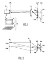
- the system of the invention shown in Figure 1, has a source light 1 which emits at least one light point la.
- This light source is placed in the object plane (noted Po) of the optical system and in the place where will be positioned the object during the shooting phase.
- the object plane In the case where the object plane is materialized by an object support, it must be transparent to radiation emitted by the source bright.
- the object carrier that defines the object plane can be made of Plexiglas®.
- the system of the invention further comprises an image acquisition device 2 which is provided with means for adjusting one's own position.
- These means of position adjustment can simply be mechanical means, such as a set of three knobs; they are not shown in the figure to simplify the figure.
- the acquisition device can be, by example, a "CCD detector”.
- the focus on object plane is related to the position of the CCD detector by compared to the coupling optics located between the object plane and image plane.
- the system of the invention further comprises a coupling optic 3 placed between the object plane Po and the image plane Pi; this coupling optic, more simply called “lens”, allows to couple an image created in the object plane with the image obtained in the image plane.
- the system of the invention includes a mask 4 opaque to radiation emitted by the light source and advantageously placed at the near the focal plane Pf of the system or at near optics 3.
- This mask is pierced with minus two holes 5a and 5b which ensure transmission at least partial of the light emitted by the source light 1.
- the mask holes each define a different direction of the incident radiation, which causes the doubling of the image of the bright spots on the Pi image plane, in the case of a misalignment.
- the light points from from the source are small, so that their diameter is of the same order of magnitude as the system resolution at the object plane level; they are, for example, two to three times the system resolution.
- the light emitted by the bright spots should not be focused.
- the mask also has the role of limiting the amount of light on the CCD detector, so that reduce the size of the light points defining so more precisely the geometric position of these bright spots.
- this mask is removable; indeed, it is used only during the step alignment.
- the system of the invention further comprises calculation means 6 which make it possible to quantify the non-alignment, i.e. quantifying the settings to be performed on the system to obtain the alignment of the system.
- calculation means can be means conventional computing such as a PC.
- one or more mirrors can be included in the optical path between the object plane and the image plan. So it is possible, in some applications, to use an optical path non-linear.
- FIG 2 there is shown schematically the optical path of the light points 1a and 1b emitted by the light source. These two points light 1a and 1b emitted by the light source is project at 2a and 2b on the image plane Pi, that is to say on the image acquisition device, after an optical path through the coupling optics 3.
- the device image acquisition 2 is aligned with the source light 1 and optics 3, since all the rays light emitted by each point of the object plane 1a and 1b converge on a single point of the image plane, respectively 2a and 2b.
- the incident light rays parallel to the optical axis of the lens (shown in solid lines) and which all pass through the point focal Fa.
- the incident rays oblique and parallel to each other pass through another point single focal Fb. So, at each focal point Fa and Fb of the focal plane Pf corresponds to a direction of rays incidents.
- mask 4 is placed advantageously in the focal plane Pf or in its neighborhood and only lets light through the holes 5a and 5b which correspond to the focal points Fa and Fb.
- CCD detector 2 is placed correctly in relation to optics 3 and to the object plane Po, that is to say if the three elements are aligned, then the image of the point there is point 2a.
- the image of the bright spot will be a set of two points on the CCD detector.
- the distance between the two image points of the point the light will be proportional to the distance of focusing of the CCD detector.
- Mask 4 then allows find the flatness and focus adjustment of the system which, for all the light points emitted by the light source, brings the most possible the images of the double light points on the Pi image plane defined by the CCD detector.
- the light source 1 is a test pattern consisting of a matrix of light points, such as light emitting diodes (or LEDs) placed on a support.
- FIG. 3 an example is shown target consisting of a matrix of n diodes placed on a disc-shaped support.
- the most diodes or LEDs
- the target shown in this FIG. 3 has thirteen calibration LEDs dl to d13 with a diameter 0.3 mm and two marking LEDs d14 and d15 of one diameter of about 2 mm.
Landscapes
- Physics & Mathematics (AREA)
- General Physics & Mathematics (AREA)
- Optics & Photonics (AREA)
- Length Measuring Devices By Optical Means (AREA)
- Eye Examination Apparatus (AREA)
- Microscoopes, Condenser (AREA)
Abstract
Description
- un réglage, à l'aide de rotations, de la perpendicularité du plan-image par rapport à l'axe optique de l'optique ; et
- un réglage de la position du plan-image (c'est-à-dire du système d'acquisition) par rapport à l'optique, ce qui correspond au réglage de mise au point classique sur un appareil photographique. Ce réglage se fait par une translation, suivant l'axe de l'optique, et permet de focaliser le plan-image (c'est-à-dire le plan du dispositif de prise d'images, ou système d'acquisition) sur le plan-objet, c'est-à-dire le plan dans lequel se situe l'objet à mettre en image.
- un dispositif d'acquisition d'images qui est muni de moyens de réglage de son propre positionnement ;
- une source lumineuse amovible dans le
plan objet émettant au moins deux points lumineux
non-focalisés ; la source produit :
- un point lumineux dans le cas où la planéité du détecteur influence peu la qualité de l'alignement ; ou
- au moins trois points lumineux dans le cas général ;
- par une source créant simultanément trois points lumineux ;
- par le déplacement d'une source lumineuse ponctuelle, en trois endroits ;
- des moyens de couplage optique focalisant sur un plan-objet et assurant le couplage d'une image dans le plan-image avec une image créée dans le plan-objet ;
- un masque amovible opaque percé d'au moins deux trous et placé devant la source lumineuse de façon à transmettre au moins une partie de la lumière émise par ladite source lumineuse, la lumière transmise à travers chaque trou du masque formant au moins une image d'un point lumineux sur le dispositif d'acquisition, cette image étant dédoublée en cas de non-alignement ; et
- des moyens pour déterminer s'il y a alignement et, s'il n'y a pas alignement, pour quantifier ce non-alignement.
- des moyens d'affichage de l'image (par exemple un écran) ; ou
- des moyens de calcul pour évaluer l'amplitude du dédoublement, c'est-à-dire de la distance séparant les taches issues d'un même point lumineux.
- La figure 1 représente schématiquement le système de l'invention ;
- la figure 2 représente schématiquement le trajet optique des rayons lumineux émis depuis la source lumineuse jusqu'au plan-image ; et
- la figure 3 représente un exemple de source lumineuse.
- le plan-image est le plan dans lequel se forme l'image d'un objet sur le dispositif de prise de vues (appelé aussi dispositif d'acquisition d'images) ;
- le plan-objet est le plan dans lequel se trouve l'objet au moment de la prise de vues. Toutefois, la détermination de l'alignement du système se fait en l'absence de l'objet. En effet, aucun objet n'est nécessaire pour déterminer s'il y a alignement ou non du système ; seul le plan dans lequel sera l'objet au moment de la prise de vues, appelé plan-objet, est utile dans le système de l'invention. Pendant la détermination de l'alignement, ce plan objet est soit défini virtuellement, soit défini matériellement par le support sur lequel sera posé l'objet lors de la prise d'images.
Claims (6)
- Système de détermination de l'alignement d'un objet à mettre en image avec des moyens de couplage optique et avec un dispositif d'acquisition d'images définissant un plan-image (Pi), caractérisé en ce qu'il comporte :un dispositif d'acquisition d'images (2) muni de moyens de réglage de son propre positionnement ;des moyens de couplage optique (3) focalisant sur un plan-objet (Po) et assurant le couplage d'une image dans le plan-image avec une image créée dans le plan-objet ;une source lumineuse (1) amovible dans le plan objet, émettant au moins deux points lumineux non-focalisés (1a, 1b) ;un masque opaque amovible (4) percé d'au moins deux trous (5a, 5b) et placé devant la source lumineuse (1) de façon à transmettre au moins une partie de la lumière émise par ladite source lumineuse, la lumière transmise à travers chaque trou du masque formant au moins une image (2a, 2b) d'un point lumineux sur le dispositif d'acquisition, cette image étant dédoublée en cas de non-alignement ; etdes moyens pour déterminer s'il y a alignement et, s'il n'y a pas alignement, pour quantifier ce non-alignement.
- Système selon la revendication 1, caractérisé en ce que les points lumineux sont de petite dimension, de façon à ce que la dimension de l'image de chaque point lumineux sur le plan-image est du même ordre de grandeur que la résolution du système sur le plan-objet.
- Système selon la revendication 1 ou 2, caractérisé en ce qu'il comporte un support d'objet transparent aux rayonnements lumineux et définissant le plan objet.
- Système selon la revendication 1 ou 2, caractérisé en ce que le plan objet est virtuel.
- Système selon l'une quelconque des revendications 1 à 4, caractérisé en ce qu'il comporte au moins un miroir positionné entre le plan-objet et le dispositif d'acquisition.
- Système selon l'une quelconque des revendications 1 à 5, caractérisé en ce que le masque opaque est placé dans le plan focale des moyens de couplage optique.
Applications Claiming Priority (2)
| Application Number | Priority Date | Filing Date | Title |
|---|---|---|---|
| FR9803184 | 1998-03-16 | ||
| FR9803184A FR2776067B1 (fr) | 1998-03-16 | 1998-03-16 | Systeme de determination et de quantification de l'alignement d'un objet avec une optique de couplage et un dispositif de prise de vues |
Publications (2)
| Publication Number | Publication Date |
|---|---|
| EP0943949A1 true EP0943949A1 (fr) | 1999-09-22 |
| EP0943949B1 EP0943949B1 (fr) | 2004-10-13 |
Family
ID=9524078
Family Applications (1)
| Application Number | Title | Priority Date | Filing Date |
|---|---|---|---|
| EP99400618A Expired - Lifetime EP0943949B1 (fr) | 1998-03-16 | 1999-03-12 | Système de détermination et de quantification de l'alignement d'un objet avec optique de couplage et dispositif de prise de vues |
Country Status (4)
| Country | Link |
|---|---|
| US (1) | US6201254B1 (fr) |
| EP (1) | EP0943949B1 (fr) |
| DE (1) | DE69920998T2 (fr) |
| FR (1) | FR2776067B1 (fr) |
Families Citing this family (2)
| Publication number | Priority date | Publication date | Assignee | Title |
|---|---|---|---|---|
| US6815659B2 (en) * | 2002-01-14 | 2004-11-09 | Palantyr Research, Llc | Optical system and method of making same |
| CN102183221B (zh) * | 2011-03-25 | 2012-06-27 | 天津大学 | 显微系统光轴垂直度的测量方法 |
Citations (3)
| Publication number | Priority date | Publication date | Assignee | Title |
|---|---|---|---|---|
| US4201456A (en) * | 1976-04-22 | 1980-05-06 | Wolbarsht Myron L | Method and apparatus for detecting the focusing condition of an optical system |
| US4500189A (en) * | 1982-10-04 | 1985-02-19 | Olympus Optical Co., Ltd. | Apparatus for detecting the focus condition of an imaging lens |
| US4575626A (en) * | 1982-06-17 | 1986-03-11 | Olympus Optical Co., Ltd. | Apparatus for detecting focus conditions of an imaging optical system |
Family Cites Families (8)
| Publication number | Priority date | Publication date | Assignee | Title |
|---|---|---|---|---|
| US1854665A (en) * | 1930-11-01 | 1932-04-19 | Parker Frank Claveloux | Focusing device |
| US4754334A (en) * | 1987-01-08 | 1988-06-28 | Management Graphics, Inc. | Image recorder having automatic alignment method and apparatus |
| CA1319188C (fr) * | 1989-08-24 | 1993-06-15 | Marc Rioux | Dispositif d'imagerie tridimensionnelle |
| JPH03214133A (ja) * | 1990-01-18 | 1991-09-19 | Nikon Corp | 焦点検出装置 |
| JPH03289293A (ja) * | 1990-04-04 | 1991-12-19 | Mitsubishi Electric Corp | 撮像装置 |
| EP0581118B1 (fr) * | 1992-07-15 | 1999-04-21 | Nikon Corporation | Source lumineuse pour un interféromètre hétérodyne |
| US5563413A (en) * | 1995-03-14 | 1996-10-08 | Hughes Electronics | Focus test method for staring and undersampled sensors |
| US5973771A (en) * | 1997-03-26 | 1999-10-26 | International Business Machines Corporation | Pupil imaging reticle for photo steppers |
-
1998
- 1998-03-16 FR FR9803184A patent/FR2776067B1/fr not_active Expired - Fee Related
-
1999
- 1999-03-03 US US09/261,225 patent/US6201254B1/en not_active Expired - Lifetime
- 1999-03-12 EP EP99400618A patent/EP0943949B1/fr not_active Expired - Lifetime
- 1999-03-12 DE DE69920998T patent/DE69920998T2/de not_active Expired - Lifetime
Patent Citations (3)
| Publication number | Priority date | Publication date | Assignee | Title |
|---|---|---|---|---|
| US4201456A (en) * | 1976-04-22 | 1980-05-06 | Wolbarsht Myron L | Method and apparatus for detecting the focusing condition of an optical system |
| US4575626A (en) * | 1982-06-17 | 1986-03-11 | Olympus Optical Co., Ltd. | Apparatus for detecting focus conditions of an imaging optical system |
| US4500189A (en) * | 1982-10-04 | 1985-02-19 | Olympus Optical Co., Ltd. | Apparatus for detecting the focus condition of an imaging lens |
Also Published As
| Publication number | Publication date |
|---|---|
| FR2776067B1 (fr) | 2000-06-23 |
| US6201254B1 (en) | 2001-03-13 |
| DE69920998D1 (de) | 2004-11-18 |
| EP0943949B1 (fr) | 2004-10-13 |
| DE69920998T2 (de) | 2006-02-02 |
| FR2776067A1 (fr) | 1999-09-17 |
Similar Documents
| Publication | Publication Date | Title |
|---|---|---|
| FR2725532A1 (fr) | Microscope autofocus | |
| FR2527788A1 (fr) | Dispositif pour la focalisation automatique d'objets a examiner dans des appareils optiques | |
| FR2652166A1 (fr) | Dispositif d'harmonisation automatique pour un systeme optronique. | |
| EP3069185B1 (fr) | Dispositif et methode de mise au point tridimensionnelle pour microscope | |
| EP1932001B1 (fr) | Dispositif optique pour la mesure de vitesse de deplacement d'un objet par rapport a une surface | |
| US4686360A (en) | Device for the automatic focussing of optical instruments with complementary measuring and detecting diaphragms | |
| WO2014049266A1 (fr) | Installation de mesures spectroscopiques a partir d'un plasma induit par laser | |
| EP1084379B1 (fr) | Acquisition opto électrique de formes par codage chromatique avec des plans d'illumination | |
| US5892622A (en) | Automatic focusing method and apparatus | |
| EP2024771B1 (fr) | Microscope confocal interférométrique | |
| FR2749388A1 (fr) | Appareil de mesure des caracteristiques photometriques et colorimetriques d'un objet | |
| FR2800163A1 (fr) | Dispositif de mesure de la repartition spatiale de l'emission spectrale d'un objet | |
| FR2485189A1 (fr) | Spectroscope optique a reseaux et miroirs pour microscope electronique a balyage | |
| EP0943949B1 (fr) | Système de détermination et de quantification de l'alignement d'un objet avec optique de couplage et dispositif de prise de vues | |
| BE1015708A3 (fr) | Procede pour mesurer la hauteur de spheres ou d'hemispheres. | |
| FR2606522A1 (fr) | Dispositif et procede optique de mise au point photoelectrique, notamment pour microscopes d'operations chirurgicales | |
| FR2620287A1 (fr) | Dispositif optique d'analyse d'images fixes en television et analyseur comportant un tel dispositif | |
| EP0943948B1 (fr) | Procédé d'alignement d'un objet avec un dispositif d'acquisition d'images et une optique de couplage | |
| FR2502354A1 (fr) | Installation de mise au point automatique pour appareil de prise de vues tel qu'une camera de television a focale variable | |
| JP2010266452A (ja) | 走査型近接場光学顕微鏡 | |
| FR3074306A1 (fr) | Instrument d'observation comportant un autocollimateur a miroir monte sur viseur d'etoiles | |
| FR2668261A1 (fr) | Capteur optique avec moyens de pointage. | |
| NL1009873C2 (nl) | Optisch systeem voor het verrichten van metingen aan en/of voor het inspecteren van een of meer objecten over een bepaalde hoek. | |
| EP3425354A1 (fr) | Spectrophotomètre hyperspectral large bande | |
| EP3673223B1 (fr) | Instrument d'imagerie pour controler une designation de cible |
Legal Events
| Date | Code | Title | Description |
|---|---|---|---|
| PUAI | Public reference made under article 153(3) epc to a published international application that has entered the european phase |
Free format text: ORIGINAL CODE: 0009012 |
|
| AK | Designated contracting states |
Kind code of ref document: A1 Designated state(s): DE GB IT |
|
| AX | Request for extension of the european patent |
Free format text: AL;LT;LV;MK;RO;SI |
|
| 17P | Request for examination filed |
Effective date: 20000224 |
|
| AKX | Designation fees paid |
Free format text: DE GB IT |
|
| RTI1 | Title (correction) |
Free format text: SYSTEM FOR THE DETERMINATION AND THE QUANTIFICATION OF THE ALIGNMENT OF AN OBJECT WITH A COUPLING OPTICS AND AN IMAGE SEN |
|
| GRAP | Despatch of communication of intention to grant a patent |
Free format text: ORIGINAL CODE: EPIDOSNIGR1 |
|
| GRAS | Grant fee paid |
Free format text: ORIGINAL CODE: EPIDOSNIGR3 |
|
| GRAA | (expected) grant |
Free format text: ORIGINAL CODE: 0009210 |
|
| AK | Designated contracting states |
Kind code of ref document: B1 Designated state(s): DE GB IT |
|
| REG | Reference to a national code |
Ref country code: GB Ref legal event code: FG4D Free format text: NOT ENGLISH |
|
| REF | Corresponds to: |
Ref document number: 69920998 Country of ref document: DE Date of ref document: 20041118 Kind code of ref document: P |
|
| GBT | Gb: translation of ep patent filed (gb section 77(6)(a)/1977) |
Effective date: 20050115 |
|
| PLBE | No opposition filed within time limit |
Free format text: ORIGINAL CODE: 0009261 |
|
| STAA | Information on the status of an ep patent application or granted ep patent |
Free format text: STATUS: NO OPPOSITION FILED WITHIN TIME LIMIT |
|
| 26N | No opposition filed |
Effective date: 20050714 |
|
| PGFP | Annual fee paid to national office [announced via postgrant information from national office to epo] |
Ref country code: DE Payment date: 20140311 Year of fee payment: 16 |
|
| PGFP | Annual fee paid to national office [announced via postgrant information from national office to epo] |
Ref country code: IT Payment date: 20140314 Year of fee payment: 16 |
|
| PGFP | Annual fee paid to national office [announced via postgrant information from national office to epo] |
Ref country code: GB Payment date: 20140317 Year of fee payment: 16 |
|
| REG | Reference to a national code |
Ref country code: DE Ref legal event code: R119 Ref document number: 69920998 Country of ref document: DE |
|
| GBPC | Gb: european patent ceased through non-payment of renewal fee |
Effective date: 20150312 |
|
| PG25 | Lapsed in a contracting state [announced via postgrant information from national office to epo] |
Ref country code: IT Free format text: LAPSE BECAUSE OF NON-PAYMENT OF DUE FEES Effective date: 20150312 |
|
| PG25 | Lapsed in a contracting state [announced via postgrant information from national office to epo] |
Ref country code: DE Free format text: LAPSE BECAUSE OF NON-PAYMENT OF DUE FEES Effective date: 20151001 Ref country code: GB Free format text: LAPSE BECAUSE OF NON-PAYMENT OF DUE FEES Effective date: 20150312 |