EP0944015A2 - Abfragegerät mit veränderlicher Maximal-Ausgangsleistung - Google Patents
Abfragegerät mit veränderlicher Maximal-Ausgangsleistung Download PDFInfo
- Publication number
- EP0944015A2 EP0944015A2 EP99302043A EP99302043A EP0944015A2 EP 0944015 A2 EP0944015 A2 EP 0944015A2 EP 99302043 A EP99302043 A EP 99302043A EP 99302043 A EP99302043 A EP 99302043A EP 0944015 A2 EP0944015 A2 EP 0944015A2
- Authority
- EP
- European Patent Office
- Prior art keywords
- transponders
- signal
- energizing
- data
- signals
- Prior art date
- Legal status (The legal status is an assumption and is not a legal conclusion. Google has not performed a legal analysis and makes no representation as to the accuracy of the status listed.)
- Withdrawn
Links
Images


Classifications
-
- G—PHYSICS
- G06—COMPUTING OR CALCULATING; COUNTING
- G06K—GRAPHICAL DATA READING; PRESENTATION OF DATA; RECORD CARRIERS; HANDLING RECORD CARRIERS
- G06K7/00—Methods or arrangements for sensing record carriers, e.g. for reading patterns
- G06K7/10—Methods or arrangements for sensing record carriers, e.g. for reading patterns by electromagnetic radiation, e.g. optical sensing; by corpuscular radiation
- G06K7/10009—Methods or arrangements for sensing record carriers, e.g. for reading patterns by electromagnetic radiation, e.g. optical sensing; by corpuscular radiation sensing by radiation using wavelengths larger than 0.1 mm, e.g. radio-waves or microwaves
- G06K7/10019—Methods or arrangements for sensing record carriers, e.g. for reading patterns by electromagnetic radiation, e.g. optical sensing; by corpuscular radiation sensing by radiation using wavelengths larger than 0.1 mm, e.g. radio-waves or microwaves resolving collision on the communication channels between simultaneously or concurrently interrogated record carriers.
- G06K7/10079—Methods or arrangements for sensing record carriers, e.g. for reading patterns by electromagnetic radiation, e.g. optical sensing; by corpuscular radiation sensing by radiation using wavelengths larger than 0.1 mm, e.g. radio-waves or microwaves resolving collision on the communication channels between simultaneously or concurrently interrogated record carriers. the collision being resolved in the spatial domain, e.g. temporary shields for blindfolding the interrogator in specific directions
-
- G—PHYSICS
- G06—COMPUTING OR CALCULATING; COUNTING
- G06K—GRAPHICAL DATA READING; PRESENTATION OF DATA; RECORD CARRIERS; HANDLING RECORD CARRIERS
- G06K7/00—Methods or arrangements for sensing record carriers, e.g. for reading patterns
- G06K7/0008—General problems related to the reading of electronic memory record carriers, independent of its reading method, e.g. power transfer
Definitions
- THIS invention relates to an electronic identification system.
- the invention more particularly relates to an identification system including a radio frequency (RF) interrogator or reader and a plurality of transponders.
- RF radio frequency
- the interrogator transmits an energizing signal of a substantially constant (non-variable) maximum output power, to create or form an energizing field.
- Transponders located in the field are energized and are adapted to back-scatter modulate the signal with identification (ID) code data characteristic of the transponder.
- the interrogator thereupon receives the modulated signal, reads the data and transmits an acknowledgement signal, which signal causes the transponder just read to cease responding to the interrogation signal.
- a second interrogation signal is transmitted at a second power level, which is lower than the first maximum power level.
- the date read is compared with that of the first reading and if consistent, it is assumed that the reading was successful.
- the adjustment in the power level is purely to verify that a transponder already read was read correctly and successfully.
- the transponders and the reader need to be moved relative to one another, to ensure that a signal from another transponder now becomes the dominant signal, otherwise the same transponder will be read all the time.
- the disadvantages are that relative movement between the transponders on the one hand and reader on the other is required. This makes the system and method taught not suitable for many applications where such relative movement is not practical or not possible.
- the method includes a redundancy intended to verify readings. This inherent redundancy must impair the reading speed of the system and method.
- the transponders may be active transponders, but typically are passive transponders.
- the first interrogation signal and further interrogation signal may include first and further energizing signals respectively serving to energize the first and further groups of transponders respectively.
- the first and second energizing signals may be transmitted by setting a power level of means for transmitting an energizing signal at a first and a second level respectively.
- the second level is higher than the first level.
- the second level may be higher in that the amplitude of the energizing signal may be bigger and/or the duty cycle thereof may be higher.
- the transponders may be disabled by transmitting acknowledgement signals to the transponders the identification code data of which has been read, thereby to cause the transponders to cease responding to interrogation signals.
- the identification code data of transponders in the first group of transponders is preferably read sequentially and the identification code data of active transponders in the further group of transponders is also preferably read sequentially.
- an electronic identification system including:
- the first energizing signal may be generated at a first output power level of the transmitting means and the second energizing signal may be generated at a second output power level of the transmitting means.
- the second level is preferably higher than the first level.
- an interrogator for an electronic identification system including a plurality of transponders, the interrogator including:
- the control means may include a user manipulatable member on the interrogator for switching between the first and second energizing signals.
- control means may include a programmable controller sensitive to data relating to a rate at which the data of transponders is being read and responsive to control the transmitting means to switch between the first and second energizing signals, to achieve a desired rate of reading the transponder data.
- the interrogator may include a mode selection switch enabling selection between a read mode and a search and find mode
- the control means may be sensitive to the mode selection switch and responsive when the search and find mode is selected, to connect a directional antenna to the energizing signal transmitting means and to inhibit the acknowledgement signal transmitting means.
- a method of searching and locating a selected transponder amongst a plurality of transponders distributed in a volume including the steps of:
- the step of identifying the selected transponder may include the steps of storing unique data relating to the selected transponder in an interrogator connected to the directional antenna, causing each transponder energized to respond to the energizing signal with a response signal including unique data relating to that transponder; comparing the received data to the stored data relating to the selected transponder; and generating a read signal when data received corresponds to the stored data.
- the read signal may be utilized to drive indicator means for indicating to a user carrying the interrogator when the data received corresponds to the stored data, so that the user may then manually reduce the range of the energizing signal.
- the read signal may be utilized by a controller forming part of the interrogator, automatically to reduce the range of the signal while still maintaining the antenna and selected transponder within range of one another.
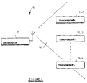
- An electronic identification system is generally designated 10 in figure 1.
- the system includes a radio frequency (RF) interrogator or reader 12 and a plurality of associated passive transponders, transponder #1 to transponder #n designated 14.1 to 14.n.
- RF radio frequency
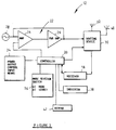
- the interrogator 12 in use, and when in a read mode, transmits via transmitter stage 22 (shown in figure 2) a RF interrogation signal, thereby creating an energizing field 16.
- the transponders in the field are energized by the signal and each transponder back-scatter modulates the signal with identification code data characteristic of that transponder.
- the interrogator 12 includes a receiver stage 18 for receiving the back-scatter modulated signal and the controller 20 reads the identification code data. The interrogator then transmits an acknowledgement signal which is received by the transponder just read. That transponder is then disabled and it ceases to respond to the interrogation signal.
- the interrogator also includes a carrier signal generator in the form of oscillator 28 and transmitter stage 22 including a variable gain amplifier 24 and a power amplifier 26. Routing device 30, under control of controller 20, connects either the transmitter stage 22 or the receiver stage 18 to read antenna 32 alternatively directional antenna 40, as hereinafter described.
- An important feature of the interrogator 12 is that the reading range thereof is adjustable, more particularly by adjusting the output power of an energizing signal transmitted thereby.
- the power may be adjusted by varying the amplitude of the energizing signal and/or the duty cycle of pulses in the interrogation signal.
- a user manipulatable output power control input knob 34 is connected to controller 20.
- the controller 20 generates a reference voltage, which is dependent on the position of the knob. This reference voltage is provided as one input of a variable gain amplifier 24.
- the other input is connected to a feed-back loop also connected to the output of power amplifier 26.
- the output power level is thus manually adjustable by a user, by manipulating input knob 34.
- variable output power level is schematically shown in figure 3.
- the knob on a first setting power Pm 1 is transmitted so that the interrogator has a first range
- power Pm 2 is transmitted so that the interrogator has a second range
- power Pm 3 is transmitted, wherein Pm 3 > Pm 2 > Pm 1.
- the third range is larger than the second, which is larger than the first.
- transponders 14.1 to 14.3 receive sufficient energy from the interrogator to respond to the signal.
- transponders 14.1 to 14.8 receive sufficient energy.
- transponders 14.1 to 14.15 receive sufficient energy.
- the user may first switch the knob to the aforementioned first setting to transmit power Pm 1 . Since there are only three transponders responding, less collisions and corruption of data will occur, which should result in a faster time to read all three transponders. As each of transponders 14.1 to 14.3 is read sequentially, the interrogator transmits an acknowledgement signal to the relevant transponder, to cause it to switch to a sleep mode wherein it is disabled and no longer responds to the energizing signal. Thereafter, the knob is set on the second setting.
- transponders 14.1 to 14.3 are in the sleep mode, only transponders 14.4 to 14.8 would respond, which again should result in faster reading times.
- the knob is set to the third setting and since transponders 14.1 to 14.8 are now in the sleep mode, transponders 14.9 to 14.15 only respond. Again faster reading times may be achieved, which may also result in a faster system reading time for reading all the transponders.
- the controller 20 may be sensitive to the number and/or rate of transponders read and may be configured automatically to increase or decrease the power level (thereby to increase or decrease the number of transponders being energized at a time) in accordance with a program, to optimize the speed of reading a plurality of transponders.
- the power may be varied continuously or in step-wise manner.
- a method of searching and finding a selected transponder Ts amongst a plurality of transponders T 1 to T n distributed in a large storage volume 50 is illustrated in figure 5.
- This method is performed by switching the mode selection switch 36 (shown in figure 2) to a search mode.
- directional antenna 40 is connected to the routing device 30.
- the interrogator 12 does not transmit the acknowledgement signal after reception and successful reading of a transponder identification code, as is the case in the aforementioned read mode.
- the user moves closer to the transponder (as shown in dotted lines in figure 5) and progressively decreases the output power by manipulating knob 34.
- the bleeper 38 indicates that the transponder to be found remains in the energizing field, the size of which progressively decreases, as shown at E 1 and E 2 respectively.
Landscapes
- Engineering & Computer Science (AREA)
- Physics & Mathematics (AREA)
- Toxicology (AREA)
- Artificial Intelligence (AREA)
- Computer Vision & Pattern Recognition (AREA)
- General Physics & Mathematics (AREA)
- Theoretical Computer Science (AREA)
- Health & Medical Sciences (AREA)
- Computer Networks & Wireless Communication (AREA)
- Electromagnetism (AREA)
- General Health & Medical Sciences (AREA)
- Radar Systems Or Details Thereof (AREA)
- Near-Field Transmission Systems (AREA)
Applications Claiming Priority (2)
| Application Number | Priority Date | Filing Date | Title |
|---|---|---|---|
| ZA9802235 | 1998-03-17 | ||
| ZA982235 | 1998-03-17 |
Publications (2)
| Publication Number | Publication Date |
|---|---|
| EP0944015A2 true EP0944015A2 (de) | 1999-09-22 |
| EP0944015A3 EP0944015A3 (de) | 2000-03-01 |
Family
ID=25586902
Family Applications (1)
| Application Number | Title | Priority Date | Filing Date |
|---|---|---|---|
| EP99302043A Withdrawn EP0944015A3 (de) | 1998-03-17 | 1999-03-17 | Abfragegerät mit veränderlicher Maximal-Ausgangsleistung |
Country Status (2)
| Country | Link |
|---|---|
| EP (1) | EP0944015A3 (de) |
| JP (1) | JPH11344562A (de) |
Cited By (11)
| Publication number | Priority date | Publication date | Assignee | Title |
|---|---|---|---|---|
| WO2007018840A2 (en) | 2005-07-20 | 2007-02-15 | Intelleflex Corporation | Ramped interrogation power levels |
| WO2008031563A1 (de) * | 2006-09-12 | 2008-03-20 | Wanzl Metallwarenfabrik Gmbh | Einkaufswagen |
| EP1869903A4 (de) * | 2005-02-10 | 2009-03-11 | Datalogic Mobile Inc | Rfid-tag-singulierung |
| WO2009042430A2 (en) | 2007-09-25 | 2009-04-02 | Symbol Technologies, Inc. | Optimizing rfid reader duty cycle or power to preserve battery life |
| EP1527616A4 (de) * | 2002-08-09 | 2009-05-13 | Sensormatic Electronics Corp | Gepulstes leistungsversorgungsverfahren mit vergrössertem lesebereich für ein rfid-lesegerät |
| US7602293B2 (en) | 2004-06-15 | 2009-10-13 | Brother Kogyo Kabushiki Kaisha | Interrogator for RFID tag |
| EP1864387A4 (de) * | 2005-03-30 | 2010-04-28 | Samsung Electronics Co Ltd | Mobilfunkfrequenz-identifikationsleser, tragbares endgerät damit und hf-sendeleistungseinstellverfahren dafür |
| EP1743271A4 (de) * | 2004-03-05 | 2010-10-27 | Seknion Inc | Verfahren und vorrichtung zur verbesserung der leistung und genauigkeit von rfid-systemen |
| US7969283B2 (en) | 2003-11-25 | 2011-06-28 | Brother Kogyo Kabushiki Kaisha | RFID tag information communicating device |
| RU2497147C2 (ru) * | 2011-11-18 | 2013-10-27 | Открытое акционерное общество "Авангард" | Способ обнаружения и идентификации разыскиваемых транспондеров из множества пассивных транспондеров и система для его осуществления |
| CN109314546A (zh) * | 2016-06-24 | 2019-02-05 | 三菱电机株式会社 | 无线通信装置以及无线通信方法 |
Families Citing this family (9)
| Publication number | Priority date | Publication date | Assignee | Title |
|---|---|---|---|---|
| US6756880B2 (en) * | 2002-03-21 | 2004-06-29 | Rf Saw Component Incorporated | Reader and response control system for discrimination between multiple surface acoustic wave identification tags and method of operation thereof |
| JP2006033143A (ja) * | 2004-07-13 | 2006-02-02 | Sharp Corp | 無線識別デバイスと無線識別デバイス処理装置 |
| JPWO2006061890A1 (ja) * | 2004-12-08 | 2008-06-05 | 富士通株式会社 | タグ情報選択方法、電子装置及びプログラム |
| JP2006309592A (ja) * | 2005-04-28 | 2006-11-09 | Ntt Advanced Technology Corp | 無線タグおよびその近接状態検出方法 |
| WO2007034543A1 (ja) * | 2005-09-21 | 2007-03-29 | Matsushita Electric Industrial Co., Ltd. | タグ読み取り装置 |
| JP2009070035A (ja) * | 2007-09-12 | 2009-04-02 | Brother Ind Ltd | 無線タグ通信装置 |
| JP4983505B2 (ja) * | 2007-09-25 | 2012-07-25 | ブラザー工業株式会社 | 無線タグ通信装置 |
| JP5164816B2 (ja) * | 2008-12-05 | 2013-03-21 | 東芝テック株式会社 | 無線タグ読取装置及び無線タグ認識方法 |
| JP2011237941A (ja) * | 2010-05-07 | 2011-11-24 | Toshiba Tec Corp | 無線タグ通信装置及びこの装置を用いた無線タグ探索方法 |
Family Cites Families (4)
| Publication number | Priority date | Publication date | Assignee | Title |
|---|---|---|---|---|
| ATE110480T1 (de) * | 1987-03-31 | 1994-09-15 | Identec Ltd | Zugangskontrolleinrichtung. |
| US5294931A (en) * | 1992-04-29 | 1994-03-15 | Texas Instruments Deutschland Gmbh | Method of interrogating a plurality of transponders arranged in the transmission range of an interrogating device and transponders for use in the said method |
| US5500651A (en) * | 1994-06-24 | 1996-03-19 | Texas Instruments Incorporated | System and method for reading multiple RF-ID transponders |
| US5777561A (en) * | 1996-09-30 | 1998-07-07 | International Business Machines Corporation | Method of grouping RF transponders |
-
1999
- 1999-03-17 JP JP11072601A patent/JPH11344562A/ja active Pending
- 1999-03-17 EP EP99302043A patent/EP0944015A3/de not_active Withdrawn
Cited By (16)
| Publication number | Priority date | Publication date | Assignee | Title |
|---|---|---|---|---|
| EP1527616A4 (de) * | 2002-08-09 | 2009-05-13 | Sensormatic Electronics Corp | Gepulstes leistungsversorgungsverfahren mit vergrössertem lesebereich für ein rfid-lesegerät |
| US7969283B2 (en) | 2003-11-25 | 2011-06-28 | Brother Kogyo Kabushiki Kaisha | RFID tag information communicating device |
| EP1743271A4 (de) * | 2004-03-05 | 2010-10-27 | Seknion Inc | Verfahren und vorrichtung zur verbesserung der leistung und genauigkeit von rfid-systemen |
| US7602293B2 (en) | 2004-06-15 | 2009-10-13 | Brother Kogyo Kabushiki Kaisha | Interrogator for RFID tag |
| EP1869903A4 (de) * | 2005-02-10 | 2009-03-11 | Datalogic Mobile Inc | Rfid-tag-singulierung |
| EP1864387A4 (de) * | 2005-03-30 | 2010-04-28 | Samsung Electronics Co Ltd | Mobilfunkfrequenz-identifikationsleser, tragbares endgerät damit und hf-sendeleistungseinstellverfahren dafür |
| WO2007018840A3 (en) * | 2005-07-20 | 2007-06-07 | Intelleflex Corp | Ramped interrogation power levels |
| US8872633B2 (en) | 2005-07-20 | 2014-10-28 | Intelleflex Corporation | Ramped interrogation power levels |
| WO2007018840A2 (en) | 2005-07-20 | 2007-02-15 | Intelleflex Corporation | Ramped interrogation power levels |
| WO2008031563A1 (de) * | 2006-09-12 | 2008-03-20 | Wanzl Metallwarenfabrik Gmbh | Einkaufswagen |
| WO2009042430A3 (en) * | 2007-09-25 | 2010-07-22 | Symbol Technologies, Inc. | Optimizing rfid reader duty cycle or power to preserve battery life |
| US7825806B2 (en) | 2007-09-25 | 2010-11-02 | Symbol Technologies, Inc. | Optimizing RFID reader duty cycle or power to preserve battery life |
| CN101809588B (zh) * | 2007-09-25 | 2014-03-26 | 符号技术有限公司 | 优化rfid阅读器占空比或者功率以保存电池寿命 |
| WO2009042430A2 (en) | 2007-09-25 | 2009-04-02 | Symbol Technologies, Inc. | Optimizing rfid reader duty cycle or power to preserve battery life |
| RU2497147C2 (ru) * | 2011-11-18 | 2013-10-27 | Открытое акционерное общество "Авангард" | Способ обнаружения и идентификации разыскиваемых транспондеров из множества пассивных транспондеров и система для его осуществления |
| CN109314546A (zh) * | 2016-06-24 | 2019-02-05 | 三菱电机株式会社 | 无线通信装置以及无线通信方法 |
Also Published As
| Publication number | Publication date |
|---|---|
| JPH11344562A (ja) | 1999-12-14 |
| EP0944015A3 (de) | 2000-03-01 |
Similar Documents
| Publication | Publication Date | Title |
|---|---|---|
| EP0944015A2 (de) | Abfragegerät mit veränderlicher Maximal-Ausgangsleistung | |
| US7176784B2 (en) | Multi-mode radio frequency device | |
| US5995019A (en) | Method for communicating with RF transponders | |
| US5036308A (en) | Identification system | |
| EP1001366B1 (de) | Elektronisches Identifizierungssystem | |
| EP0420180B1 (de) | Antwortgerät für Fahrzeugerkennungseinrichtung | |
| US6486769B1 (en) | Method and system for automatic adjustment and diagnosis of radio frequency identification systems using programmable checktags | |
| AU764975B2 (en) | Identification system | |
| US5940006A (en) | Enhanced uplink modulated backscatter system | |
| EP0694860B1 (de) | Vorrichtung und Verfahren zur Identifizierung mehrerer Transponder | |
| US5491715A (en) | Automatic antenna tuning method and circuit | |
| US20060176152A1 (en) | RFID power ramping for tag singulation | |
| EP0768540A1 (de) | Transponderverfahren und -system | |
| US20060273882A1 (en) | RFID tag with separate transmit and receive clocks and related method | |
| US6731199B1 (en) | Non-contact communication system | |
| US8077010B2 (en) | RFID interrogator device | |
| EP3182608A1 (de) | Dynamische sendersignalhüllkurvenformgebungssteuerung für nfc- oder rfid-vorrichtungen | |
| WO2002073525A1 (en) | Multi-level rf identification system | |
| EP1277163A2 (de) | Rfid-leser ausgangsteuerungsvorrichtung und -verfahren | |
| AU2001253769A1 (en) | RFID reader output control apparatus and method | |
| US20080042803A1 (en) | Adjusting signal strength used to detect tags | |
| KR101239131B1 (ko) | 무선주파수인식 리더 및 그것의 이득 제어 방법 | |
| JP2008160312A (ja) | 無線通信装置 | |
| JP2736830B2 (ja) | データ伝送装置およびこれに用いられる質問装置 | |
| EP2620895B1 (de) | System zur Verwaltung von RFID-Tags |
Legal Events
| Date | Code | Title | Description |
|---|---|---|---|
| PUAI | Public reference made under article 153(3) epc to a published international application that has entered the european phase |
Free format text: ORIGINAL CODE: 0009012 |
|
| AK | Designated contracting states |
Kind code of ref document: A2 Designated state(s): AT BE CH DE ES FR GB IT LI NL |
|
| AX | Request for extension of the european patent |
Free format text: AL;LT;LV;MK;RO;SI |
|
| RIN1 | Information on inventor provided before grant (corrected) |
Inventor name: KRUGER, JOHAN DAWID Inventor name: TURNER, CHRISTOPHER GORDON GERVASE |
|
| PUAL | Search report despatched |
Free format text: ORIGINAL CODE: 0009013 |
|
| AK | Designated contracting states |
Kind code of ref document: A3 Designated state(s): AT BE CH CY DE DK ES FI FR GB GR IE IT LI LU MC NL PT SE |
|
| AX | Request for extension of the european patent |
Free format text: AL;LT;LV;MK;RO;SI |
|
| 17P | Request for examination filed |
Effective date: 20000818 |
|
| AKX | Designation fees paid |
Free format text: AT BE CH DE ES FR GB IT LI NL |
|
| STAA | Information on the status of an ep patent application or granted ep patent |
Free format text: STATUS: THE APPLICATION HAS BEEN WITHDRAWN |
|
| 18W | Application withdrawn |
Withdrawal date: 20021030 |