EP0944121A1 - Dispositif d'enlèvement/de fixation à utiliser dans un dispositif électronique compact - Google Patents
Dispositif d'enlèvement/de fixation à utiliser dans un dispositif électronique compact Download PDFInfo
- Publication number
- EP0944121A1 EP0944121A1 EP99200836A EP99200836A EP0944121A1 EP 0944121 A1 EP0944121 A1 EP 0944121A1 EP 99200836 A EP99200836 A EP 99200836A EP 99200836 A EP99200836 A EP 99200836A EP 0944121 A1 EP0944121 A1 EP 0944121A1
- Authority
- EP
- European Patent Office
- Prior art keywords
- lock
- slider
- electronic device
- release button
- removal
- Prior art date
- Legal status (The legal status is an assumption and is not a legal conclusion. Google has not performed a legal analysis and makes no representation as to the accuracy of the status listed.)
- Withdrawn
Links
Images


Classifications
-
- H—ELECTRICITY
- H01—ELECTRIC ELEMENTS
- H01M—PROCESSES OR MEANS, e.g. BATTERIES, FOR THE DIRECT CONVERSION OF CHEMICAL ENERGY INTO ELECTRICAL ENERGY
- H01M50/00—Constructional details or processes of manufacture of the non-active parts of electrochemical cells other than fuel cells, e.g. hybrid cells
- H01M50/20—Mountings; Secondary casings or frames; Racks, modules or packs; Suspension devices; Shock absorbers; Transport or carrying devices; Holders
-
- G—PHYSICS
- G11—INFORMATION STORAGE
- G11B—INFORMATION STORAGE BASED ON RELATIVE MOVEMENT BETWEEN RECORD CARRIER AND TRANSDUCER
- G11B31/00—Arrangements for the associated working of recording or reproducing apparatus with related apparatus
-
- G—PHYSICS
- G11—INFORMATION STORAGE
- G11B—INFORMATION STORAGE BASED ON RELATIVE MOVEMENT BETWEEN RECORD CARRIER AND TRANSDUCER
- G11B33/00—Constructional parts, details or accessories not provided for in the other groups of this subclass
- G11B33/12—Disposition of constructional parts in the apparatus, e.g. of power supply, of modules
- G11B33/121—Disposition of constructional parts in the apparatus, e.g. of power supply, of modules the apparatus comprising a single recording/reproducing device
- G11B33/123—Mounting arrangements of constructional parts onto a chassis
- G11B33/124—Mounting arrangements of constructional parts onto a chassis of the single recording/reproducing device, e.g. disk drive, onto a chassis
-
- Y—GENERAL TAGGING OF NEW TECHNOLOGICAL DEVELOPMENTS; GENERAL TAGGING OF CROSS-SECTIONAL TECHNOLOGIES SPANNING OVER SEVERAL SECTIONS OF THE IPC; TECHNICAL SUBJECTS COVERED BY FORMER USPC CROSS-REFERENCE ART COLLECTIONS [XRACs] AND DIGESTS
- Y02—TECHNOLOGIES OR APPLICATIONS FOR MITIGATION OR ADAPTATION AGAINST CLIMATE CHANGE
- Y02E—REDUCTION OF GREENHOUSE GAS [GHG] EMISSIONS, RELATED TO ENERGY GENERATION, TRANSMISSION OR DISTRIBUTION
- Y02E60/00—Enabling technologies; Technologies with a potential or indirect contribution to GHG emissions mitigation
- Y02E60/10—Energy storage using batteries
Definitions
- the present invention relates to a removal/attachment device for use with a compact electronic device which permits removable attachment of a compact electronic device, such as a battery, to an electronic device main unit; e.g., which permits removable attachment of a battery to a battery holder of an electronic camera or a video camera or removable attachment of an electronic camera and a video camera to a player.
- a compact electronic device such as a battery
- an electronic device main unit e.g., which permits removable attachment of a battery to a battery holder of an electronic camera or a video camera or removable attachment of an electronic camera and a video camera to a player.
- a compact electronic device e.g., a battery 10
- a battery 10 is attached to, e.g., a battery holder 11
- the battery 10 is fitted from above to a battery attachment section 15 of the battery holder 11.
- the bottom of the battery 10 presses a sensor pin 17, and lock recesses 14 formed in the battery 10 engage fixed hooks 16 of the battery holder 11.
- the battery holder 11 comprises an upper case 12 and a lower case 13.
- a lock arm 28 pivots around a pin 30, which serves as a fulcrum, by the force of a spring 57, and an engagement recess 31 engages a lock pin 34 of a pivotal arm 32.
- a slidable member 37 is slid along a slit 23 against the restoration force of a coil spring 27 through use of an operation knob 18 in the foregoing state, the pivotal arm 32 pivots around a pin 33, because the slidable member 37 and the pivotal arm 32 are connected together by means of a pin 36 and an elongated hole 35.
- a lock section (not shown) which is provided in the area of the lock button 19 facing the upper case 12 engages a lock rib 22 and comes to stop, because the lock button 19 is rotatively forced by means of a pin 20 and a spring 21.
- the battery 10 is connected to an unillustrated terminal provided on the battery holder 11.
- the compact electronic device 10 is an electronic camera
- the electronic camera is connected to a connector which is actuated in association with the slider 24.
- the user presses the projecting edge of the operation knob 18 against the restoration force of the spring 21.
- the lock button 19 is then pivoted around the pin 20, the unillustrated internal lock section is disengaged from the lock rib 22, and the coil spring 27 brings the slidable member 37 and the pivotal arm 38 to their original positions.
- the slider 24 is brought into its original position by means of the coil spring 59.
- the fixed hooks 16 are disengaged from the lock recesses 14, and the battery 10 can be removed from the battery attachment section 15 of the battery holder 11.
- the conventional removal/attachment device having the foregoing configuration requires a considerably large number of parts. More specifically, even in the case of the illustrated example, sliding the slider 24 requires four springs, i.e., the spring 21, the coil spring 27, the spring 57, and the coil spring 59. More smooth movement of the slider entails an increase in the number of springs. Further, at least more than ten screws and pins are required by the conventional device, and many complicated components, such as the lock arm 28, the pivotal arm 32, and the operation knob 18, are also used in the device.
- the object of the present invention is to provide a removal/attachment device which requires fewer parts and enables reliable locking and simple removal of a compact electronic device.
- a removal/attachment device which removably holds a compact electronic device on an electronic device main unit by means of fixed hooks and lock recesses and which includes a slider that is movably attached to the electronic device main unit and a lock release button provided so as to be movable in a direction crossing the direction in which the slider travels, the removal/attachment device comprising:
- the lock release button fits into a through hole of the operation knob so as to be able to advance or recede, and the spring section is formed from an S-shaped molded spring.
- the electronic device main unit comprises an upper case and a lower case, and the slider and the lock release button are housed while the upper case and the lower case are fitted together. Between the upper and lower cases is provided a guide pin which doubles as a guide for guiding the movement of the slider while fitting into an elongated hole and as a rib for connecting together the upper and lower cases.
- the user presses the lock release button is pressed against the restoration force of the spring section, thereby disengaging the lock pawl from the lock protuberance.
- the lock release button is pressed against the restoration force of the spring section, thereby disengaging the lock pawl from the lock protuberance.
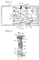
- FIGs. 1 through 5 A preferred embodiment will be described by reference to FIGs. 1 through 5.
- reference numeral 10 designates a compact electronic device.
- a removably attachable battery is taken as an example of the compact electronic device 10.
- a pair of lock recesses 14 are integrally formed on each side of the bottom surface of the battery 10. If the compact electronic device 10 corresponds to a camera, a tripod screw hole 40 is formed in the bottom of the device.
- reference numeral 11 designates an electronic device main unit.
- a battery holder which permits removable attachment of the battery 10 is taken as an example of the electronic device main unit 11.
- the battery holder 11 is formed by assembling the upper case 12 and the lower case 13 and superimposing one on the other.
- a battery 46 is further removably attached to the lower case 13.
- the electronic device main unit 11 corresponds to so-called a double battery and is integrally attached to the end of an electronic camera or a video camera.
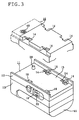
- a pair of fixed hook travel holes 54 are formed in, and along each side of, a battery attachment section 15 of the battery holder 11 which serves as a compact electronic device attachment section, in such a way as to correspond to the lock recesses 14.
- the internal fixed hooks 16 protrude from the fixed hook travel holes 54.
- a positioning pin 39 is formed in the battery attachment section 15 for the purpose of positioning the compact electronic device 10 by utilization of the tripod screw hole 40.
- the operation knob 18 for sliding the slider 24, which will be described later, is provided in the outer surface on each side of the battery holder 11, and the lock release button 38 is fitted to the knob 18.
- FIG. 4 is an exploded perspective view showing the inside of the electronic device main unit, or the battery holder, 11 while the upper case 12 shown in FIG. 3 is removed.
- Reference numeral 24 provided in FIG. 4 designates a slider, and the lock release button 38 is fitted into the slider 24 from the bottom surface side thereof.
- a pair of fixed hooks 16 are formed on each side of the slider 24 so as to protrude upward.
- the operation knob 18 is provided on a side plate 60 on each side of the slider 24, and a through hole 56?along which the lock release button 38 to be described later travels back and forth?is formed in one of the operation knobs 18.
- An elongated guide hole 25 is formed in the plane portion of the slider 24 in the vicinity of each of the four corners of the slider.
- a lock claw clearance hole 43 In the center of the plane portion of the slider 24 are formed a lock claw clearance hole 43 and a coil spring attachment elongated hole 45.
- a click spring 44 notched into a rectangular C-shaped form is formed in the vicinity of the center of the plane portion.
- an engagement section 51 to which a coil spring 55 fits is integrally formed with the coil spring attachment elongated hole 45.
- the lock release button 38 loosely fits into and travels back and forth along the through hole 56 of the operation knob 18.
- Two S-shaped springs 41 are integrally formed with the end of the lock release button 38 by means of molding.
- the open ends of the springs 41 are connected together by means of a spring end section 47, and a lock claw 42 having a tapered portion and a lock portion is integrally formed on the upper surface of the lock release button 38.
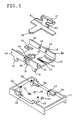
- FIG. 5 shows the upper case 12 shown in FIG. 3 and the slider 24 and the lock release button 38 shown in FIG. 4 while they are turned upside down.
- Lock claws 48 to which is fixed the spring end section 47 are formed integrally with the interior side of one of the side plates 60.
- the slider 24 is as previously described in connection with FIG. 4.
- the fixed hook travel holes 54 that have been described in connection with FIG. 3 are formed in the vicinity of the four respective corners of the upper case 12.
- the guide pins 53 that loosely fit into the elongated holes 25 of the slider 24 and guide the sliding action of the slider 24 are integrally formed with the upper case 12 in the vicinity of the fixed hook travel holes 54.
- the guide pins 53 double as assembly ribs for integrally connecting together the upper and lower cases 12 and 13 shown in FIG. 4.
- a coil spring receiving protuberance 50 which loosely fits into the coil spring attachment elongated hole 45 of the slider 24 and which fixedly holds the other end of the coil spring 55; a lock protuberance 49 which loosely fits into the lock claw clearance hole 43 of the slider 24 and engages or disengages from the lock claw 42 of the lock release button 38; and the click protuberance 52 which faces the click spring 44 of the slider 24.
- the fixed hooks 16 of the slider 24 are loosely fitted into the fixed hook travel holes 54 of the upper case 12, and the coil spring receiving protuberance 50 is fitted into the coil spring attachment elongated hole 45.
- the lock protuberance 49 is fitted into the lock claw clearance hole 43.
- one end of the coil spring 55 is fitted into the spring engagement section 51, and the other end of the coil spring 55 is fixed to the coil spring receiving protuberance 50.
- the lock release button 38 is fitted into the through hole 56 of the slider 24 from the inside, and the spring end section 47 is engaged with the lock claw 48 while the spring sections 41 are compressed.
- FIG. 3 shows the thus-assembled battery holder 11 while it is turned upside down.
- the battery 10 is fitted to the battery attachment section 15 of the thus-assembled battery holder 11 from above, so that the fixed hooks 16 are loosely fitted into the lock recesses 14 of the battery 10.
- the slider 24 slides integrally along with the lock release button 38, whereby the fixed hooks 16 are engaged with the lock recesses 15 of the battery 10.
- the lock claw 42 integrally formed with the lock release button 38 also travels; however, the movement of the lock claw 42 is hindered by the lock protuberance 49.
- the lock protuberance 49 and the lock claw 42 respectively have tapered portions, and the spring sections 41 are integrally formed with the lock release button 38.
- the user presses the lock release button 38 into the through hole 56 against the restoration force of the spring sections 41.
- the lock claw 42 integrated with the lock release button 38 is disengaged from the lock protuberance 49, and the lock release button 38 is slid in the direction opposite that in which it had been slid, together with the operation knobs 18, which are held in a pressed state.
- the fixed hooks 16 integrally formed with the slider 24 can be disengaged from the lock recesses 14, thus enabling the battery 10 to be removed from the battery holder 11.
- the compact electronic device 10 may correspond to an electronic camera or a video camera
- the electronic device main unit 11 may correspond to a player.
- the present invention may apply to the compact electronic device 10 and the overall accessories thereof.
- a removal/attachment device which includes a slider movably attached to an electronic device main unit and a lock release button provided so as to be movable in the direction crossing the direction in which a slider travels, the removal/attachment device comprising:
- the lock release button fits into a through hole of the operation knob so as to be able to advance or recede
- the spring section is formed from an S-shaped molded spring and hence can withstand the forward and backward movement of the lock release button for a long period of time.
- the electronic device main unit comprises an upper case and a lower case, and the slider and the lock release button are housed while the upper case and the lower case are fitted together.
- a guide pin which doubles as a guide for guiding the movement of the slider while fitting into an elongated hole and as a rib for connecting together the upper and lower cases.
Landscapes
- Chemical & Material Sciences (AREA)
- Chemical Kinetics & Catalysis (AREA)
- Electrochemistry (AREA)
- General Chemical & Material Sciences (AREA)
- Battery Mounting, Suspending (AREA)
- Studio Devices (AREA)
- Mounting Components In General For Electric Apparatus (AREA)
Applications Claiming Priority (2)
| Application Number | Priority Date | Filing Date | Title |
|---|---|---|---|
| JP8954498 | 1998-03-19 | ||
| JP10089544A JPH11274758A (ja) | 1998-03-19 | 1998-03-19 | 小型電子機器の着脱装置 |
Publications (1)
| Publication Number | Publication Date |
|---|---|
| EP0944121A1 true EP0944121A1 (fr) | 1999-09-22 |
Family
ID=13973767
Family Applications (1)
| Application Number | Title | Priority Date | Filing Date |
|---|---|---|---|
| EP99200836A Withdrawn EP0944121A1 (fr) | 1998-03-19 | 1999-03-18 | Dispositif d'enlèvement/de fixation à utiliser dans un dispositif électronique compact |
Country Status (2)
| Country | Link |
|---|---|
| EP (1) | EP0944121A1 (fr) |
| JP (1) | JPH11274758A (fr) |
Cited By (4)
| Publication number | Priority date | Publication date | Assignee | Title |
|---|---|---|---|---|
| CN101345091B (zh) * | 2007-07-13 | 2012-09-05 | Ge医疗系统环球技术有限公司 | 固定/释放机构及利用该固定/释放机构的基座 |
| US9030818B2 (en) | 2012-09-28 | 2015-05-12 | Fujitsu Limited | Electronic device and elastic slide lock member |
| TWI885820B (zh) * | 2023-05-30 | 2025-06-01 | 四零四科技股份有限公司 | 背板總成套件、相關的可拆卸總成套件及相關的電子裝置 |
| US12526946B2 (en) | 2023-05-30 | 2026-01-13 | Moxa Inc. | Rail mounting backplane assembly kit and related rail mounting electronic device |
Families Citing this family (3)
| Publication number | Priority date | Publication date | Assignee | Title |
|---|---|---|---|---|
| CN201000906Y (zh) | 2007-01-26 | 2008-01-02 | 深圳迈瑞生物医疗电子股份有限公司 | 电池组件及其固定结构 |
| JP5673517B2 (ja) * | 2011-12-14 | 2015-02-18 | アイコム株式会社 | 電子機器の筐体構造 |
| JP5730242B2 (ja) | 2012-06-05 | 2015-06-03 | 三菱電機株式会社 | 照明装置及び誘導灯 |
Citations (2)
| Publication number | Priority date | Publication date | Assignee | Title |
|---|---|---|---|---|
| EP0592090A1 (fr) * | 1992-09-16 | 1994-04-13 | International Business Machines Corporation | Mécanisme de sécurité pour ordinateur portable |
| EP0707350A1 (fr) * | 1994-09-02 | 1996-04-17 | Sony Corporation | Batterie et dispositif de chargement de celle-ci |
-
1998
- 1998-03-19 JP JP10089544A patent/JPH11274758A/ja active Pending
-
1999
- 1999-03-18 EP EP99200836A patent/EP0944121A1/fr not_active Withdrawn
Patent Citations (2)
| Publication number | Priority date | Publication date | Assignee | Title |
|---|---|---|---|---|
| EP0592090A1 (fr) * | 1992-09-16 | 1994-04-13 | International Business Machines Corporation | Mécanisme de sécurité pour ordinateur portable |
| EP0707350A1 (fr) * | 1994-09-02 | 1996-04-17 | Sony Corporation | Batterie et dispositif de chargement de celle-ci |
Cited By (5)
| Publication number | Priority date | Publication date | Assignee | Title |
|---|---|---|---|---|
| CN101345091B (zh) * | 2007-07-13 | 2012-09-05 | Ge医疗系统环球技术有限公司 | 固定/释放机构及利用该固定/释放机构的基座 |
| US9030818B2 (en) | 2012-09-28 | 2015-05-12 | Fujitsu Limited | Electronic device and elastic slide lock member |
| TWI885820B (zh) * | 2023-05-30 | 2025-06-01 | 四零四科技股份有限公司 | 背板總成套件、相關的可拆卸總成套件及相關的電子裝置 |
| US12526946B2 (en) | 2023-05-30 | 2026-01-13 | Moxa Inc. | Rail mounting backplane assembly kit and related rail mounting electronic device |
| US12621947B2 (en) | 2023-05-30 | 2026-05-05 | Moxa Inc. | Backplane assembly kit, related detachable assembly kit and related electronic device |
Also Published As
| Publication number | Publication date |
|---|---|
| JPH11274758A (ja) | 1999-10-08 |
Similar Documents
| Publication | Publication Date | Title |
|---|---|---|
| US6490436B1 (en) | Battery pack removing device | |
| JP2785750B2 (ja) | 電子機器カバーのロック構造 | |
| JPH11274751A (ja) | 小型電子機器の着脱装置 | |
| JPH11274758A (ja) | 小型電子機器の着脱装置 | |
| JP3716457B2 (ja) | 操作ボタン装置 | |
| JPH0571834U (ja) | カメラの電池蓋構造 | |
| JPH0612582Y2 (ja) | スイッチ装置 | |
| JP2569598Y2 (ja) | 電池蓋構造 | |
| CN220290987U (zh) | 遥控器的外壳及遥控器 | |
| JP3637816B2 (ja) | 電気情報機器 | |
| EP1602970A2 (fr) | Caméra | |
| JPH0346441Y2 (fr) | ||
| JP2545883Y2 (ja) | 電池蓋構造 | |
| JPH0520445U (ja) | 携帯電話機用車載アダプターのロツク機構 | |
| JP2786134B2 (ja) | 電池パック固定部の構造 | |
| JP2920067B2 (ja) | スイッチ | |
| JP4071216B2 (ja) | 電子機器 | |
| JP2511520Y2 (ja) | 電気かみそり | |
| JPH0331104Y2 (fr) | ||
| JPH0537619A (ja) | 小型電子機器の保持装置 | |
| JP2595710Y2 (ja) | スライドスイッチ操作装置 | |
| JP3331454B2 (ja) | 回転式電子部品用シャフトのロック又はクリック機構 | |
| JPH05160757A (ja) | 電子機器 | |
| JPS6327478Y2 (fr) | ||
| JPH0422060A (ja) | 取付け部品の着脱機構 |
Legal Events
| Date | Code | Title | Description |
|---|---|---|---|
| PUAI | Public reference made under article 153(3) epc to a published international application that has entered the european phase |
Free format text: ORIGINAL CODE: 0009012 |
|
| AK | Designated contracting states |
Kind code of ref document: A1 Designated state(s): DE FR |
|
| AX | Request for extension of the european patent |
Free format text: AL;LT;LV;MK;RO;SI |
|
| RTI1 | Title (correction) |
Free format text: REMOVAL/ATTACHMENT DEVICE FOR USE WITH COMPACT ELECTRONIC DEVICE |
|
| 17P | Request for examination filed |
Effective date: 20000119 |
|
| AKX | Designation fees paid |
Free format text: DE FR |
|
| 17Q | First examination report despatched |
Effective date: 20010226 |
|
| GRAH | Despatch of communication of intention to grant a patent |
Free format text: ORIGINAL CODE: EPIDOS IGRA |
|
| RTI1 | Title (correction) |
Free format text: SYSTEM COMPRISING A COMPACT ELECTRONIC DEVICE AND AN ELECTRONIC DEVICE MAIN UNIT REMOVABLY ATTACHABLE BY MEANS OF REMOV |
|
| STAA | Information on the status of an ep patent application or granted ep patent |
Free format text: STATUS: THE APPLICATION IS DEEMED TO BE WITHDRAWN |
|
| 18D | Application deemed to be withdrawn |
Effective date: 20031001 |