EP0944150B1 - Relais de Buchholz amélioré - Google Patents
Relais de Buchholz amélioré Download PDFInfo
- Publication number
- EP0944150B1 EP0944150B1 EP99104014A EP99104014A EP0944150B1 EP 0944150 B1 EP0944150 B1 EP 0944150B1 EP 99104014 A EP99104014 A EP 99104014A EP 99104014 A EP99104014 A EP 99104014A EP 0944150 B1 EP0944150 B1 EP 0944150B1
- Authority
- EP
- European Patent Office
- Prior art keywords
- relay
- oil
- frame
- flap device
- flap
- Prior art date
- Legal status (The legal status is an assumption and is not a legal conclusion. Google has not performed a legal analysis and makes no representation as to the accuracy of the status listed.)
- Expired - Lifetime
Links
- 208000034699 Vitreous floaters Diseases 0.000 claims abstract description 18
- 239000004033 plastic Substances 0.000 claims description 3
- 229920003023 plastic Polymers 0.000 claims description 3
- 238000003780 insertion Methods 0.000 claims description 2
- 230000037431 insertion Effects 0.000 claims description 2
- 238000004519 manufacturing process Methods 0.000 description 3
- 230000035945 sensitivity Effects 0.000 description 3
- 229910000838 Al alloy Inorganic materials 0.000 description 2
- 239000012212 insulator Substances 0.000 description 2
- 229910001369 Brass Inorganic materials 0.000 description 1
- 238000009825 accumulation Methods 0.000 description 1
- 239000010951 brass Substances 0.000 description 1
- 238000005266 casting Methods 0.000 description 1
- 238000000354 decomposition reaction Methods 0.000 description 1
- 230000000694 effects Effects 0.000 description 1
- 230000001771 impaired effect Effects 0.000 description 1
- 238000007689 inspection Methods 0.000 description 1
- 230000000670 limiting effect Effects 0.000 description 1
- 239000007788 liquid Substances 0.000 description 1
- 230000007257 malfunction Effects 0.000 description 1
- 238000013021 overheating Methods 0.000 description 1
- 230000011664 signaling Effects 0.000 description 1
- 239000007787 solid Substances 0.000 description 1
- 239000005341 toughened glass Substances 0.000 description 1
Images


Classifications
-
- H—ELECTRICITY
- H01—ELECTRIC ELEMENTS
- H01H—ELECTRIC SWITCHES; RELAYS; SELECTORS; EMERGENCY PROTECTIVE DEVICES
- H01H35/00—Switches operated by change of a physical condition
- H01H35/24—Switches operated by change of fluid pressure, by fluid pressure waves, or by change of fluid flow
- H01H35/40—Switches operated by change of fluid pressure, by fluid pressure waves, or by change of fluid flow actuated by devices allowing continual flow of fluid, e.g. vane
- H01H35/405—Switches operated by change of fluid pressure, by fluid pressure waves, or by change of fluid flow actuated by devices allowing continual flow of fluid, e.g. vane the switch being of the reed switch type
-
- H—ELECTRICITY
- H01—ELECTRIC ELEMENTS
- H01H—ELECTRIC SWITCHES; RELAYS; SELECTORS; EMERGENCY PROTECTIVE DEVICES
- H01H33/00—High-tension or heavy-current switches with arc-extinguishing or arc-preventing means
- H01H33/02—Details
- H01H33/53—Cases; Reservoirs, tanks, piping or valves, for arc-extinguishing fluid; Accessories therefor, e.g. safety arrangements, pressure relief devices
- H01H33/55—Oil reservoirs or tanks; Lowering means therefor
- H01H33/555—Protective arrangements responsive to abnormal fluid pressure, liquid level or liquid displacement, e.g. Buchholz relays
-
- H—ELECTRICITY
- H01—ELECTRIC ELEMENTS
- H01H—ELECTRIC SWITCHES; RELAYS; SELECTORS; EMERGENCY PROTECTIVE DEVICES
- H01H35/00—Switches operated by change of a physical condition
- H01H35/24—Switches operated by change of fluid pressure, by fluid pressure waves, or by change of fluid flow
- H01H35/40—Switches operated by change of fluid pressure, by fluid pressure waves, or by change of fluid flow actuated by devices allowing continual flow of fluid, e.g. vane
-
- H—ELECTRICITY
- H01—ELECTRIC ELEMENTS
- H01H—ELECTRIC SWITCHES; RELAYS; SELECTORS; EMERGENCY PROTECTIVE DEVICES
- H01H36/00—Switches actuated by change of magnetic field or of electric field, e.g. by change of relative position of magnet and switch, by shielding
- H01H36/02—Switches actuated by change of magnetic field or of electric field, e.g. by change of relative position of magnet and switch, by shielding actuated by movement of a float carrying a magnet
Definitions
- the present invention relates to a Buchholz relay.
- the Buchholz relay must be applied at the highest point of the transformer and below the expansion vessel, which is commonly known as conservator, and must be filled with oil during normal operation.
- the gas can in fact, in a first case, originate from outside and be introduced through the circulation pumps or, as an alternative, it can be the result of the decomposition of the liquid or solid insulators caused by overheating or by the onset of electric arcs.
- the relay is usually constituted by a body obtained from aluminum alloy castings, inside which a supporting frame is placed for at least one movable device which comprises an upper floater and a lower floater for operating magnetic switches.
- the upper floater enables/disables an alarm circuit by means of the corresponding switch, while the lower floater operates a disconnection circuit in an equivalent manner.
- the Buchholz relay is provided with a suitably adjusted flap which is sensitive to the flow-rate of the oil current and is also connected to the circuit for disconnecting the transformer from the power supply.
- the flap is usually obtained monolithically with the lower floater, and when significant oil currents occur, the flap, by rotating about its own axis because it is directly affected by the flow, causes the intervention of the switch for closing the disconnection circuit.
- a possible particular characteristic is that the contact of the disconnection circuit is kept closed whenever the flap rotates under the action of intense oil currents or because the level of the oil has dropped below a certain value.
- the flap In order to reopen the contact, the flap must be returned to the normal position by means of a suitable pushbutton arranged on the cover of the relay.
- the flap must be adjusted appropriately so as to be sensitive to currents in excess of a certain preset limit.
- Said limit is usually set by standards or by the user, so that the manufacturer must produce different relays depending on the setting of the flap.
- the flap is adjusted by moving it appropriately along suitable guides or by using fixing screws, so as to reduce the surface of the flap that is affected by the oil currents.
- DE 3248275 A discloses a Buchholz relay having all the features of the preamble of claim 1.
- the aim of the present invention is to provide an improved Buchholz relay which solves the above drawbacks of conventional relays.
- an important object of the present invention is to provide a Buchholz relay which ensures good characteristics in terms of safety and most of all precision in the setting of the intervention threshold.
- Another important object of the present invention is to provide a Buchholz relay whose configuration is simpler than in conventional types.
- Another important object of the present invention is to provide a Buchholz relay whose assembly is simple with respect to conventional relays.
- Another object of the present invention is to provide a Buchholz relay which. without having to differentiate the production process allows end users to select the degree of sensitivity of intervention in the presence of oil currents.
- a Buchholz relay which comprises, to be immersed in an oil bath, a supporting frame for magnetic switches for closing circuits which are operated by movable devices, of which at least one is of the floater type and at least one is of the flap type rotatably associated with said frame, characterized in that said flap device, which has a surface sensitive to the presence of oil currents, is independent of said floaters.
- an oil-filled transformer is generally designated by the reference numeral 10 and has a tank with radiating elements 11 to which an expansion vessel 12 of a per se known type is connected in an upward region.
- the transformer 10 is of a per se known type, and Figure 1 illustrates high-voltage insulators 13, an oil drain 14 and a thermometer 15 for detecting the oil temperature.
- Transformer 10 is provided with a Buchholz relay, according to the invention, which is designated by the reference numeral 16 and is integrated between the transformer and the expansion vessel 12.
- the relay 16 is constituted by a hermetic body 17 which is preferably made of cast aluminum alloy and in which inspection ports 18 are formed preferably made of tempered glass and provided with graduated scales 19.
- the relay 16 is provided with a cover 20 from which a gas drain cock 21, a pneumatic test valve 22 and a grommet 23 protrude.
- the relay 16 In a downward region, the relay 16 has an oil drain plug 24.
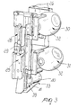
- a frame preferably made of plastics, in an upward region whereof holes 26 are defined for engaging the cover 20 by means of fixing screws which are not shown in the above figures for the sake of simplicity.
- the frame 25 has a structure which is mostly longitudinally elongated and on which two posts 27 are provided in which seats 28 are formed for accommodating magnetic switches 29.
- Each one of the switches 29 is of a per se known type and has, inside a bulb, a magnet and electrical contacts, not shown in the figures, which are directly connected, in this case, to an alarm circuit or to a disconnection circuit.
- An upper movable device 30 and an equivalent lower movable device 31 are fixed to the frame 25; each device is of a per se known type and comprises a floater 32 of the lever type.
- the upper movable device 30 directly actuates the alarm circuit in a per se known manner, while the lower movable device 31 is connected to the disconnection circuit.
- the relay 16 is provided with a movable device of the flap type, designated by the reference numeral 33, which is constituted by a flat member 37 from one end of which a pivot 35 protrudes.
- the two ends 36 of pivot 35 can rotatably engage the posts 27 of the frame 25, as specified in greater detail hereinafter.
- the flat member 37 has, in this configuration, a rectangular structure from which sides 39 perpendicular thereto protrude starting from the outer sides 38.
- the sides 39 are parallel and are kept together by a tubular support 40 which protrudes monolithically from them with an axis which is parallel to the pivot 35.
- tubular support 40 is suitable to contain a conveinently complementarily shaped cylindrical counterweight 41.
- the counterweight 41 is preferably made of brass.
- Sides 39 are flat, with a substantially trapezoidal plan which is delimited by the pivot 35 in an upward region and by the end 42 of the flat member 37 in a downward region.
- sides 39 uniformly distribute the effect of the presence of the counterweight 41 along the entire extension of the flat member 37.
- first prefractures 43 are formed in flat member 37 and are arranged longitudinally at the outer sides 38; second prefractures 44 are also provided therein and lie transversely so as to connect the first prefractures 43.
- the combination of the first and second prefractures 43 and 44 forms, on the flat member 37, detachable portions 45 starting from the lower end 42.
- the movable device of the flap type 33 is preferably made of plastics.
- Guides 46 are formed on the posts 27 of frame 25 in a region located below the lower movable device 32 of the floater type.
- the complementarily shaped ends 36 of the pivot 35 of the movable flap device 33 can be made to slide along guides 46.
- Each one of guides 46 has, in the innermost end portion of its extension, a seat 47 which is suitable to accommodate the end 36 of the pivot 35 of the movable flap device 33.
- the operation of the Buchholz relay 16 according to the present invention is extremely simple, since when the level of the oil lowers, the floater 32 of the upper device 30 directly actuates the alarm circuit.
- the relay 16 in particular, is sensitive to the occurrence of oil currents whose flow-rate exceeds a preset limit which can be determined by the end user.
- the movable flap device 33 When an oil current occurs whose flow-rate exceeds the limit set by the adjustment, the movable flap device 33 in fact rotates with respect to the frame 25 so as to directly actuate said disconnection circuit.
- the flow-rate limit is determined by the extent of the surface of the flat member 37, so that in order to achieve maximum sensitivity of intervention of the flap device 33 it is sufficient to use a flat member 37 which comprises all its detachable portions 45.
- the user wishes to adjust the intervention of the flap device 33 so as to increase the allowed flow-rate, for example going from a minimum allowed flow-rate limit (i.e., a maximum-sensitivity limit) obtained with the flat member 37 complete with all the portions 45, to a higher flow-rate limit, it is sufficient to detach a suitable number of portions 45 by way of said first and second prefractures 43 and 44.
- a minimum allowed flow-rate limit i.e., a maximum-sensitivity limit
- the manufacturer can produce Buchholz relays without having to differentiate any of their components and leaving the end user the freedom to choose the intervention threshold in case of oil currents.
- a fundamental advantage achieved with the present invention is that a Buchholz relay has been provided which, without having to differentiate the production process, allows end users to choose the degree of sensitivity of intervention of the relay in the presence of oil currents.
- Buchholz relay of the invention allows to set the intervention threshold in case of oil currents in a manner which is extremely simple and fast to perform and most of all is absolutely precise.
Landscapes
- Physics & Mathematics (AREA)
- Fluid Mechanics (AREA)
- Engineering & Computer Science (AREA)
- Power Engineering (AREA)
- Breakers (AREA)
- Organic Insulating Materials (AREA)
- Superconductors And Manufacturing Methods Therefor (AREA)
- Transition And Organic Metals Composition Catalysts For Addition Polymerization (AREA)
Claims (4)
- Relais de Buchholz (16), comprenant, afin d'être immergé dans un bain d'huile, un cadre de support (25) pour des interrupteurs magnétiques (29) destinés à fermer des circuits mis en fonctionnement par des dispositifs mobiles (30, 31), dont au moins un est du type flotteur (32) et au moins un est du type à clapet (33) associé de manière rotative avec ledit cadre (25), dans lequel ledit dispositif à clapet mobile (33) est indépendant desdits flotteurs (32) et comprend un élément plat (37) prévu avec un pivot (35) associé de manière rotative avec ledit cadre (25) au moyen de ses extrémités (36), ledit dispositif à clapet mobile (33) ayant également une surface sensible à la présence de courants d'huile de sorte que ledit dispositif à clapet mobile (33) puisse effectuer une rotation par rapport audit cadre (25) sous l'action d'un courant d'huile, au moins une portion de ladite surface du dispositif à clapet mobile (33) sensible à la présence de courants d'huile étant également réductible, caractérisé en ce que des fractures préalables (43, 44) sont formées dans ledit élément plat (37) de façon à constituer ladite surface réductible, lesdites fractures préalables (43, 44) formant au moins une portion détachable (45).
- Relais (16) selon la revendication 1, caractérisé en ce que ledit dispositif à clapet mobile (33) comporte un support tubulaire (40) à l'intérieur duquel un contre poids (41) peut être inséré.
- Relais (16) selon la revendication 1, caractérisé en ce que des guides mutuellement opposés (46) pour le coulissement des extrémités (36) dudit pivot (35) sont formés dans ledit cadre (25), chaque guide (46) se terminant par un siège (47) qui est adapté pour l'insertion par pression desdites extrémités (36).
- Relais (16) selon la revendication 1, caractérisé en ce que ledit dispositif à clapet mobile (33) est fabriqué à partir de plastique.
Applications Claiming Priority (2)
| Application Number | Priority Date | Filing Date | Title |
|---|---|---|---|
| IT98PD000059A ITPD980059A1 (it) | 1998-03-19 | 1998-03-19 | Rele' perfezionato di tipo buchholz |
| ITPD980059 | 1998-03-19 |
Publications (3)
| Publication Number | Publication Date |
|---|---|
| EP0944150A2 EP0944150A2 (fr) | 1999-09-22 |
| EP0944150A3 EP0944150A3 (fr) | 2000-06-07 |
| EP0944150B1 true EP0944150B1 (fr) | 2008-06-25 |
Family
ID=11392109
Family Applications (1)
| Application Number | Title | Priority Date | Filing Date |
|---|---|---|---|
| EP99104014A Expired - Lifetime EP0944150B1 (fr) | 1998-03-19 | 1999-03-12 | Relais de Buchholz amélioré |
Country Status (5)
| Country | Link |
|---|---|
| EP (1) | EP0944150B1 (fr) |
| AT (1) | ATE399384T1 (fr) |
| DE (1) | DE69938946D1 (fr) |
| ES (1) | ES2310020T3 (fr) |
| IT (1) | ITPD980059A1 (fr) |
Families Citing this family (7)
| Publication number | Priority date | Publication date | Assignee | Title |
|---|---|---|---|---|
| AU2002100385A4 (en) * | 2002-05-15 | 2002-06-20 | John Owen Williams | Improvement to the design and construction of a Buchholz type relay for transformer protection |
| ITVI20070223A1 (it) * | 2007-08-07 | 2009-02-08 | Comem Spa | Rele di buchholz per la protezione di apparecchiature elettriche di potenza isolate in olio. |
| CN103718258A (zh) * | 2011-07-25 | 2014-04-09 | Abb技术有限公司 | 用于电力变压器的安全设备和监测方法以及相关的电力变压器 |
| EP2669910B1 (fr) * | 2012-05-31 | 2015-07-01 | ABB Technology AG | Dispositif de sécurité pour transformateurs électriques et transformateur électrique associé |
| CN104134576A (zh) * | 2014-07-16 | 2014-11-05 | 国家电网公司 | 三引脚干簧管型双路跳闸节点瓦斯继电器 |
| EP3098827B1 (fr) * | 2015-05-26 | 2018-10-17 | ABB Schweiz AG | Système réglable d'évent d'écoulement pour relais de buchholz |
| CN113327819A (zh) * | 2021-06-25 | 2021-08-31 | 沈阳明远电气科技有限公司 | 气体继电器容积预报警装置及方法 |
Family Cites Families (4)
| Publication number | Priority date | Publication date | Assignee | Title |
|---|---|---|---|---|
| US2952753A (en) * | 1958-06-27 | 1960-09-13 | Mcdonnell & Miller Inc | Flow switch |
| ES324856A1 (es) * | 1965-03-30 | 1967-02-16 | Licentia Patent-Verwaltungs G M B H | Sistema de vigilancia y de desconexion para aparatos electricos con aislamiento liquido. |
| US4282413A (en) * | 1979-07-02 | 1981-08-04 | Grunau Company, Inc. | Liquid flow indicator |
| DD207645A3 (de) | 1982-02-04 | 1984-03-07 | Dietrich Kroll | Stauklappe fuer schutzeinrichtungen |
-
1998
- 1998-03-19 IT IT98PD000059A patent/ITPD980059A1/it unknown
-
1999
- 1999-03-12 DE DE69938946T patent/DE69938946D1/de not_active Expired - Lifetime
- 1999-03-12 ES ES99104014T patent/ES2310020T3/es not_active Expired - Lifetime
- 1999-03-12 AT AT99104014T patent/ATE399384T1/de not_active IP Right Cessation
- 1999-03-12 EP EP99104014A patent/EP0944150B1/fr not_active Expired - Lifetime
Also Published As
| Publication number | Publication date |
|---|---|
| ITPD980059A1 (it) | 1999-09-19 |
| DE69938946D1 (de) | 2008-08-07 |
| EP0944150A3 (fr) | 2000-06-07 |
| EP0944150A2 (fr) | 1999-09-22 |
| ES2310020T3 (es) | 2008-12-16 |
| ATE399384T1 (de) | 2008-07-15 |
Similar Documents
| Publication | Publication Date | Title |
|---|---|---|
| EP0944150B1 (fr) | Relais de Buchholz amélioré | |
| US4728914A (en) | Rating plug enclosure for molded case circuit breakers | |
| US20100060392A1 (en) | Relay | |
| US4660009A (en) | Modular integral circuit interrupter | |
| US2192060A (en) | Locking device | |
| EP0945951B1 (fr) | Relais de Buchholz d'accumulation de gaz amélioré | |
| DE69908138D1 (de) | Schalterpol mit integriertem optischen stromsensor | |
| US3732517A (en) | Protective fuse | |
| US3761777A (en) | Electric circuit breaker with electronic trip control unit | |
| EP2176875B1 (fr) | Agencement d'ajustement d'ecoulement pour un relais de buchholz | |
| US10804057B2 (en) | Method for replacement of mercury switches in a switchgear with alternative switch types | |
| US2457879A (en) | Protecting device for transformers | |
| US2509935A (en) | Protective means for electrical instrumentalities | |
| EP2688081B1 (fr) | Dispositif de sécurité destiné à un transformateur de puissance et transformateur de puissance associé utilisant un tel dispositif de sécurité | |
| US3916258A (en) | Fuse holder assembly | |
| US1709724A (en) | Transformer-tap-changing system | |
| KR100331022B1 (ko) | 변압기 탭의 수동 절환장치 | |
| US4324961A (en) | Distribution transformer having a primary disconnect switch | |
| US6175289B1 (en) | Electronic trip device with a removable voltage switch module | |
| JPH08329800A (ja) | 断路器 | |
| US3873797A (en) | Switch position indicator for electromagnetic switchgear | |
| EP3098827B1 (fr) | Système réglable d'évent d'écoulement pour relais de buchholz | |
| US3860898A (en) | Circuit breaker for distribution transformer | |
| US4210887A (en) | Circuit interrupter with interlocked interchangeable trip unit | |
| US2027541A (en) | Electric circuit controlling device of the thermal overload type |
Legal Events
| Date | Code | Title | Description |
|---|---|---|---|
| PUAI | Public reference made under article 153(3) epc to a published international application that has entered the european phase |
Free format text: ORIGINAL CODE: 0009012 |
|
| AK | Designated contracting states |
Kind code of ref document: A2 Designated state(s): AT BE CH DE ES FI FR GB GR LI NL PT SE |
|
| AX | Request for extension of the european patent |
Free format text: AL;LT;LV;MK;RO;SI |
|
| PUAL | Search report despatched |
Free format text: ORIGINAL CODE: 0009013 |
|
| AK | Designated contracting states |
Kind code of ref document: A3 Designated state(s): AT BE CH CY DE DK ES FI FR GB GR IE IT LI LU MC NL PT SE |
|
| AX | Request for extension of the european patent |
Free format text: AL;LT;LV;MK;RO;SI |
|
| 17P | Request for examination filed |
Effective date: 20001130 |
|
| AKX | Designation fees paid |
Free format text: AT BE CH DE ES FI FR GB GR LI NL PT SE |
|
| 17Q | First examination report despatched |
Effective date: 20070808 |
|
| GRAP | Despatch of communication of intention to grant a patent |
Free format text: ORIGINAL CODE: EPIDOSNIGR1 |
|
| GRAS | Grant fee paid |
Free format text: ORIGINAL CODE: EPIDOSNIGR3 |
|
| GRAA | (expected) grant |
Free format text: ORIGINAL CODE: 0009210 |
|
| AK | Designated contracting states |
Kind code of ref document: B1 Designated state(s): AT BE CH DE ES FI FR GB GR LI NL PT SE |
|
| REG | Reference to a national code |
Ref country code: GB Ref legal event code: FG4D |
|
| REG | Reference to a national code |
Ref country code: CH Ref legal event code: EP |
|
| REF | Corresponds to: |
Ref document number: 69938946 Country of ref document: DE Date of ref document: 20080807 Kind code of ref document: P |
|
| REG | Reference to a national code |
Ref country code: SE Ref legal event code: TRGR |
|
| PG25 | Lapsed in a contracting state [announced via postgrant information from national office to epo] |
Ref country code: NL Free format text: LAPSE BECAUSE OF FAILURE TO SUBMIT A TRANSLATION OF THE DESCRIPTION OR TO PAY THE FEE WITHIN THE PRESCRIBED TIME-LIMIT Effective date: 20080625 Ref country code: AT Free format text: LAPSE BECAUSE OF FAILURE TO SUBMIT A TRANSLATION OF THE DESCRIPTION OR TO PAY THE FEE WITHIN THE PRESCRIBED TIME-LIMIT Effective date: 20080625 |
|
| REG | Reference to a national code |
Ref country code: ES Ref legal event code: FG2A Ref document number: 2310020 Country of ref document: ES Kind code of ref document: T3 |
|
| NLV1 | Nl: lapsed or annulled due to failure to fulfill the requirements of art. 29p and 29m of the patents act | ||
| PG25 | Lapsed in a contracting state [announced via postgrant information from national office to epo] |
Ref country code: PT Free format text: LAPSE BECAUSE OF FAILURE TO SUBMIT A TRANSLATION OF THE DESCRIPTION OR TO PAY THE FEE WITHIN THE PRESCRIBED TIME-LIMIT Effective date: 20081125 |
|
| PG25 | Lapsed in a contracting state [announced via postgrant information from national office to epo] |
Ref country code: BE Free format text: LAPSE BECAUSE OF FAILURE TO SUBMIT A TRANSLATION OF THE DESCRIPTION OR TO PAY THE FEE WITHIN THE PRESCRIBED TIME-LIMIT Effective date: 20080625 |
|
| PLBE | No opposition filed within time limit |
Free format text: ORIGINAL CODE: 0009261 |
|
| STAA | Information on the status of an ep patent application or granted ep patent |
Free format text: STATUS: NO OPPOSITION FILED WITHIN TIME LIMIT |
|
| 26N | No opposition filed |
Effective date: 20090326 |
|
| REG | Reference to a national code |
Ref country code: CH Ref legal event code: PL |
|
| GBPC | Gb: european patent ceased through non-payment of renewal fee |
Effective date: 20090312 |
|
| PG25 | Lapsed in a contracting state [announced via postgrant information from national office to epo] |
Ref country code: LI Free format text: LAPSE BECAUSE OF NON-PAYMENT OF DUE FEES Effective date: 20090331 Ref country code: CH Free format text: LAPSE BECAUSE OF NON-PAYMENT OF DUE FEES Effective date: 20090331 |
|
| PG25 | Lapsed in a contracting state [announced via postgrant information from national office to epo] |
Ref country code: GB Free format text: LAPSE BECAUSE OF NON-PAYMENT OF DUE FEES Effective date: 20090312 |
|
| PG25 | Lapsed in a contracting state [announced via postgrant information from national office to epo] |
Ref country code: GR Free format text: LAPSE BECAUSE OF FAILURE TO SUBMIT A TRANSLATION OF THE DESCRIPTION OR TO PAY THE FEE WITHIN THE PRESCRIBED TIME-LIMIT Effective date: 20080926 |
|
| PGFP | Annual fee paid to national office [announced via postgrant information from national office to epo] |
Ref country code: SE Payment date: 20110314 Year of fee payment: 13 Ref country code: FR Payment date: 20110404 Year of fee payment: 13 Ref country code: FI Payment date: 20110314 Year of fee payment: 13 |
|
| PGFP | Annual fee paid to national office [announced via postgrant information from national office to epo] |
Ref country code: DE Payment date: 20110325 Year of fee payment: 13 Ref country code: ES Payment date: 20110322 Year of fee payment: 13 |
|
| REG | Reference to a national code |
Ref country code: SE Ref legal event code: EUG |
|
| PG25 | Lapsed in a contracting state [announced via postgrant information from national office to epo] |
Ref country code: FI Free format text: LAPSE BECAUSE OF NON-PAYMENT OF DUE FEES Effective date: 20120312 Ref country code: SE Free format text: LAPSE BECAUSE OF NON-PAYMENT OF DUE FEES Effective date: 20120313 |
|
| REG | Reference to a national code |
Ref country code: FR Ref legal event code: ST Effective date: 20121130 |
|
| PG25 | Lapsed in a contracting state [announced via postgrant information from national office to epo] |
Ref country code: FR Free format text: LAPSE BECAUSE OF NON-PAYMENT OF DUE FEES Effective date: 20120402 |
|
| REG | Reference to a national code |
Ref country code: DE Ref legal event code: R119 Ref document number: 69938946 Country of ref document: DE Effective date: 20121002 |
|
| REG | Reference to a national code |
Ref country code: ES Ref legal event code: FD2A Effective date: 20130710 |
|
| PG25 | Lapsed in a contracting state [announced via postgrant information from national office to epo] |
Ref country code: ES Free format text: LAPSE BECAUSE OF NON-PAYMENT OF DUE FEES Effective date: 20120313 |
|
| PG25 | Lapsed in a contracting state [announced via postgrant information from national office to epo] |
Ref country code: DE Free format text: LAPSE BECAUSE OF NON-PAYMENT OF DUE FEES Effective date: 20121002 |