EP0944220B1 - Dispositif de montage d'un diaphragme acoustique dans des radiotéléphones - Google Patents
Dispositif de montage d'un diaphragme acoustique dans des radiotéléphones Download PDFInfo
- Publication number
- EP0944220B1 EP0944220B1 EP19990301940 EP99301940A EP0944220B1 EP 0944220 B1 EP0944220 B1 EP 0944220B1 EP 19990301940 EP19990301940 EP 19990301940 EP 99301940 A EP99301940 A EP 99301940A EP 0944220 B1 EP0944220 B1 EP 0944220B1
- Authority
- EP
- European Patent Office
- Prior art keywords
- housing
- diaphragm
- holders
- housing according
- audio
- Prior art date
- Legal status (The legal status is an assumption and is not a legal conclusion. Google has not performed a legal analysis and makes no representation as to the accuracy of the status listed.)
- Expired - Lifetime
Links
- 230000015572 biosynthetic process Effects 0.000 claims description 3
- 238000005755 formation reaction Methods 0.000 claims description 3
- 230000002093 peripheral effect Effects 0.000 claims description 3
- 230000008878 coupling Effects 0.000 claims description 2
- 238000010168 coupling process Methods 0.000 claims description 2
- 238000005859 coupling reaction Methods 0.000 claims description 2
- 238000003466 welding Methods 0.000 claims description 2
- 230000004044 response Effects 0.000 description 6
- 230000000694 effects Effects 0.000 description 3
- 238000000034 method Methods 0.000 description 3
- 230000005236 sound signal Effects 0.000 description 3
- 230000008901 benefit Effects 0.000 description 2
- 230000001413 cellular effect Effects 0.000 description 2
- 238000004891 communication Methods 0.000 description 2
- 230000001154 acute effect Effects 0.000 description 1
- 239000000853 adhesive Substances 0.000 description 1
- 230000001070 adhesive effect Effects 0.000 description 1
- 230000008859 change Effects 0.000 description 1
- 238000010276 construction Methods 0.000 description 1
- 230000001186 cumulative effect Effects 0.000 description 1
- 230000001066 destructive effect Effects 0.000 description 1
- 230000006866 deterioration Effects 0.000 description 1
- 230000003467 diminishing effect Effects 0.000 description 1
- 229920001971 elastomer Polymers 0.000 description 1
- 239000000806 elastomer Substances 0.000 description 1
- 230000006872 improvement Effects 0.000 description 1
- 230000009467 reduction Effects 0.000 description 1
- 230000000717 retained effect Effects 0.000 description 1
Images

Classifications
-
- H—ELECTRICITY
- H04—ELECTRIC COMMUNICATION TECHNIQUE
- H04M—TELEPHONIC COMMUNICATION
- H04M1/00—Substation equipment, e.g. for use by subscribers
- H04M1/02—Constructional features of telephone sets
- H04M1/03—Constructional features of telephone transmitters or receivers, e.g. telephone hand-sets
- H04M1/035—Improving the acoustic characteristics by means of constructional features of the housing, e.g. ribs, walls, resonating chambers or cavities
-
- H—ELECTRICITY
- H04—ELECTRIC COMMUNICATION TECHNIQUE
- H04M—TELEPHONIC COMMUNICATION
- H04M1/00—Substation equipment, e.g. for use by subscribers
- H04M1/02—Constructional features of telephone sets
- H04M1/0202—Portable telephone sets, e.g. cordless phones, mobile phones or bar type handsets
- H04M1/026—Details of the structure or mounting of specific components
Definitions
- the present invention generally relates to an audio diaphragm for a radio telephone handset, and more particularly is concerned with how such an audio diaphragm can be mounted in a radio telephone handset.
- the handset has a microphone, an ear piece/speaker transducer and a ringer.
- a microphone the diaphragm is modulated by sound
- a speaker transducer the diaphragm is sound modulating.
- the handset may be provided with additional audio transducers for facilitating other audio functions such as handsfree telephony.
- audio diaphragms are mounted in one of a number different ways. Common methods of mounting the diaphragm include attaching it directly to the front or back cover of the handset or supporting it on an internal assembly plate carrying other components of the handset. To give one example, in one known type of handset, a speaker diaphragm is attached to an internal chassis which is bounded by a printed circuit board.
- a handset speaker diaphragm for example for hands-free usage.
- a speaker diaphragm in response to an electrical signal, produces sound waves which propagate simultaneously in forward and rearward directions substantially in opposite phases. Owing for example to internal reflections of the sound waves occurring in the handset, sound waves having opposing phases are caused to meet one another leading to some destructive interference taking place between the forward sound waves and the rearward sound waves, thus resulting in sound cancellation.
- the overall effect is a reduction in the output sound pressure level, as well as frequency response change. Given the restricted surroundings of a radio telephone handset, and the comparatively low operating frequency of handset speaker diaphragms, the problems of sound cancellation are particularly marked.
- the present invention seeks to address some of the shortcomings of known arrangements for mounting an audio diaphragm/transducer in a radio telephone handset.
- the present invention provides a housing and device as provided in the claims.
- the rear air loading can be calculated and carefully controlled so as to prevent acoustical standing waves from forming.
- the introduction of this design invariance ensures that the frequency response of the audio diaphragm can be readily predicted.
- the housing is provided with two apertures on oppositely facing walls of the housing for retaining two audio diaphragms.
- This arrangement has the added advantage of providing a compact holder for two audio diaphragms; the mutual acoustic interference between the two diaphragms being substantially reduced.
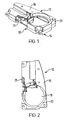
- housing (10) of the present invention.
- the housing (10) is made up of an upper diaphragm holder (12) and a lower diaphragm holder (14).
- the upper diaphragm holder (12) is constructed from a retaining plate (16) having formed therein an aperture (18) which is designed to receive an audio diaphragm (not shown).
- the retaining plate (16) is provided with an integrally formed continuous side wall (20) which extends around its perimeter.
- the retaining plate (16) has a recess running around the circumference of the aperture (18) and forming a shoulder (22).
- the audio diaphragm is located in the aperture (18) with a peripheral rim of the diaphragm locating against the shoulder (22).
- the audio diaphragm is fixed in place against the shoulder (22) e.g. by the use of adhesive.
- Some kind of gasket means could be used between the diaphragm and the shoulder (22) and of course between the diaphragm and the housing of the handset.
- the correct position and orientation of the diaphragm can be assured with one or several locating formations included in the retaining plate (16) defining the circumference of the aperture. In this way, the positional relationship between the diaphragm and the housing can be fixed. This has the advantage that connectors between the diaphragm and the housing are accurately positioned. Such connectors are described below.
- the construction of the lower diaphragm holder (14) is broadly similar to that of the upper diaphragm holder (12) and will not therefore be described in detail. Suffice to say that the lower holder (14) is dimensionally substantially equivalent to the upper holder (12), save that the aperture is in a different position.
- the upper and lower diaphragm holders (12,14) are brought together in a back-to-back configuration so that respective retaining plates oppose one another with their apertures facing outwardly.
- the chamber is sealed when the audio diaphragms are mounted in the apertures in respective retaining plates.
- the result is an air tight housing for carrying two audio diaphragms.
- the acoustic interference between one diaphragm and another is thereby substantially reduced.
- the design of the chamber can be determined depending on the diaphragm and its requirements of output level.
- the chamber is not designed for accommodating two diaphragms which are provided in the handset but simply the one.
- the audio quality of one transducer is more critical than that of another diaphragm.
- the acoustic effect between the two diaphragms can still be reduced.
- the two should not be mounted in one housing having a single chamber.
- each of the holders can be a unitary housing so that when they are joined together there are two separated acoustic chambers/cavities.
- the two holders forming the housing provide separate acoustical rear spaces for both the diaphragms.
- This could also be achieved by a single wall separating the upper and lower holders.
- the separating wall could be included as a backplate on one of the holders (within the scope of the present invention), or as a backplate closing off one of the apertures (outside the scope of the present invention).
- the housing may be provided with electrical connectors in the form of spring contacts (24) for electrically coupling an audio diaphragm to a printed circuit board.
- Other connecting means can also be used.
- an elastomer connector (25) is provided as an alternative way to couple the housing to the printed circuit board.
- One advantageous way to reduce the size of the radio telephone handset could be to use a cover of the device as one of the retaining plates of the housing.
- the upper holder's outward facing surface is formed by the upper cover of the handset, and the lower holder's outward facing surface is formed by the lower cover of the handset.
- the diaphragms could be placed in the housing before ultrasonically welding together the two holders.
- the electrical connections (24, 25) could then be located for example on the side wall (20) for ease of assembly.
- Mobile telephones operating in a cellular radio network have become common and widely used personal communication devices.
- mobile phones are being equipped with a greater variety of functions diversifying both the telecommunication in itself and the use of mobile phones in connection with the telecommunication or as addition for required peripheral functions.
- One example of this new kind of a personal communication device is the Applicant's N9000 Communicator (Trade Mark) type of device, which is a relatively small, portable device having both Personal Digital Assistant (PDA) functions as well as the Cellular Mobile Telephone (CMT) functions.
- PDA Personal Digital Assistant
- CMT Cellular Mobile Telephone
- the invention described in this application is particularly advantageous in this kind of device having e.g. different user interfaces and multiple functions and possibly several audio diaphragms for different purposes.
- one audio diaphragm such a hands-free speaker could be retained in one holder of the housing and a further audio diaphragm such an earpiece could be mounted in another co-joining holder of the housing, or in a completely separate housing outside the scope of the present invention, or if it has diminishing acoustic properties as compared to the hands-free speaker it could be mounted elsewhere in the handset outside the scope of the present invention.
- Radio telephone handsets in this specification thus covers also these kinds of portable terminal devices.
Landscapes
- Engineering & Computer Science (AREA)
- Signal Processing (AREA)
- Physics & Mathematics (AREA)
- Acoustics & Sound (AREA)
- Telephone Set Structure (AREA)
Claims (14)
- Boîtier pour un dispositif terminal portable ayant un premier et un deuxième diaphragme acoustique, le boîtier étant assemblé à partir de supports de diaphragme acoustique supérieur et inférieur (12, 14), dans lequel
chaque support de diaphragme (12, 14) est construit à partir d'une plaque de retenue (16) dans laquelle est formée une ouverture (18) conçue pour recevoir un diaphragme acoustique et pourvue d'une paroi latérale continue (20) formée d'un seul tenant qui s'étend autour de son périmètre et d'un évidement s'étendant sur la circonférence de l'ouverture (18) et formant un épaulement (22) de telle sorte que, pendant l'assemblage, le diaphragme acoustique soit situé dans l'ouverture avec un bord périphérique du diaphragme acoustique respectif situé contre l'épaulement, et
les supports de diaphragme supérieur et inférieur (12, 14) sont réunis de telle sorte que les supports de diaphragme respectifs soient en regard l'un de l'autre avec leurs ouvertures (18) tournées vers l'extérieur. - Boîtier selon la revendication 1, le boîtier assemblé étant agencé pour produire une cavité acoustique arrière commune pour les diaphragmes.
- Boîtier selon la revendication 1, le boîtier assemblé étant agencé pour produire des cavités acoustiques arrière séparées pour chaque diaphragme.
- Boîtier selon la revendication 3, le boîtier assemblé comprenant une paroi de séparation pour définir des cavités acoustiques arrière respectives pour chaque diaphragme.
- Boîtier selon la revendication 4, dans lequel l'un des supports comprend une plaque arrière pour agir en tant que paroi de séparation.
- Boîtier selon l'une quelconque des revendications précédentes, dans lequel les supports de diaphragme supérieur et inférieur (12, 14) sont réunis dans une configuration dos à dos.
- Boîtier selon la revendication 6, le boîtier étant assemblé par soudage ultrasonique des supports (12, 14) l'un à l'autre dans la configuration dos à dos.
- Boîtier selon l'une quelconque des revendications précédentes, le boîtier étant pourvu de formations pour relier un ou plusieurs des diaphragmes à d'autres composants du dispositif terminal portable.
- Boîtier selon l'une quelconque des revendications précédentes, le boîtier étant pourvu de contacts à ressort (24) pour le couplage électrique d'un ou de plusieurs des diaphragmes à une carte de circuit imprimé du dispositif terminal portable.
- Boîtier selon l'une quelconque des revendications précédentes, dans lequel l'un des diaphragmes est destiné à un haut-parleur et l'autre diaphragme est destiné à une oreillette.
- Boîtier selon l'une quelconque des revendications précédentes, dans lequel l'un des supports (12, 14) est un couvercle du dispositif terminal portable.
- Boîtier selon l'une quelconque des revendications précédentes, dans lequel les supports (12, 14) sont des couvercles respectifs du dispositif terminal portable.
- Boîtier selon l'une quelconque des revendications précédentes, le boîtier étant destiné à un dispositif terminal portable comprenant une fonctionnalité de télécommunications.
- Dispositif terminal portable comprenant un boîtier selon l'une quelconque des revendications précédentes.
Priority Applications (1)
| Application Number | Priority Date | Filing Date | Title |
|---|---|---|---|
| EP10075447.2A EP2375704B1 (fr) | 1998-03-18 | 1999-03-15 | Agencements d'assemblage de diaphragme audio dans des combinés téléphoniques radio |
Applications Claiming Priority (2)
| Application Number | Priority Date | Filing Date | Title |
|---|---|---|---|
| GB9805794A GB2336499B (en) | 1998-03-18 | 1998-03-18 | Audio diaphragm mounting arrangements in radio telephone handsets |
| GB9805794 | 1998-03-18 |
Related Child Applications (2)
| Application Number | Title | Priority Date | Filing Date |
|---|---|---|---|
| EP10075447.2A Division-Into EP2375704B1 (fr) | 1998-03-18 | 1999-03-15 | Agencements d'assemblage de diaphragme audio dans des combinés téléphoniques radio |
| EP10075447.2A Division EP2375704B1 (fr) | 1998-03-18 | 1999-03-15 | Agencements d'assemblage de diaphragme audio dans des combinés téléphoniques radio |
Publications (3)
| Publication Number | Publication Date |
|---|---|
| EP0944220A2 EP0944220A2 (fr) | 1999-09-22 |
| EP0944220A3 EP0944220A3 (fr) | 2003-04-09 |
| EP0944220B1 true EP0944220B1 (fr) | 2015-04-22 |
Family
ID=10828812
Family Applications (2)
| Application Number | Title | Priority Date | Filing Date |
|---|---|---|---|
| EP19990301940 Expired - Lifetime EP0944220B1 (fr) | 1998-03-18 | 1999-03-15 | Dispositif de montage d'un diaphragme acoustique dans des radiotéléphones |
| EP10075447.2A Expired - Lifetime EP2375704B1 (fr) | 1998-03-18 | 1999-03-15 | Agencements d'assemblage de diaphragme audio dans des combinés téléphoniques radio |
Family Applications After (1)
| Application Number | Title | Priority Date | Filing Date |
|---|---|---|---|
| EP10075447.2A Expired - Lifetime EP2375704B1 (fr) | 1998-03-18 | 1999-03-15 | Agencements d'assemblage de diaphragme audio dans des combinés téléphoniques radio |
Country Status (3)
| Country | Link |
|---|---|
| US (1) | US6266516B1 (fr) |
| EP (2) | EP0944220B1 (fr) |
| GB (1) | GB2336499B (fr) |
Families Citing this family (4)
| Publication number | Priority date | Publication date | Assignee | Title |
|---|---|---|---|---|
| US6363139B1 (en) * | 2000-06-16 | 2002-03-26 | Motorola, Inc. | Omnidirectional ultrasonic communication system |
| US6484020B1 (en) * | 2000-09-01 | 2002-11-19 | Nokia Mobile Phones Ltd. | Portable communication device with a deployable ear bud |
| JP3946118B2 (ja) * | 2002-10-07 | 2007-07-18 | シチズン電子株式会社 | 発音体の構造 |
| JP3946117B2 (ja) * | 2002-10-07 | 2007-07-18 | シチズン電子株式会社 | 発音体の構造 |
Family Cites Families (17)
| Publication number | Priority date | Publication date | Assignee | Title |
|---|---|---|---|---|
| NL138004A (fr) * | 1942-12-30 | |||
| US4178488A (en) * | 1977-08-02 | 1979-12-11 | Toa Electric Co., Ltd. | Telephone set |
| US4163875A (en) * | 1978-02-09 | 1979-08-07 | Northern Telecom Limited | Telephone handset with transmitter having a one piece gasket for sealing and holding of transmitter members |
| AU577832B2 (en) * | 1984-06-29 | 1988-10-06 | Intel Corporation | Telephone handset assembly |
| US4984268A (en) * | 1988-11-21 | 1991-01-08 | At&T Bell Laboratories | Telephone handset construction |
| FI83576C (fi) | 1989-02-10 | 1991-07-25 | Nokia Mobira Oy | Foerfarande och kopplingsarrangemang foer reglering av ljudstyrkan vid en mobiltelefon. |
| US5210793A (en) * | 1990-11-07 | 1993-05-11 | Motorola, Inc. | Apparatus for mounting transducers |
| US5191602A (en) * | 1991-01-09 | 1993-03-02 | Plantronics, Inc. | Cellular telephone headset |
| CA2169641C (fr) * | 1993-08-18 | 2004-01-20 | Telefonaktiebolaget Lm Ericsson | Combine telephonique |
| FI98163C (fi) | 1994-02-08 | 1997-04-25 | Nokia Mobile Phones Ltd | Koodausjärjestelmä parametriseen puheenkoodaukseen |
| EP0685981B1 (fr) * | 1994-06-01 | 2001-08-29 | Harman Audio Electronic Systems GmbH | Haut-parleur |
| US5613222A (en) * | 1994-06-06 | 1997-03-18 | The Creative Solutions Company | Cellular telephone headset for hand-free communication |
| TW275174B (fr) * | 1994-09-20 | 1996-05-01 | Motorola Inc | |
| US5517574A (en) * | 1994-12-22 | 1996-05-14 | Motorola, Inc. | Dual function transducer housing |
| AU664970B3 (en) * | 1995-07-25 | 1995-12-07 | Gregory John Whyte | Acoustic communication device |
| DE69736059T2 (de) * | 1996-02-26 | 2006-11-09 | Nokia Corp. | Funktelefon |
| GB2316814B (en) | 1996-08-30 | 2001-02-28 | Nokia Mobile Phones Ltd | A radio telephone connector |
-
1998
- 1998-03-18 GB GB9805794A patent/GB2336499B/en not_active Expired - Lifetime
-
1999
- 1999-03-12 US US09/268,082 patent/US6266516B1/en not_active Expired - Lifetime
- 1999-03-15 EP EP19990301940 patent/EP0944220B1/fr not_active Expired - Lifetime
- 1999-03-15 EP EP10075447.2A patent/EP2375704B1/fr not_active Expired - Lifetime
Also Published As
| Publication number | Publication date |
|---|---|
| EP2375704A2 (fr) | 2011-10-12 |
| GB9805794D0 (en) | 1998-05-13 |
| US6266516B1 (en) | 2001-07-24 |
| GB2336499A (en) | 1999-10-20 |
| GB2336499B (en) | 2002-06-12 |
| EP0944220A3 (fr) | 2003-04-09 |
| EP2375704B1 (fr) | 2016-07-20 |
| EP2375704A3 (fr) | 2012-11-14 |
| EP0944220A2 (fr) | 1999-09-22 |
Similar Documents
| Publication | Publication Date | Title |
|---|---|---|
| US6064894A (en) | Portable radio telephone having improved speaker and housing assembly for handsfree and private operation | |
| CN100539612C (zh) | 扬声器组件和包括该扬声器组件的移动终端 | |
| KR100329134B1 (ko) | 스피커 조립체를 갖는 휴대용 전자 장치 | |
| US8005207B2 (en) | Microphone coupler system for a communication device | |
| EP1806026B1 (fr) | Ensembles formant haut-parleurs a double membrane avec des passages acoustiques et terminaux mobiles les comprenant | |
| KR100540678B1 (ko) | 휴대용 통신 단말장치 및 그에 사용되는 전기 음향 변환기 | |
| EP1865690B1 (fr) | Terminal portable | |
| US5216711A (en) | Telephone handset including directional microphone module | |
| CN108574919B (zh) | 一种移动终端 | |
| US6374120B1 (en) | Acoustic guide for audio transducers | |
| US20260046552A1 (en) | Electronic device | |
| CN216356802U (zh) | 一种移动终端设备 | |
| JP4571632B2 (ja) | 折りたたみ可能な端末のためのスピーカ配置 | |
| EP2375704B1 (fr) | Agencements d'assemblage de diaphragme audio dans des combinés téléphoniques radio | |
| CN115633297A (zh) | 一种电子设备 | |
| US8503970B1 (en) | Portable communication device and system with interchangeable speaker modules | |
| CN223584220U (zh) | 电子设备 | |
| JP2000232505A (ja) | 受話用電気音響変換装置 | |
| JP2009111696A (ja) | 携帯端末及びマイク実装方法 | |
| CN218772416U (zh) | 一种超薄微型扬声器系统及应用该系统的电子设备 |
Legal Events
| Date | Code | Title | Description |
|---|---|---|---|
| PUAI | Public reference made under article 153(3) epc to a published international application that has entered the european phase |
Free format text: ORIGINAL CODE: 0009012 |
|
| AK | Designated contracting states |
Kind code of ref document: A2 Designated state(s): AT BE CH CY DE DK ES FI FR GB GR IE IT LI LU MC NL PT SE |
|
| AX | Request for extension of the european patent |
Free format text: AL;LT;LV;MK;RO;SI |
|
| RAP1 | Party data changed (applicant data changed or rights of an application transferred) |
Owner name: NOKIA CORPORATION |
|
| PUAL | Search report despatched |
Free format text: ORIGINAL CODE: 0009013 |
|
| AK | Designated contracting states |
Kind code of ref document: A3 Designated state(s): AT BE CH CY DE DK ES FI FR GB GR IE IT LI LU MC NL PT SE |
|
| AX | Request for extension of the european patent |
Extension state: AL LT LV MK RO SI |
|
| 17P | Request for examination filed |
Effective date: 20031009 |
|
| 17Q | First examination report despatched |
Effective date: 20031031 |
|
| AKX | Designation fees paid |
Designated state(s): DE FR NL SE |
|
| 17Q | First examination report despatched |
Effective date: 20031031 |
|
| RAP1 | Party data changed (applicant data changed or rights of an application transferred) |
Owner name: NOKIA CORPORATION |
|
| GRAP | Despatch of communication of intention to grant a patent |
Free format text: ORIGINAL CODE: EPIDOSNIGR1 |
|
| INTG | Intention to grant announced |
Effective date: 20141106 |
|
| GRAS | Grant fee paid |
Free format text: ORIGINAL CODE: EPIDOSNIGR3 |
|
| RAP1 | Party data changed (applicant data changed or rights of an application transferred) |
Owner name: NOKIA TECHNOLOGIES OY |
|
| GRAA | (expected) grant |
Free format text: ORIGINAL CODE: 0009210 |
|
| AK | Designated contracting states |
Kind code of ref document: B1 Designated state(s): DE FR NL SE |
|
| REG | Reference to a national code |
Ref country code: DE Ref legal event code: R096 Ref document number: 69945315 Country of ref document: DE Effective date: 20150603 |
|
| REG | Reference to a national code |
Ref country code: NL Ref legal event code: T3 |
|
| REG | Reference to a national code |
Ref country code: DE Ref legal event code: R097 Ref document number: 69945315 Country of ref document: DE |
|
| PLBE | No opposition filed within time limit |
Free format text: ORIGINAL CODE: 0009261 |
|
| STAA | Information on the status of an ep patent application or granted ep patent |
Free format text: STATUS: NO OPPOSITION FILED WITHIN TIME LIMIT |
|
| 26N | No opposition filed |
Effective date: 20160125 |
|
| REG | Reference to a national code |
Ref country code: FR Ref legal event code: ST Effective date: 20161130 |
|
| PG25 | Lapsed in a contracting state [announced via postgrant information from national office to epo] |
Ref country code: FR Free format text: LAPSE BECAUSE OF NON-PAYMENT OF DUE FEES Effective date: 20160331 |
|
| PG25 | Lapsed in a contracting state [announced via postgrant information from national office to epo] |
Ref country code: SE Free format text: LAPSE BECAUSE OF FAILURE TO SUBMIT A TRANSLATION OF THE DESCRIPTION OR TO PAY THE FEE WITHIN THE PRESCRIBED TIME-LIMIT Effective date: 20150422 |
|
| PGFP | Annual fee paid to national office [announced via postgrant information from national office to epo] |
Ref country code: DE Payment date: 20180227 Year of fee payment: 20 Ref country code: NL Payment date: 20180314 Year of fee payment: 20 |
|
| REG | Reference to a national code |
Ref country code: DE Ref legal event code: R071 Ref document number: 69945315 Country of ref document: DE |
|
| REG | Reference to a national code |
Ref country code: NL Ref legal event code: MK Effective date: 20190314 |