EP0944221A2 - Kommunikationseinrichtung und Verfahren zu deren Betriebssteuerung - Google Patents
Kommunikationseinrichtung und Verfahren zu deren Betriebssteuerung Download PDFInfo
- Publication number
- EP0944221A2 EP0944221A2 EP99103720A EP99103720A EP0944221A2 EP 0944221 A2 EP0944221 A2 EP 0944221A2 EP 99103720 A EP99103720 A EP 99103720A EP 99103720 A EP99103720 A EP 99103720A EP 0944221 A2 EP0944221 A2 EP 0944221A2
- Authority
- EP
- European Patent Office
- Prior art keywords
- operating unit
- time
- main operating
- communication device
- subunit
- Prior art date
- Legal status (The legal status is an assumption and is not a legal conclusion. Google has not performed a legal analysis and makes no representation as to the accuracy of the status listed.)
- Granted
Links
- 238000004891 communication Methods 0.000 title claims abstract description 57
- 238000000034 method Methods 0.000 title claims abstract description 35
- 230000015654 memory Effects 0.000 claims abstract description 26
- 230000006870 function Effects 0.000 claims description 7
- 238000005265 energy consumption Methods 0.000 description 12
- 230000008569 process Effects 0.000 description 10
- 238000012544 monitoring process Methods 0.000 description 7
- 230000001276 controlling effect Effects 0.000 description 3
- 238000010586 diagram Methods 0.000 description 3
- 230000005540 biological transmission Effects 0.000 description 2
- 238000011161 development Methods 0.000 description 2
- 230000001105 regulatory effect Effects 0.000 description 2
- 238000012546 transfer Methods 0.000 description 2
- 230000008859 change Effects 0.000 description 1
- 238000005259 measurement Methods 0.000 description 1
- 230000009467 reduction Effects 0.000 description 1
- 238000004904 shortening Methods 0.000 description 1
- 230000007704 transition Effects 0.000 description 1
Images


Classifications
-
- H—ELECTRICITY
- H04—ELECTRIC COMMUNICATION TECHNIQUE
- H04B—TRANSMISSION
- H04B1/00—Details of transmission systems, not covered by a single one of groups H04B3/00 - H04B13/00; Details of transmission systems not characterised by the medium used for transmission
- H04B1/06—Receivers
- H04B1/16—Circuits
- H04B1/1607—Supply circuits
- H04B1/1615—Switching on; Switching off, e.g. remotely
-
- H—ELECTRICITY
- H04—ELECTRIC COMMUNICATION TECHNIQUE
- H04W—WIRELESS COMMUNICATION NETWORKS
- H04W52/00—Power management, e.g. Transmission Power Control [TPC] or power classes
- H04W52/02—Power saving arrangements
- H04W52/0209—Power saving arrangements in terminal devices
- H04W52/0225—Power saving arrangements in terminal devices using monitoring of external events, e.g. the presence of a signal
-
- Y—GENERAL TAGGING OF NEW TECHNOLOGICAL DEVELOPMENTS; GENERAL TAGGING OF CROSS-SECTIONAL TECHNOLOGIES SPANNING OVER SEVERAL SECTIONS OF THE IPC; TECHNICAL SUBJECTS COVERED BY FORMER USPC CROSS-REFERENCE ART COLLECTIONS [XRACs] AND DIGESTS
- Y02—TECHNOLOGIES OR APPLICATIONS FOR MITIGATION OR ADAPTATION AGAINST CLIMATE CHANGE
- Y02D—CLIMATE CHANGE MITIGATION TECHNOLOGIES IN INFORMATION AND COMMUNICATION TECHNOLOGIES [ICT], I.E. INFORMATION AND COMMUNICATION TECHNOLOGIES AIMING AT THE REDUCTION OF THEIR OWN ENERGY USE
- Y02D30/00—Reducing energy consumption in communication networks
- Y02D30/70—Reducing energy consumption in communication networks in wireless communication networks
Definitions
- the invention relates to a method for controlling a communication device, which has a main operating unit and a subunit, and a communication device, in particular a sub-module a mobile telecommunications unit that operates during regular recurring time slots exchanges data with a main module.
- a communication device in particular a mobile device Telecommunication unit, whose power supply using a Battery or a rechargeable battery
- the communication device is usually used for this purpose during idle times, i.e. during times when no operational functions be required in a standby state or energy saving mode offset, in which only the circuit devices with current be supplied, which are required to be fully functional if necessary to restore the communication device.
- fast clock generators are therefore switched off during the individual function blocks continue with a regulated voltage be supplied to the in the individual memories of the function blocks to keep stored operating status data stored.
- the object of the invention is a method to provide control of a communication device that a extremely low energy consumption and therefore a very long service life of the voltage source. It's also the job the invention a communication device controllable by this method to accomplish.
- this object is achieved by a method for controlling a Communication device with a main operating unit and Subunit solved, in which operating state data after an operating period the main operating unit in a status memory of the subunit be saved and the power supply of the main operating unit is turned off to the communication facility in to put an energy-saving mode, and after switching on the Power supply for the main operating unit the stored operating status data to carry out the operation of the communication device from the status memory during the following operating period be transferred to the main operating unit.
- the operating state data required for the communication device are stored in a status memory provided for this purpose, which is assigned to a subunit, so that the power supply for the main operating unit can be switched off completely because only the subunit with the status memory is supplied with voltage needs to be. After switching on the power supply for the next operating period then simply becomes the stored operating status data transferred back to the main operating unit so that they will be fully functional again at the beginning of the next operating period owns.
- a useful development of the invention is characterized by this that the power supply to the main operating unit after expiration a predetermined waiting time by means of a switch-on signal from the subunit is turned on.
- Both the storage of the operating status data as well as monitoring the switch-on time So run in the subunit, specifically for a low Energy consumption can be designed without sacrificing operational reliability affect the communication device.
- the time indicator provided according to the invention which according to switching on the main operating unit is to be generated in a fixed time interval before the start of the following operating period.
- an external one Event such as a received burst, which can be fixed, can be the actual start time of the following operating period with the compare the expected starting time to by an extension or shortening the energy saving mode the actual distance between the time indicator and the beginning of the following operating period on the set the specified distance.
- the following begins Operating period in which, for example, a transmission operation is carried out is counted from the time indicator after a specified one Time. It is the time indicator provided according to the invention is therefore a time indicator of the absolute time, both for setting the start of operating periods as well as to set the duration the energy saving mode can be used.
- the time interval of the time indicator from the start of the following operating period from Main operating unit is measured in order at a communication device, whose main operating unit works periodically, the duration of the optimize the effective shutdown time of the main operating unit.
- a sub-module of a mobile telecommunication unit that only works during certain time slots, their time interval through the communication protocol used By default, it is allowed to the main operating unit between two successive operating periods, i.e. between two Time slots to keep energy saving for as long as possible.
- the subunit depends on the waiting time the time interval between the time indicator and the start time of the following operating period is specified by the main operating unit.
- the switch-on time can be determined particularly easily if that End of the waiting time in the subunit with the help of a clocked counter is determined, its current count value with a corresponding to the waiting time first comparison value, that is to say the waiting time value which is transmitted from the main operating unit to the subunit.
- the Counter is restarted after the waiting time that the current counter value is compared with a second comparison value, using the time indicator to the main operating unit to determine the starting time the following operating period.
- the time indicator generated in this way is used to determine the start time the following operating period is required in principle any fixed, but usually by the circuit structure fixed predetermined time interval from the switch-on time the power supply, the end of the waiting time corresponds.
- the switch-on time can be changed for the power supply of the main operating unit to the predetermined time, which is on the one hand so late that the tent between two operating periods optimal for the energy saving mode is used, but on the other hand so early that the main operating unit has enough time to keep their fast clock generator stable ensure and the operating status data from the status memory for the following operating period.
- the counter using one supplied by the main operating unit Software reset command is started. This can be done in one Circuit for performing the method according to the invention the number the signal lines between the main operating unit and the subunit reduce since a data line is used for the reset command can be.
- the method according to the invention can expediently be used when the main operating unit's operating periods are recurring Time slots are matched during which the main operating unit with a higher-level communication device data exchanges, e.g. if the main operating unit of a sub-module a mobile telecommunication unit with its main module communicated via an air interface.
- Another development of the invention is characterized in that the following operating period due to an external event, at least during a period spanning several operating periods Occurs at regular intervals, particularly by one of the main operating unit burst to be received, that is, by a signal bundle is started as it is used in time division multiple access becomes.
- the process according to the invention can also be particularly advantageous use in higher-level communication facilities that Start the operating period regardless of external events. It is then provided that operating periods are started as soon as their start time was determined with the help of the time indicator.
- a particularly preferred embodiment of the invention is characterized by this that the main operating unit generates a switch-on-hold signal, to their power supply after switching on during the Maintain operating period and after the end of the operating period switch off yourself.
- a communication device in particular a Submodule of a mobile telecommunication unit, which during regular recurring time slots exchanges data with a main module, assigns a main operational unit to execute assigned Functions and a subunit on a status memory for operating status data the main operating unit and a timing circuit having the power supply for the main operating unit controls.
- the timing circuit has a clocked one Has counter, the counter output with an input of a comparison circuit which is the counter value from the counter with a comparison value determined by the main operating unit a switch-on signal for the power supply of the main operating unit generate, with an output of the comparison circuit to a holding circuit is applied, which outputs the switch-on signal for a period of time.
- timing circuit is a second comparison circuit has the counter value with a second comparison value compares in order to supply an output signal to the main operating unit, the one time indicator for determining the starting time of the following Operating period of the main operating unit delivers
- the output signal of the second comparison circuit of the main operating unit is supplied as an indicator signal via a gate circuit, which by is controlled by an enable signal that indicates the type of switch-on.
- a gate circuit which by is controlled by an enable signal that indicates the type of switch-on.
- the other operating status information act the information on whether the main operating unit from one completely switched off state or from the energy-saving mode is switched on.
- the counter of the subunit from a clock generator is clocked, which is integrated in another electronic device to which the communication device is assigned.
- the Electronic device associated with the communication device is provided, the number of those activated during the energy-saving mode Consumers in the subunit further reduced.
- the subunit does not require a voltage regulator, so by omitting it this usually in the energy-saving mode of the largest consumer a significant reduction in energy consumption is achieved.
- the subunit can be separated from the main operating unit arrange separately in the further electronic device so that for the voltage supply of the subunit the voltage source of the other Communication device can be used.
- the Battery or the accumulator of the communication device further relieved.
- FIG. 1 shows a communication device, in particular a sub-module a mobile telecommunications unit, with a main operating unit 10 and a subunit 11, which are shared by a voltage source 12 are supplied.
- the main operating unit 10 points as Control unit 13 has a microcomputer unit MCU, which is a functional block 14 controls for the implementation of data communication.
- the function block 14 is connected to a transmission / reception circuit 15, to which an antenna 16 is connected.
- An energy-saving mode control circuit is used to control the switch-off and switch-on processes of the main operating unit 10 17 provided, briefly in the following as a mode control circuit 17 is referred to.
- the subunit 11 has a status memory 18 in which operating status data the main operating unit 10 are stored, if the Power supply is completely switched off.
- a bus 19 with one Clock signal line 19 'and a data line 19' ' connects the main operating unit 10 with the subunit 11 in order to provide operating status data and Control data between the main operating unit 10 and the subunit 11 to be able to exchange.
- the main operating unit 10 is a timing circuit in the subunit 11 20 provided that a switch-on signal ON-NB for switching on again the main operating unit 10 to an OR gate for the next operating period 21 delivers, whose output signal as a switch-on signal ON Controls switch 22 in the power supply of the main operating unit 10.
- the OR gate 21 is also an on-hold signal ON-H supplied from the main operation unit 10.
- the subunit 11 has a control circuit 23 which, as far as required the transfer of information and data from the main operating unit 10 and their forwarding to the time circuit 20 controls.
- the timing circuit 20 comprises a counter 24 which counts clock signals CLK applied to an input 25 and which supplies the respective current counter value A to a first and a second comparison circuit 27 and 28 via an output 26.
- the first comparison circuit 27 is fed from the mode control circuit 17 of the main operating unit 10 via the bus 19 and the control circuit 23 to a waiting time T w (see FIG. 3) between the reset of the counter 24 and the switch-on time t e corresponding switch-on time value B with which the respective current counter value A of the counter 24 is compared.
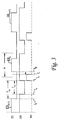
- the reset of the counter 24 can, as shown in FIG. 3, coincide with the end t E of the last operating period EB (n-1). With regard to the longest possible energy-saving mode, however, it is advantageous to restart the counter 24 at a predetermined point in time before the end of the current operating period.
- the first comparison circuit 27 If the current counter value A of the counter 24 is equal to the switch-on time value B, the first comparison circuit 27 outputs a corresponding signal to a holding circuit 29, which switches the switch-on signal ON-NB to the OR for a time (T e, max + ⁇ T e ) Gate 21 delivers. At the same time, the output signal of the first comparison circuit 27 is applied to the reset input R of the counter 24 in order to reset it.
- the counter 24 is also supplied with a reset signal TC, which may preferably be a software command, from the mode control circuit 17 via the bus 19 and the control circuit 23, in each case towards the end of an operating period Reset EBn of the main operating unit 10 for monitoring the switch-on time for the next operating period EB (n + 1).
- a reset signal TC which may preferably be a software command
- the second comparison circuit 28 receives an indicator time value via the control circuit 23 C and generates a logical signal IND ', for example gate circuit 30 designed as an AND gate as logic Signal IND is supplied to the main operating unit 10.
- the IND 'signal is logically "1" as long as the current counter value A is less than the indicator time value C is.
- the gate circuit 30 is released by an enable signal F as soon as the Communication device was switched on for the first time. Consequently after switching on the communication device for the first time the signal IND 'supplied by the second comparison circuit 28 as an indicator signal IND from the gate circuit 30 to the main operating unit 10 forwarded.
- the individual operating periods EB can, for example, by individual Receive bursts are defined, that is, by signal bundles such as those used for Time division multiple access methods are used.
- a reset signal TC via the data line 19 ′′ of the bus 19 and the control circuit 23 of the subunit 11 is output to the timing circuit 20 which resets the counter 24, which corresponds to starting the counter 24.
- the exit the first comparison circuit 27 and the output of the holding circuit 29 continue to supply the value logic "0", while the signal IND 'the second Comparison circuit 28 assumes the value logic "1". Since during the normal operation of the communication device, the release signal F has the value logic "1", the gate circuit 30 is released and gives the signal IND 'of the second comparison circuit 28 unchanged as an indicator signal IND to the main operating unit 10.
- the operating status data relevant for the next operating period the main operating unit 10 via the bus 19 to the subunit 11 transferred to be stored there in the status memory 18 become.
- a clock signal is sent via the clock signal line 19 'of the bus 19, the writing of the operating status data into the status memory 18 clocks.
- the fast clock signal of the main operating unit 10 generated by a fast clock generator can be used as the clock signal.
- the switch-on-hold signal EIN-H serving as a self-hold signal is set to the value logic "0", so that the output signal ON of the OR gate 21 also assumes the value "0" at time t a .
- the switch 22 that switches the voltage supply to the main operating unit 10 is set to its non-conductive state. The main operating unit 10 is thus completely switched off and the voltage source 12 only needs to supply the subunit 11.
- the indicator time value C and the release signal F delivers, as well as a relatively slow clock generator, not shown, the works in the kHz range, for example, supplied with voltage to become.
- the relatively slow one i.e. one with a low frequency Clock signal generator, which works for example at 32 kHz, enables a relatively low energy consumption since it is in the invention not on the absolute accuracy of the frequency of the clock signal generator arrives so that it can also be operated with an unregulated voltage can.
- the reduced energy consumption results in particular by dispensing with a voltage regulator, since voltage regulators are a consequence their quiescent currents usually have a relatively high power consumption cause.
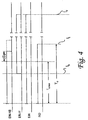
- the output signal of the first comparison circuit 27 assumes the value "1", so that the output signal ON-NB of the holding circuit 29 also assumes the value "1" which is held for a period of time to be described with reference to FIG. 4.
- the output signal ON-NB of the holding circuit 29 is applied via the OR gate 21 as an ON signal to the switch 22, so that the voltage supply for the main operating unit 10 is switched on.
- the counter 24 is reset.
- the signal IND 'of the second comparison circuit 28 thus assumes a value of logic "1", since the counter value A of the counter 24 after the reset is less than the indicator time value C.
- the signal IND ' is supplied to the main operating unit 10 via the gate circuit 30 as an indicator signal IND, since the release signal F in the described case, which is a restart from a waiting state or sleep mode, releases the gate circuit 30.
- the switch-on hold signal EIN-H assumes the value "1" at the time t b (see FIG. 4) after the end of the switch-on process for the main operating unit 10, the switch-on signal EIN-NB can again become “0" for the next operating period.
- the holding circuit 29 holds the switch-on signal ON-NB for the next operating period EBn at the value logic "1" until after the maximum time period T e , max for the switch-on process of the main operating unit 10, a time ⁇ T e has expired.
- the position of the switch-on time t e relative to the time t B of the actual one is determined by the mode control circuit 17
- the beginning of the following operating period which is characterized, for example, by the arrival of a burst in a telecommunications device, is monitored.
- the indicator signal IND is used, which changes from the value "1" to the value "0" at the time t i , when the counter value A of the counter 24 becomes equal to the indicator time value C.
- This transition serves as a time indicator which is assigned to the switch-on time t e via the indicator time value C.
- the indicator time value C thus corresponds to the time (t i -t e ) between switching on the main operating unit 10, that is to say resetting the counter 24 and reaching the indicator time value C.
- the time interval between the falling edge of the indicator signal IND at the time t i and the occurrence of the next burst, the beginning of which marks the start t B of the next operating period EBn, is determined, for example, by means of a counter of the mode control circuit 17 clocked by the fast clock generator of the main operating unit 10 detected with a predetermined target value (t B -t i) should compared.
- the setpoint is chosen positively, as shown in FIG. 3 in connection with the operating period EBn.
- the time indicator can be used not only for subordinate communication devices in which the operating periods are started by external events, but also for higher-level communication devices to determine the start of the following operating period.
- the elapsed after the occurrence of the time indicator is detected and time to the set value (t B -t i) for the time interval between the time indicator and the start time t B of the following operating period compared.
- the following operating period EB is started.
- the clock generator clocking the counter 24 is compared with the fast clock generator of the main operating unit 10.
- measurement and monitoring cycles are preferably carried out after the start-up of the communication device, in which the counter 24 of the subunit 11 is started towards the end of an operating period EB without, however, the voltage supply for the main operating unit 10 being switched off, as soon as after the switch-on instant t e at the time t i the time indicator, ie the falling edge of the indicator signal IND is detected, the count value of a fast counter of the main operating unit 10 is detected and stored as a nominal value. In normal operation, after the power supply for the main operating unit 10 is switched on, its fast counter is set to this nominal value as soon as the time indicator is determined.
- the count value present at time t i of the time indicator can be compared with the nominal value that should exist when the time indicator occurs, in order to change the waiting time value B for the first comparison circuit 27 of the time circuit 20 in accordance with this comparison so that the time indicator in each case is generated at the predetermined absolute time.
- a bus 19 with a data line 19 '' and a clock line 19 ' enables the connection between the main operating unit 10 and subunit 11 to be extremely simple in terms of circuitry, so that it is not only possible to subunit 11 within the communication device with regard to the voltage supply of to separate the main operating unit 10, but also to provide the subunit 11 separately from the main operating unit 10 in a communication device assigned to it, which operates in continuous operation.
- the time (t a -t E ) between the end of an operating period EB and the switching off of the power supply for the main operating unit 10 and the switch-on time T e are kept short so that the effective switch-off time T a of the main operating unit 10 becomes large between two successive operating periods EB.
Landscapes
- Engineering & Computer Science (AREA)
- Computer Networks & Wireless Communication (AREA)
- Signal Processing (AREA)
- Mobile Radio Communication Systems (AREA)
- Telephone Function (AREA)
- Selective Calling Equipment (AREA)
- Transceivers (AREA)
- Communication Control (AREA)
- Computer And Data Communications (AREA)
- Financial Or Insurance-Related Operations Such As Payment And Settlement (AREA)
Abstract
Description
Claims (21)
- Verfahren zum Steuern einer Kommunikationseinrichtung, die eine Hauptbetriebseinheit (10) und eine Untereinheit (11) aufweist,bei dem nach einer Betriebsperiode (EBn) Betriebszustandsdaten der Hauptbetriebseinheit (10) in einem Statusspeicher (18) der Untereinheit (11) gespeichert werden und danach die Spannungsversorgung der Hauptbetriebseinheit (10) abgeschaltet wird, um die Kommunikationseinrichtung in einen Energiesparmodus zu versetzen, undbei dem nach Einschalten der Spannungsversorgung für die Hauptbetriebseinheit (10) die gespeicherten Betriebszustandsdaten zur Durchführung des Betriebs der Kommunikationseinrichtung während der folgenden Betriebsperiode (EB(n+1)) aus dem Statusspeicher (18) zur Hauptbetriebseiheit (10) übertragen werden.
- Verfahren nach Anspruch 1, dadurch gekennzeichnet, daß die Spannungsversorgung der Hauptbetriebseinheit (10) nach Ablauf einer jeweils vorgegebenen Wartezeit (Tw) mittels eines Einschaltsignals (EIN) von der Untereinheit (11) eingeschaltet wird.
- Verfahren nach Anspruch 1 oder 2, dadurch gekennzeichnet, daß zu einem Zeitpunkt (ti) nach dem Einschalten der Spannungsversorgung der Hauptbetriebseinheit (10) ein Zeitindikator erzeugt wird, um den Anfangszeitpunkt (tB) der folgenden Betriebsperiode (EB) festzustellen.
- Verfahren nach Anspruch 3, dadurch gekennzeichnet, daß derzeitliche Abstand (tB-ti) des Zeitindikators vom Anfangszeitpunkt (tB) der folgenden Betriebsperiode (EB) von der Hauptbetriebseinheit (10) gemessen wird, um bei einer Kommunikationseinrichtung, deren Hauptbetriebseinheit (10) periodisch arbeitet, die Dauer (Ta) der effektiven Abschaltzeit der Hauptbetriebseinheit (10) zu optimieren.
- Verfahren nach Anspruch 3 oder 4, dadurch gekennzeichnet, daß der Untereinheit (11) die Wartezeit (Tw) in Abhängigkeit vom zeitlichen Abstand (tB-ti) des Zeitindikators vom Anfangszeitpunkt (tB) der folgenden Betriebsperiode (EB) von der Hauptbetriebseinheit (10) vorgegeben wird.
- Verfahren nach Anspruch 5, dadurch gekennzeichnet, daß die Wartezeit (Tw) für jede Betriebsperiode (EB) neu festgelegt werden kann.
- Verfahren nach Anspruch 2 bis 6, dadurch gekennzeichnet, daß das Ende der Wartezeit (Tw) in der Untereinheit (11) mit Hilfe eines getakteten Zählers (24) festgestellt wird, dessen laufender Zählwert (A) mit einem der Wartezeit (Tw) entsprechenden ersten Vergleichswert (B) verglichen wird, der von der Hauptbetriebseinheit (10) zur Untereinheit (11) übertragen wird.
- Verfahren nach Anspruch 7, dadurch gekennzeichnet, daß der Zähler (24) nach Ablauf der Wartezeit (Tw) neu gestartet wird, daß der laufende Zählerwert (A) mit einem zweiten Vergleichswert (C) verglichen wird, um den Zeitindikator an die Hauptbetriebseinheit (10) zu liefern, der zum Feststellen des Anfangszeitpunkts (tB) der folgenden Betriebsperiode (EB) dient.
- Verfahren nach Anspruch 7 oder 8, dadurch gekennzeichnet, daß der Zähler (24) mit Hilfe eines von der Hauptbetriebseinheit (10) gelieferten Software-Rücksetzbefehls (TC) gestartet wird.
- Verfahren nach einem der vorstehenden Ansprüche, dadurch gekennzeichnet, daß zum Speichern der Betriebszustandsdaten der Hauptbetriebseinheit (10) im Statusspeicher (18) der Untereinheit (11) und zum Lesen der Betriebszustandsdaten aus dem Statusspeicher (18) ein Taktsignal von der Hauptbetriebseinheit (10) zur Untereinheit (11) übertragen wird.
- Verfahren nach einem der vorstehenden Ansprüche, dadurch gekennzeichnet, daß die Betriebsperioden (EB) der Hauptbetriebseinheit (10) auf regelmäßig wiederkehrende Zeitschlitze abgestimmt sind, während denen die Hauptbetriebseinheit (10) mit einer übergeordneten Kommunikationseinrichtung Daten austauscht.
- Verfahren nach einem der vorstehenden Ansprüche, dadurch gekennzeichnet, daß Betriebsperioden (EB) durch ein äußeres Ereignis, das zumindest während eines mehrere Betriebsperioden (EB) umfassenden Zeitraums in regelmäßigen Abständen auftritt, insbesondere durch einen von der Hauptbetriebseinheit (10) zu empfangenden Burst gestartet werden.
- Verfahren nach einem der vorstehenden Ansprüche, dadurch gekennzeichnet, daß Betriebsperioden (EB) jeweils gestartet werden, sobald ihr Anfangszeitpunkt mit Hilfe des Zeitindikators festgestellt wurde.
- Verfahren nach einem der vorstehenden Ansprüche, dadurch gekennzeichnet, daß die Hauptbetriebseinheit (10) ein Einschalt-Haltesignal (EIN-H) erzeugt, um ihre Spannungsversorgung nach dem Einschalten während der Betriebsperiode (EB) aufrecht zu erhalten und nach Beendigung der Betriebsperiode (EB) selbst abzuschalten.
- Kommunikationseinrichtung; insbesondere Untermodul einer Telekommunikationseinheit, das während regelmäßig wiederkehrender Zeitschlitze mit einem Hauptmodul Daten austauscht; mit einer Hauptbetriebseinheit (10) zur Ausführung zugewiesener Funktionen und mit einer Untereinheit (11), die einen Statusspeicher (18) für Betriebszustandsdaten der Hauptbetriebseinheit (10) und einen Zeitschaltkreis (20) aufweist, der die Spannungsversorgung für die Hauptbetriebseinheit (10) steuert.
- Kommunikationseinrichtung nach Anspruch 15, dadurch gekennzeichnet, daß der Zeitschaltkreis (20) einen getakteten Zähler (24) aufweist, dessen Zählerausgang (26) mit einem Eingang einer Vergleichsschaltung (27) verbunden ist, die den Zählerwert (A) vom Zähler (24) mit einem von der Hauptbetriebseinheit (10) festgelegten Vergleichswert (B) vergleicht, um ein Einschaltsignal (EIN-NB) für die Spannungsversorgung der Hauptbetriebseinheit (10) zu erzeugen.
- Kommunikationseinrichtung nach Anspruch 16, dadurch gekennzeichnet, daß ein Ausgang der Vergleichsschaltung (27) an einen Haltekreis (29) angelegt ist, der das Einschaltsignal (EIN-NB) für eine Zeitdauer (Te,max+ΔTe) ausgibt.
- Kommunikationseinrichtung nach Anspruch 16 oder 17, dadurch gekennzeichnet, daß der Zeitschaltkreis (20) eine zweite Vergleichsschaltung (28) aufweist, die den Zählerwert (A) mit einem zweiten Vergleichswert (C) vergleicht, um der Hauptbetriebseinheit (10) ein Ausgangssignal (IND') zuzuführen, das einen Zeitindikator zum Feststellen des Anfangszeitpunkts (tB) der folgenden Betriebsperiode (EB) der Hauptbetriebseinheit (10) liefert.
- Kommunikationseinrichtung nach Anspruch 18, dadurch gekennzeichnet, daß das Ausgangssignal (IND') der zweiten Vergleichsschaltung (28) der Hauptbetriebseinheit (10) über eine Torschaltung (30) als Indikatorsignal (IND) zugeführt ist, die von einem Freigabesignal (F) gesteuert ist, das die Art des Einschaltvorgangs anzeigt.
- Kommunikationseinrichtung nach den Ansprüchen 15 bis 19, dadurch gekennzeichnet, daß der Zähler (24) der Untereinheit (11) von einem Taktgenerator getaktet ist, der in einer weiteren elektronischen Einrichtung integriert ist, der die Kommunikationseinrichtung zugeordnet ist.
- Kommunikationseinrichtung nach den Ansprüchen 15 bis 20, dadurch gekennzeichnet, daß zum Datenaustausch zwischen der Hauptbetriebseinheit (10) und der Untereinheit (11) ein Bus (19) mit einer Taktsignalleitung (19') und einer Datenleitung (10'') vorgesehen ist, so daß zum Speichern und Lesen der Betriebszustandsdaten im bzw. aus dem Statusspeicher (18) ein schneller Speicher- bzw. Lesetakt zur Untereinheit (11) übertragbar ist.
Applications Claiming Priority (2)
| Application Number | Priority Date | Filing Date | Title |
|---|---|---|---|
| DE19811853A DE19811853C1 (de) | 1998-03-18 | 1998-03-18 | Kommunikationseinrichtung und Verfahren zu deren Betriebssteuerung |
| DE19811853 | 1998-03-18 |
Publications (3)
| Publication Number | Publication Date |
|---|---|
| EP0944221A2 true EP0944221A2 (de) | 1999-09-22 |
| EP0944221A3 EP0944221A3 (de) | 2005-11-23 |
| EP0944221B1 EP0944221B1 (de) | 2010-10-27 |
Family
ID=7861386
Family Applications (1)
| Application Number | Title | Priority Date | Filing Date |
|---|---|---|---|
| EP99103720A Expired - Lifetime EP0944221B1 (de) | 1998-03-18 | 1999-02-25 | Kommunikationseinrichtung und Verfahren zu deren Betriebssteuerung |
Country Status (5)
| Country | Link |
|---|---|
| US (1) | US6487400B2 (de) |
| EP (1) | EP0944221B1 (de) |
| JP (1) | JP4307617B2 (de) |
| AT (1) | ATE486451T1 (de) |
| DE (2) | DE19811853C1 (de) |
Families Citing this family (9)
| Publication number | Priority date | Publication date | Assignee | Title |
|---|---|---|---|---|
| DE10024597B4 (de) * | 2000-05-21 | 2004-02-19 | Herterkom Gmbh | Telekommunikationsnetz |
| DE10157948A1 (de) * | 2001-11-27 | 2003-06-12 | Siemens Ag | Mobilfunk-Endgerät mit reduziertem Stromverbrauch |
| US20080288919A1 (en) * | 2007-05-14 | 2008-11-20 | Microsoft Corporation | Encoding of Symbol Table in an Executable |
| US8175099B2 (en) * | 2007-05-14 | 2012-05-08 | Microsoft Corporation | Embedded system development platform |
| JP5230006B2 (ja) * | 2008-12-24 | 2013-07-10 | 京セラ株式会社 | 情報処理システム、周辺装置、情報処理装置、省電力制御方法、およびプログラム |
| US8644203B2 (en) * | 2009-04-27 | 2014-02-04 | Dialog Semiconductor B.V. | Method of and device for reduced power consumption in synchronized systems |
| JP2011235493A (ja) * | 2010-05-07 | 2011-11-24 | Seiko Epson Corp | 通信装置 |
| JP5412383B2 (ja) * | 2010-07-21 | 2014-02-12 | シャープ株式会社 | 携帯通信端末 |
| US8478917B2 (en) | 2010-09-22 | 2013-07-02 | Microsoft Corporation | Automatic addressing protocol for a shared bus |
Citations (1)
| Publication number | Priority date | Publication date | Assignee | Title |
|---|---|---|---|---|
| EP0473465A1 (de) | 1990-08-27 | 1992-03-04 | Audiovox Corporation | Energiesparende Anordnung und Verfahren in einem tragbaren zellularem Fernsprechsystem |
Family Cites Families (22)
| Publication number | Priority date | Publication date | Assignee | Title |
|---|---|---|---|---|
| US4804954A (en) * | 1987-04-30 | 1989-02-14 | Motorola, Inc. | Battery saving method for portable communications receivers |
| JPH0642691B2 (ja) * | 1988-05-21 | 1994-06-01 | 富士通株式会社 | 移動電話端末 |
| US5150361A (en) * | 1989-01-23 | 1992-09-22 | Motorola, Inc. | Energy saving protocol for a TDM radio |
| GB2267797B (en) * | 1989-04-03 | 1994-04-13 | Mitsubishi Electric Corp | Mobile telephone device with low power consumption |
| FI89838C (fi) | 1990-08-30 | 1993-11-25 | Nokia Mobile Phones Ltd | Dynamiskt spaenningsintegreringsfoerfarande samt kopplingar foer utfoerande och tillaempande av foerfarandet |
| DE69225925T2 (de) * | 1991-04-17 | 1998-10-22 | Ericsson Telefon Ab L M | Zellulares Kommunikationssystem mit integrierten Funkrufsystem |
| FI88567C (fi) | 1991-07-04 | 1993-05-25 | Nokia Mobile Phones Ltd | En generell synkronisk 2N+1 -divisor |
| FI88837C (fi) | 1991-08-15 | 1993-07-12 | Nokia Mobile Phones Ltd | Frekvensdividering med udda tal och decimaltal |
| US5148473A (en) * | 1991-08-30 | 1992-09-15 | Motorola, Inc. | Pager and radiotelephone apparatus |
| US5289059A (en) | 1992-06-05 | 1994-02-22 | Nokia Mobile Phones, Ltd. | Switched capacitor decimator |
| FI95980C (fi) | 1992-09-04 | 1996-04-10 | Nokia Mobile Phones Ltd | Menetelmä ja kytkentäjärjestely ajan mittaamiseksi tarkasti epätarkalla kellolla |
| FI93684C (fi) | 1993-04-23 | 1995-05-10 | Nokia Mobile Phones Ltd | Menetelmä signaalin käsittelemiseksi ja menetelmän mukainen signaalinkäsittelypiiri |
| FI97597C (fi) * | 1993-12-23 | 1997-01-10 | Nokia Mobile Phones Ltd | Menetelmä matkaviestinjärjestelmän radiopuhelimen virrankulutuksen pienentämiseksi |
| US5581776A (en) | 1995-02-03 | 1996-12-03 | Nokia Mobile Phones Limited | Branch control system for rom-programmed processor |
| GB2298109B (en) | 1995-02-14 | 1999-09-01 | Nokia Mobile Phones Ltd | Data interface |
| FI953433A7 (fi) | 1995-07-14 | 1997-01-15 | Nokia Mobile Phones Ltd | Kaksiulotteista hilarakennetta käyttävä kanavatransistori ja sen käyttäminen signaalin prosessointiin |
| FI101256B (fi) | 1995-10-03 | 1998-05-15 | Nokia Mobile Phones Ltd | Menetelmä vastaanotetun signaalin ajoituksen mittaamiseksi tiedonsiirt ojärjestelmässä ja menetelmän toteuttava matkaviestin |
| DE19543858A1 (de) * | 1995-11-24 | 1997-05-28 | Deutsche Telekom Ag | Verfahren und Anordnung zur Reduzierung des Stromverbrauchs von schnurlosen Telefonen |
| FI962816A7 (fi) | 1996-07-11 | 1998-01-12 | Nokia Corp | Mikropiirimodulien kotelorakenne |
| US6253060B1 (en) * | 1996-12-20 | 2001-06-26 | Airnet Communications Corporation | Method and apparatus employing wireless remote loopback capability for a wireless system repeater to provide end-to-end testing without a wireline connection |
| US5995820A (en) * | 1997-06-17 | 1999-11-30 | Lsi Logic Corporation | Apparatus and method for calibration of sleep mode clock in wireless communications mobile station |
| GB2327792B (en) * | 1997-07-25 | 2001-09-12 | Nokia Mobile Phones Ltd | A data card housing |
-
1998
- 1998-03-18 DE DE19811853A patent/DE19811853C1/de not_active Expired - Lifetime
-
1999
- 1999-02-25 EP EP99103720A patent/EP0944221B1/de not_active Expired - Lifetime
- 1999-02-25 DE DE59915210T patent/DE59915210D1/de not_active Expired - Lifetime
- 1999-02-25 AT AT99103720T patent/ATE486451T1/de active
- 1999-03-12 US US09/267,030 patent/US6487400B2/en not_active Expired - Lifetime
- 1999-03-17 JP JP07186799A patent/JP4307617B2/ja not_active Expired - Lifetime
Patent Citations (1)
| Publication number | Priority date | Publication date | Assignee | Title |
|---|---|---|---|---|
| EP0473465A1 (de) | 1990-08-27 | 1992-03-04 | Audiovox Corporation | Energiesparende Anordnung und Verfahren in einem tragbaren zellularem Fernsprechsystem |
Also Published As
| Publication number | Publication date |
|---|---|
| EP0944221B1 (de) | 2010-10-27 |
| US6487400B2 (en) | 2002-11-26 |
| DE59915210D1 (de) | 2010-12-09 |
| DE19811853C1 (de) | 1999-09-09 |
| US20020123374A1 (en) | 2002-09-05 |
| ATE486451T1 (de) | 2010-11-15 |
| JPH11331060A (ja) | 1999-11-30 |
| JP4307617B2 (ja) | 2009-08-05 |
| EP0944221A3 (de) | 2005-11-23 |
Similar Documents
| Publication | Publication Date | Title |
|---|---|---|
| DE19530594C1 (de) | Verfahren und Vorrichtung zum Reduzieren des Energieverbrauchs bei einem durch einen Spannungswandler versorgten Elektrogerät | |
| EP0610700A1 (de) | Stromversorgungsschaltung für ein Gerät der Unterhaltungselektronik | |
| EP0981875A1 (de) | System zum übertragen von daten | |
| DE10231160A1 (de) | Unterbrechungsfreie Leistungsversorgung mit Lastabwurf | |
| DE19708979B4 (de) | System zur Datenkommunikation über einen optischen Bus und Verfahren zur Steuerung des Systems | |
| WO2001020433A1 (de) | Vorrichtung und verfahren zur stromversorgung von rechner-zusatzgeräten über das bussystem des rechners | |
| DE19811853C1 (de) | Kommunikationseinrichtung und Verfahren zu deren Betriebssteuerung | |
| EP0683593B1 (de) | Telekommunikationsanlage mit Energiesparmodus | |
| EP2159667B1 (de) | Computersystem und Verfahren zum Energie sparenden Betrieb eines Computersystems | |
| DE102007031528B4 (de) | Verfahren zur Schaltung eines Reglers mit geringem Spannungsabfall für einen Mikrocontroller | |
| EP0863639B1 (de) | System zum Übertragen von Daten | |
| WO2017017092A1 (de) | Elektrischer verbraucher für ein kraftfahrzeug | |
| DE102022120031B3 (de) | Elektronische steuereinheit, automobil-batteriemanagementsystem,system zum steuern eines elektromotors einesverkehrsmittels und verfahren zur implementierung einesisolierten hilfskanals zur ermöglichung einer digitalenversorgung auf der hochspannungsseite | |
| DE102006057223B4 (de) | Station-Steuerverfahren und dieses verwendende Station | |
| EP0803966A2 (de) | Netzteil für ein Gerät mit Standby-Betrieb | |
| DE60014764T2 (de) | Drucker und Ladegerät | |
| AT409206B (de) | Schaltungsanordnung zur stromversorgung einer netz-abschlusseinheit | |
| DE19815944C2 (de) | Energiesparschaltung für ein elektronisches Gerät und Steuerverfahren zur Energieeinsparung in einem elektronischen Gerät | |
| EP3602732A1 (de) | Verfahren zum betrieb einer elektrischen anlage mit einer mehrzahl an elektrischen verbrauchern, stromversorgungseinheit und elektrisch betriebene anlage | |
| DE3722799A1 (de) | Selektivrufempfaenger mit versorgungsspannungsverteiler | |
| EP0496024B1 (de) | Verfahren zur Reduzierung der Verlustleistung bei Einrichtungen zur berührungslosen Daten-und Energieübertragung sowie Anordnung zur Durchführung des Verfahrens | |
| EP0275566B1 (de) | Verfahren zur Reduzierung der Energieaufnahme einer Fernsprecheinrichtung, deren Versorgung mit elektrischer Energie über die Fernsprechleitung erfolgt, sowie Einrichtung zur Durchführung des Verfahrens | |
| DE102024210943B3 (de) | Betreiben einer Datenausleseeinrichtung für einen Tachographen | |
| DE2039710C3 (de) | ||
| DE3111584C2 (de) |
Legal Events
| Date | Code | Title | Description |
|---|---|---|---|
| PUAI | Public reference made under article 153(3) epc to a published international application that has entered the european phase |
Free format text: ORIGINAL CODE: 0009012 |
|
| AK | Designated contracting states |
Kind code of ref document: A2 Designated state(s): AT BE CH CY DE DK ES FI FR GB GR IE IT LI LU MC NL PT SE |
|
| AX | Request for extension of the european patent |
Free format text: AL;LT;LV;MK;RO;SI |
|
| RAP1 | Party data changed (applicant data changed or rights of an application transferred) |
Owner name: NOKIA CORPORATION |
|
| PUAL | Search report despatched |
Free format text: ORIGINAL CODE: 0009013 |
|
| AK | Designated contracting states |
Kind code of ref document: A3 Designated state(s): AT BE CH CY DE DK ES FI FR GB GR IE IT LI LU MC NL PT SE |
|
| AX | Request for extension of the european patent |
Extension state: AL LT LV MK RO SI |
|
| 17P | Request for examination filed |
Effective date: 20060209 |
|
| AKX | Designation fees paid |
Designated state(s): AT BE CH CY DE DK ES FI FR GB GR IE IT LI LU MC NL PT SE |
|
| GRAP | Despatch of communication of intention to grant a patent |
Free format text: ORIGINAL CODE: EPIDOSNIGR1 |
|
| GRAS | Grant fee paid |
Free format text: ORIGINAL CODE: EPIDOSNIGR3 |
|
| GRAA | (expected) grant |
Free format text: ORIGINAL CODE: 0009210 |
|
| AK | Designated contracting states |
Kind code of ref document: B1 Designated state(s): AT BE CH CY DE DK ES FI FR GB GR IE IT LI LU MC NL PT SE |
|
| REG | Reference to a national code |
Ref country code: GB Ref legal event code: FG4D Free format text: NOT ENGLISH |
|
| REG | Reference to a national code |
Ref country code: CH Ref legal event code: EP |
|
| REG | Reference to a national code |
Ref country code: IE Ref legal event code: FG4D Free format text: LANGUAGE OF EP DOCUMENT: GERMAN |
|
| REF | Corresponds to: |
Ref document number: 59915210 Country of ref document: DE Date of ref document: 20101209 Kind code of ref document: P |
|
| REG | Reference to a national code |
Ref country code: NL Ref legal event code: VDEP Effective date: 20101027 |
|
| REG | Reference to a national code |
Ref country code: IE Ref legal event code: FD4D |
|
| PG25 | Lapsed in a contracting state [announced via postgrant information from national office to epo] |
Ref country code: SE Free format text: LAPSE BECAUSE OF FAILURE TO SUBMIT A TRANSLATION OF THE DESCRIPTION OR TO PAY THE FEE WITHIN THE PRESCRIBED TIME-LIMIT Effective date: 20101027 Ref country code: FI Free format text: LAPSE BECAUSE OF FAILURE TO SUBMIT A TRANSLATION OF THE DESCRIPTION OR TO PAY THE FEE WITHIN THE PRESCRIBED TIME-LIMIT Effective date: 20101027 Ref country code: NL Free format text: LAPSE BECAUSE OF FAILURE TO SUBMIT A TRANSLATION OF THE DESCRIPTION OR TO PAY THE FEE WITHIN THE PRESCRIBED TIME-LIMIT Effective date: 20101027 Ref country code: PT Free format text: LAPSE BECAUSE OF FAILURE TO SUBMIT A TRANSLATION OF THE DESCRIPTION OR TO PAY THE FEE WITHIN THE PRESCRIBED TIME-LIMIT Effective date: 20110228 |
|
| PG25 | Lapsed in a contracting state [announced via postgrant information from national office to epo] |
Ref country code: GR Free format text: LAPSE BECAUSE OF FAILURE TO SUBMIT A TRANSLATION OF THE DESCRIPTION OR TO PAY THE FEE WITHIN THE PRESCRIBED TIME-LIMIT Effective date: 20110128 |
|
| PG25 | Lapsed in a contracting state [announced via postgrant information from national office to epo] |
Ref country code: ES Free format text: LAPSE BECAUSE OF FAILURE TO SUBMIT A TRANSLATION OF THE DESCRIPTION OR TO PAY THE FEE WITHIN THE PRESCRIBED TIME-LIMIT Effective date: 20110207 Ref country code: IE Free format text: LAPSE BECAUSE OF FAILURE TO SUBMIT A TRANSLATION OF THE DESCRIPTION OR TO PAY THE FEE WITHIN THE PRESCRIBED TIME-LIMIT Effective date: 20101027 |
|
| BERE | Be: lapsed |
Owner name: NOKIA CORPORATION Effective date: 20110228 |
|
| PG25 | Lapsed in a contracting state [announced via postgrant information from national office to epo] |
Ref country code: DK Free format text: LAPSE BECAUSE OF FAILURE TO SUBMIT A TRANSLATION OF THE DESCRIPTION OR TO PAY THE FEE WITHIN THE PRESCRIBED TIME-LIMIT Effective date: 20101027 |
|
| PLBE | No opposition filed within time limit |
Free format text: ORIGINAL CODE: 0009261 |
|
| STAA | Information on the status of an ep patent application or granted ep patent |
Free format text: STATUS: NO OPPOSITION FILED WITHIN TIME LIMIT |
|
| PG25 | Lapsed in a contracting state [announced via postgrant information from national office to epo] |
Ref country code: MC Free format text: LAPSE BECAUSE OF NON-PAYMENT OF DUE FEES Effective date: 20110228 |
|
| REG | Reference to a national code |
Ref country code: CH Ref legal event code: PL |
|
| 26N | No opposition filed |
Effective date: 20110728 |
|
| GBPC | Gb: european patent ceased through non-payment of renewal fee |
Effective date: 20110225 |
|
| PG25 | Lapsed in a contracting state [announced via postgrant information from national office to epo] |
Ref country code: CH Free format text: LAPSE BECAUSE OF NON-PAYMENT OF DUE FEES Effective date: 20110228 Ref country code: LI Free format text: LAPSE BECAUSE OF NON-PAYMENT OF DUE FEES Effective date: 20110228 |
|
| REG | Reference to a national code |
Ref country code: FR Ref legal event code: ST Effective date: 20111102 |
|
| REG | Reference to a national code |
Ref country code: DE Ref legal event code: R097 Ref document number: 59915210 Country of ref document: DE Effective date: 20110728 |
|
| PG25 | Lapsed in a contracting state [announced via postgrant information from national office to epo] |
Ref country code: BE Free format text: LAPSE BECAUSE OF NON-PAYMENT OF DUE FEES Effective date: 20110228 |
|
| PG25 | Lapsed in a contracting state [announced via postgrant information from national office to epo] |
Ref country code: IT Free format text: LAPSE BECAUSE OF FAILURE TO SUBMIT A TRANSLATION OF THE DESCRIPTION OR TO PAY THE FEE WITHIN THE PRESCRIBED TIME-LIMIT Effective date: 20101027 |
|
| PG25 | Lapsed in a contracting state [announced via postgrant information from national office to epo] |
Ref country code: FR Free format text: LAPSE BECAUSE OF NON-PAYMENT OF DUE FEES Effective date: 20110228 |
|
| PG25 | Lapsed in a contracting state [announced via postgrant information from national office to epo] |
Ref country code: GB Free format text: LAPSE BECAUSE OF NON-PAYMENT OF DUE FEES Effective date: 20110225 |
|
| REG | Reference to a national code |
Ref country code: AT Ref legal event code: MM01 Ref document number: 486451 Country of ref document: AT Kind code of ref document: T Effective date: 20110225 |
|
| PG25 | Lapsed in a contracting state [announced via postgrant information from national office to epo] |
Ref country code: AT Free format text: LAPSE BECAUSE OF NON-PAYMENT OF DUE FEES Effective date: 20110225 |
|
| PG25 | Lapsed in a contracting state [announced via postgrant information from national office to epo] |
Ref country code: LU Free format text: LAPSE BECAUSE OF NON-PAYMENT OF DUE FEES Effective date: 20110225 Ref country code: CY Free format text: LAPSE BECAUSE OF FAILURE TO SUBMIT A TRANSLATION OF THE DESCRIPTION OR TO PAY THE FEE WITHIN THE PRESCRIBED TIME-LIMIT Effective date: 20101027 |
|
| REG | Reference to a national code |
Ref country code: DE Ref legal event code: R081 Ref document number: 59915210 Country of ref document: DE Owner name: NOKIA TECHNOLOGIES OY, FI Free format text: FORMER OWNER: NOKIA CORP., 02610 ESPOO, FI |
|
| PGFP | Annual fee paid to national office [announced via postgrant information from national office to epo] |
Ref country code: DE Payment date: 20180214 Year of fee payment: 20 |
|
| REG | Reference to a national code |
Ref country code: DE Ref legal event code: R071 Ref document number: 59915210 Country of ref document: DE |