EP0944411B1 - Implantierbare, medizinische vorrichtung zur analyse von herzrythmusabweichungen - Google Patents
Implantierbare, medizinische vorrichtung zur analyse von herzrythmusabweichungen Download PDFInfo
- Publication number
- EP0944411B1 EP0944411B1 EP96944369A EP96944369A EP0944411B1 EP 0944411 B1 EP0944411 B1 EP 0944411B1 EP 96944369 A EP96944369 A EP 96944369A EP 96944369 A EP96944369 A EP 96944369A EP 0944411 B1 EP0944411 B1 EP 0944411B1
- Authority
- EP
- European Patent Office
- Prior art keywords
- heart rate
- rate variability
- heart
- beat
- abnormal
- Prior art date
- Legal status (The legal status is an assumption and is not a legal conclusion. Google has not performed a legal analysis and makes no representation as to the accuracy of the status listed.)
- Expired - Lifetime
Links
- 230000000747 cardiac effect Effects 0.000 claims description 62
- 230000002159 abnormal effect Effects 0.000 claims description 51
- 238000005259 measurement Methods 0.000 claims description 49
- 238000002560 therapeutic procedure Methods 0.000 claims description 36
- 230000015654 memory Effects 0.000 claims description 27
- 230000000694 effects Effects 0.000 claims description 20
- 230000000977 initiatory effect Effects 0.000 claims description 10
- 230000001965 increasing effect Effects 0.000 claims description 9
- 229940079593 drug Drugs 0.000 claims description 8
- 239000003814 drug Substances 0.000 claims description 8
- 238000012896 Statistical algorithm Methods 0.000 claims description 4
- 230000004962 physiological condition Effects 0.000 claims description 4
- 238000013480 data collection Methods 0.000 claims description 2
- 238000012545 processing Methods 0.000 claims description 2
- 230000003595 spectral effect Effects 0.000 claims description 2
- 230000002596 correlated effect Effects 0.000 claims 1
- 230000000875 corresponding effect Effects 0.000 claims 1
- 230000037361 pathway Effects 0.000 description 17
- 238000000034 method Methods 0.000 description 15
- 238000010586 diagram Methods 0.000 description 10
- 230000002861 ventricular Effects 0.000 description 10
- 238000004422 calculation algorithm Methods 0.000 description 9
- 230000001734 parasympathetic effect Effects 0.000 description 8
- 230000002889 sympathetic effect Effects 0.000 description 8
- UCTWMZQNUQWSLP-UHFFFAOYSA-N adrenaline Chemical compound CNCC(O)C1=CC=C(O)C(O)=C1 UCTWMZQNUQWSLP-UHFFFAOYSA-N 0.000 description 7
- 206010003119 arrhythmia Diseases 0.000 description 7
- 230000001746 atrial effect Effects 0.000 description 7
- 239000004020 conductor Substances 0.000 description 6
- 230000007423 decrease Effects 0.000 description 6
- 206010000891 acute myocardial infarction Diseases 0.000 description 5
- 239000008280 blood Substances 0.000 description 5
- 210000004369 blood Anatomy 0.000 description 5
- 208000006218 bradycardia Diseases 0.000 description 5
- 230000036471 bradycardia Effects 0.000 description 5
- 230000033001 locomotion Effects 0.000 description 5
- 208000001871 Tachycardia Diseases 0.000 description 4
- 230000001133 acceleration Effects 0.000 description 4
- 230000004913 activation Effects 0.000 description 4
- 230000006793 arrhythmia Effects 0.000 description 4
- 238000012544 monitoring process Methods 0.000 description 4
- 230000000638 stimulation Effects 0.000 description 4
- 230000006794 tachycardia Effects 0.000 description 4
- 238000009423 ventilation Methods 0.000 description 4
- 206010007559 Cardiac failure congestive Diseases 0.000 description 3
- 206010019280 Heart failures Diseases 0.000 description 3
- 206010049418 Sudden Cardiac Death Diseases 0.000 description 3
- QVGXLLKOCUKJST-UHFFFAOYSA-N atomic oxygen Chemical compound [O] QVGXLLKOCUKJST-UHFFFAOYSA-N 0.000 description 3
- 210000003403 autonomic nervous system Anatomy 0.000 description 3
- 230000036772 blood pressure Effects 0.000 description 3
- 206010061592 cardiac fibrillation Diseases 0.000 description 3
- 230000002060 circadian Effects 0.000 description 3
- 230000002600 fibrillogenic effect Effects 0.000 description 3
- 229910052760 oxygen Inorganic materials 0.000 description 3
- 239000001301 oxygen Substances 0.000 description 3
- 230000033764 rhythmic process Effects 0.000 description 3
- 206010047302 ventricular tachycardia Diseases 0.000 description 3
- UCTWMZQNUQWSLP-VIFPVBQESA-N (R)-adrenaline Chemical compound CNC[C@H](O)C1=CC=C(O)C(O)=C1 UCTWMZQNUQWSLP-VIFPVBQESA-N 0.000 description 2
- 206010047281 Ventricular arrhythmia Diseases 0.000 description 2
- 230000005856 abnormality Effects 0.000 description 2
- 230000008901 benefit Effects 0.000 description 2
- 230000002457 bidirectional effect Effects 0.000 description 2
- 238000004364 calculation method Methods 0.000 description 2
- 230000003247 decreasing effect Effects 0.000 description 2
- 230000002526 effect on cardiovascular system Effects 0.000 description 2
- 238000010304 firing Methods 0.000 description 2
- 230000006870 function Effects 0.000 description 2
- 210000002837 heart atrium Anatomy 0.000 description 2
- 208000019622 heart disease Diseases 0.000 description 2
- 208000010125 myocardial infarction Diseases 0.000 description 2
- 210000000653 nervous system Anatomy 0.000 description 2
- 238000006213 oxygenation reaction Methods 0.000 description 2
- 230000004213 regulation of atrial cardiomyocyte membrane depolarization Effects 0.000 description 2
- 230000034225 regulation of ventricular cardiomyocyte membrane depolarization Effects 0.000 description 2
- 238000011160 research Methods 0.000 description 2
- 230000029058 respiratory gaseous exchange Effects 0.000 description 2
- 230000035939 shock Effects 0.000 description 2
- 210000001013 sinoatrial node Anatomy 0.000 description 2
- 238000010183 spectrum analysis Methods 0.000 description 2
- 230000001515 vagal effect Effects 0.000 description 2
- 208000003663 ventricular fibrillation Diseases 0.000 description 2
- 210000000707 wrist Anatomy 0.000 description 2
- 208000001193 Accelerated Idioventricular Rhythm Diseases 0.000 description 1
- 206010003662 Atrial flutter Diseases 0.000 description 1
- 206010049993 Cardiac death Diseases 0.000 description 1
- 206010011906 Death Diseases 0.000 description 1
- 206010061216 Infarction Diseases 0.000 description 1
- 108091028043 Nucleic acid sequence Proteins 0.000 description 1
- 102100026827 Protein associated with UVRAG as autophagy enhancer Human genes 0.000 description 1
- 101710102978 Protein associated with UVRAG as autophagy enhancer Proteins 0.000 description 1
- 230000003213 activating effect Effects 0.000 description 1
- 229940102884 adrenalin Drugs 0.000 description 1
- 238000011366 aggressive therapy Methods 0.000 description 1
- 238000013459 approach Methods 0.000 description 1
- 230000002763 arrhythmic effect Effects 0.000 description 1
- 230000002567 autonomic effect Effects 0.000 description 1
- 239000003990 capacitor Substances 0.000 description 1
- 230000005189 cardiac health Effects 0.000 description 1
- 238000013194 cardioversion Methods 0.000 description 1
- 230000008859 change Effects 0.000 description 1
- 238000010276 construction Methods 0.000 description 1
- 208000029078 coronary artery disease Diseases 0.000 description 1
- 230000003292 diminished effect Effects 0.000 description 1
- 208000037265 diseases, disorders, signs and symptoms Diseases 0.000 description 1
- 208000035475 disorder Diseases 0.000 description 1
- 239000006185 dispersion Substances 0.000 description 1
- 230000009977 dual effect Effects 0.000 description 1
- 230000007831 electrophysiology Effects 0.000 description 1
- 238000002001 electrophysiology Methods 0.000 description 1
- 238000011156 evaluation Methods 0.000 description 1
- 230000000763 evoking effect Effects 0.000 description 1
- 230000001747 exhibiting effect Effects 0.000 description 1
- 230000035876 healing Effects 0.000 description 1
- 230000036541 health Effects 0.000 description 1
- 238000009532 heart rate measurement Methods 0.000 description 1
- 230000013632 homeostatic process Effects 0.000 description 1
- 238000001802 infusion Methods 0.000 description 1
- 230000002401 inhibitory effect Effects 0.000 description 1
- 230000003993 interaction Effects 0.000 description 1
- 230000001788 irregular Effects 0.000 description 1
- 231100000518 lethal Toxicity 0.000 description 1
- 230000001665 lethal effect Effects 0.000 description 1
- 206010025482 malaise Diseases 0.000 description 1
- 230000002503 metabolic effect Effects 0.000 description 1
- 230000004048 modification Effects 0.000 description 1
- 238000012986 modification Methods 0.000 description 1
- 238000012806 monitoring device Methods 0.000 description 1
- 210000003205 muscle Anatomy 0.000 description 1
- 230000008035 nerve activity Effects 0.000 description 1
- 230000001537 neural effect Effects 0.000 description 1
- 230000010355 oscillation Effects 0.000 description 1
- 230000035479 physiological effects, processes and functions Effects 0.000 description 1
- 230000002035 prolonged effect Effects 0.000 description 1
- 238000002407 reforming Methods 0.000 description 1
- 230000001105 regulatory effect Effects 0.000 description 1
- 230000000284 resting effect Effects 0.000 description 1
- 230000000717 retained effect Effects 0.000 description 1
- 230000001020 rhythmical effect Effects 0.000 description 1
- 210000005245 right atrium Anatomy 0.000 description 1
- 210000005241 right ventricle Anatomy 0.000 description 1
- 238000005070 sampling Methods 0.000 description 1
- 238000004904 shortening Methods 0.000 description 1
- 230000002269 spontaneous effect Effects 0.000 description 1
- 238000012360 testing method Methods 0.000 description 1
- 230000001225 therapeutic effect Effects 0.000 description 1
- 229940125725 tranquilizer Drugs 0.000 description 1
- 239000003204 tranquilizing agent Substances 0.000 description 1
- 230000002936 tranquilizing effect Effects 0.000 description 1
Images



Definitions
- the present invention relates to implantable medical devices for the stimulation of the heart and particularly to devices that respond to heart rate variability.
- human heartbeat was thought to be regulated according to classical principles of homeostasis. Under this theory, the human physiological system operates in a manner which adjusts heart rate variability to achieve a state of equilibrium. Clinicians, in fact, traditionally described the normal beat activity of the heart as a "regular or normal sinus rhythm.”
- Beat-to-beat fluctuations which occur around a person's mean heart rate are known as heart rate variability.
- the fluctuations from beat-to-beat are attributed, in part, to the nonlinear interaction between the sympathetic and parasympathetic branches of the involuntary nervous system.
- the sympathetic autonomic and parasympathetic autonomic nervous systems regulate, to some extent, the sinoatrial (SA) node and atrioventricular (AV) node of the heart and, thus, largely influence the control of the heart rate.
- SA sinoatrial
- AV atrioventricular
- These two nervous systems operate somewhat reciprocally to effect changes in the heart rate.
- parasympathetic stimulation decreases the firing rate of the pacing cells located in the sinus node of the heart.
- Sympathetic stimulation increases this firing rate.
- heart rate variability was increasingly recognized as a diagnostic and a prognostic indication of the cardiac health risks to which a person is susceptible.
- heart rate variability may provide important information to forecast impending cardiac anomalies.
- clinicians have been investigating the possibility that heart rate variability may provide important information to forecast impending cardiac anomalies.
- One study verified that a low standard deviation of heart rate variability is a powerful prognostic indicator of sudden coronary death in patients recovering from acute myocardial infarction. See Alberto Malliani, et. al, "Power Spectral Analysis of Cardiovascular Variability in Patients at Risk for Sudden Cardiac Death" Journal of Cardiovascular Electrophysiology, Vol. 5 (1994), pp. 274-286.
- Heart rate variability does have a correlation to the present condition of a person's heart rate or the future occurrence of an abnormal cardiac event.
- numerous studies have been performed which demonstrate this correlation. For example, if the heart rate of a healthy individual is compared to the rate of a patient having congestive heart failure, distinct differences in the beat intervals will be observed. In this regard, the healthy individual will exhibit more complex patterns of fluctuation than the non-healthy individual.
- Heart rate variability is an independent predictor of death when other known postinfarction risk variables (for example, prolonged left ventricular ejection fraction, ventricular arrhythmias, and clinical variables) are considered. Heart rate variability has a higher association with risk for death than other variables obtained by Holter monitoring, (for example, mean heart rate and ventricular arrhythmias). Heart rate variability also appears to be a better predictor of arrhythmia complications than prolongation of the ejection fraction. See Conny M. A. van Ravenswaaij-Arts, et . al, Annals of Internal Medicine, Vol. 118 (1993), pp. 436-447.
- Heart rate variability is one available predictive value. Recent studies in this field verify that a decrease or increase in heart rate variability during the first several weeks after an acute myocardial infarction may be used to predict subsequent mortality or ventricular rhythmic disorders.
- heart rate intervals generally have a circadian variation. This circadian variation, however, may begin to become less pronounced and more irregular several minutes to several hours before the onset of an abnormal cardiac event.
- researchers for example, have found that heart rate variability progressively decreases in the hours preceding the onset of arrhythmia. Monitoring heart rate variability in such instances thus provides clinicians with a tool to forecast impending cardiac events.
- measurements of heart rate variability are generally non-invasive and may be reliably performed.
- a Holter monitor or electrodes affixed to the patient measure heart rate very accurately.
- the electrodes detect the heartbeat, usually the R-R interval, for a series of beats.
- statistical data such as mean, median, and standard deviation, are computed and then used to forecast the onset of a cardiac event.
- One known method for using heart rate variability is to compare heart rate intervals recorded under normal heart rate conditions to subsequent heart rate intervals. Deviations between the two recordings then may be used as an indication of heart rate variability fluctuation.
- a Holter monitor records R-R intervals while the patient exhibits normal or healthy heart rate variability.
- An algorithm based on mean and standard deviation then computes a single user value which is stored in permanent memory.
- This user value represents the patient's stress state during normal heart rate variability conditions.
- the patient wears a wrist detector which monitors the R-R intervals for discrete beat periods, for example 100 beats. Once a beat period is complete, the wrist detector uses the algorithm to compute the patient's present user value or present stress state.
- This present user value is then compared to the permanently stored user value which was previously recorded under normal heart rate conditions. Theoretically, this comparison reveals deviations from normal heart rate variability which, in turn, are a measure of the patient's cardiac stress state. Large deviations between the two user values reflect large deviations in the autonomic nervous system balance between the sympathetic and parasympathetic activities. For example, if the presently recorded user value deviates from the permanently stored user value more than 25%, the patient may be subject to an elevated stress level with an accompanying abnormal heart rate variability.
- Heart rate variability algorithms typically first compute a present user value based on the R-R intervals. Thereafter, this present user value is compared with a previously stored user value and a deviation between the two is computed. The algorithmic structure itself, however, remains unchanged. Thus, when subsequent R-R intervals are received and new user values calculated, these values are again compared with the same permanently stored user value. As such, the algorithm repeatedly uses the same threshold parameters defining normal and abnormal heart rate variability.
- Heart rate variability data leading up to an abnormal cardiac event Another disadvantage associated with methods and apparatus for utilizing heart rate variability concerns the treatment of heart rate variability data leading up to an abnormal cardiac event.
- Devices measuring heart rate variability often have memories which operate on a first-in-first-out basis. These types of memories hold the heart rate data in sequence and discard the oldest data and save the newest, incoming data. The older data, however, may provide important information regarding the onset of subsequent cardiac events.
- the present invention is addressed to an apparatus for evaluating heart rate variability of a person in order to recognize or forecast a cardiac event.
- Heart rate variability zones initially are established to define normal and abnormal cardiac sinus rhythm of the person. Thereafter, these zones are automatically modified after the occurrence or non-occurrence of a cardiac event. As such, the bounds defining normal and abnormal heart rate variability specifically adapt to a person's physiological and cardiological conditions. Once a cardiac event occurs, a pathway leading up to that event is stored. Patient heart rate variability is then compared to this pathway to determine the re-occurrence of a cardiac event.
- a microprocessor-based cardiac stimulator receives heart-beat signals from the heart.
- the cardiac stimulator computes time intervals occurring between successive heart beats and then derives a measurement of heart rate variability from epoch data for predetermined time periods.
- This epoch data may include both statistical data derived from the time intervals and sensing data derived from patient sensors.
- the cardiac stimulator then compares measurement of heart rate variability with previously stored heart rate variability zones which define normal and abnormal heart rate variability. If the measurement of heart rate variability is within the limits of an abnormal heart rate variability zone then an appropriate therapy regime is initiated. On the other hand, if the measurement of heart rate variability is within a normal heart rate variability zone, a therapy regime is not initiated.
- the abnormal heart rate variability zone is modified to include the measurement of heart rate variability.
- the definition of normal and abnormal heart rate variability changes to meet the cardiac requirements of a particular individual.
- a memory permanently stores the present epoch data and, additionally, a series of epoch data leading up to the event. Together, this series of epoch data forms a pathway from a generally normal heart rate variability condition to an abnormal heart rate variability condition. This pathway aids in predicting the occurrence of future cardiac events and in identifying the occurrence of present cardiac events. In this regard, all measurements of heart rate variability occurring after the cardiac event are compared with the pathway. This comparison reveals whether the person is again experiencing conditions similar to those leading to the prior cardiac event.
- the abnormal heart rate variability zone may be divided into a plurality of abnormal subzones.
- Each of these subzones corresponds to a therapy regime for initiating further sensing or therapeutic vigilance.
- the therapy regimes may have a structure with progressively higher degrees of aggressiveness and vigilance.
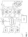
- FIG. 1 is a block diagram illustrating an implantable cardiac stimulator 10 for carrying out the teachings of the present invention.
- Stimulator 10 may be a pacemaker, defibrillator, or other implantable pulse generator.
- a microprocessor 12 provides control and computational facilities for stimulator 10.
- Microprocessor 12 has input/output ports connected in a conventional manner via bidirectional bus 14 to memory 16, an A-V interval timer 18, and a pacing interval timer 20.
- A-V interval timer 18 and pacing interval timer 20 have an output connected individually via lines 22 and 24, respectively, to a corresponding input port of microprocessor 12.
- A-V and pacing interval timers 18 and 20 may be external to microprocessor 12, as illustrated, or internal thereto. Additionally, these timers may be conventional up/down counters of the type that are initially loaded with a count value and count up to or down from the value and output a roll-over bit upon completing the programmed count. The initial count value is loaded into A-V and pacing interval timers 18 and 20 on bus 14. Respective roll-over bits are output to microprocessor 12 on lines 22 and 24.
- Memory 16 preferably includes both ROM and RAM. Generally, ROM stores operating routines, and RAM stores programmable parameters and variables.
- Microprocessor 12 preferably also has an input/output port connected to a telemetry interface 26 via line 28.
- Stimulator 10 when implanted, is thus able to receive variable and control parameters from an external programmer and to send data to an external receiver if desired. As such, operating parameters stored within microprocessor 12 may be selectively altered non-invasively.
- Many suitable telemetry systems are known to those skilled in the art.
- U.S. Pat. 4,539,992 by Calfee, et al ., issued September 10, 1985 and entitled "Method and Apparatus for Communicating with Implanted Body Function Stimulator" describes an example of a telemetry system and encoding arrangement.
- Control lines 30 and 32 connect microprocessor output ports to inputs of an atrial stimulus pulse generator 34 and a ventricular stimulus pulse generator 36, respectively.
- Pulse parameter data such as amplitude, width, enable/disable, and pulse initiation codes transmit to generators 34 and 36 via lines 30 and 32, respectively.
- control lines 38 and 40 connect microprocessor input ports to outputs of an atrial sense amplifier 42 and a ventricular sense amplifier 44, respectively.
- Atrial sense amplifier 42 detects the occurrences of P-waves
- ventricular sense amplifier 44 detects the occurrences of R-waves.
- the input of atrial sense amplifier 42 and the output of atrial stimulus pulse generator 34 connect to a first conductor 46 which connects to a first conventional type lead 48.
- An electrically conductive pacing/sensing tip 52 is located at a distal end of lead 48. This pacing/sensing tip electrically connects to conductor 46 and connects, for example, to heart 50 in right atrium 54.
- the input of ventricular sense amplifier 44 and the output of ventricular stimulus pulse generator 36 connects to a second conductor 56 which connects to a second conventional type lead 58.
- An electrically conductive pacing/sensing tip 62 is located at a distal end of lead 58. This pacing/sensing tip electrically connects to conductor 56 and connects, for example, to heart 50 in right ventricle 60. Leads 48 and 58 may be inserted into heart 50 transvenously or in any other suitable manner.
- Conductors 46 and 56 conduct the stimulus pulses generated in atrial and ventricular stimulus pulse generators 34 and 36, respectively, to pacing/sensing tips 52 and 62. Pacing/sensing tips 52 and 62 and corresponding conductors 46 and 56 also conduct sensed cardiac electrical signals in the heart to atrial and ventricular sense amplifiers 42 and 44.
- Cardiac stimulator 10 also may serve as a defibrillator.
- microprocessor 12 controls a high voltage defibrillator circuit 64.
- Two high voltage leads 66 and 68 connect to the heart with two electrodes 70 and 72.
- epicardial patch electrodes are diagrammatically represented; although, other electrode configurations, such as endocardial electrodes or others known to those skilled in the art, may be used.
- the input and output ports of microprocessor 12 also connect to various sensors 74 via a bidirectional control bus 76.
- Implantable cardiac stimulators often employ sensors or sensing capabilities.
- Sensors 74 may be a variety of different sensing devices which gather information about the patient. These sensors, for example, may sense ventilation, acceleration, activity, oxygen level, blood pressure, temperature, blood oxygenation, blood pH, impedance, adrenaline levels, or the like.
- the present invention may be used with various implantable devices, with stimulator 10 in FIG. 1 illustrating an example of one such device.
- Other possible implantable devices may be directed solely or jointly to tachycardias, bradycardias, or fibrillation, and, in this regard, comprise a defibrillator, a single or dual chamber pacer, or combinations thereof.
- the invention may be used in devices which do not stimulate the heart at all or devices which are not implantable. Such devices, however, must be able to sense or record the cardiac wave-form in order to measure the beat-to-beat intervals of the heart. Measurement of this interval may be done remotely from the heart, for example with electrodes placed on the patient, or within the heart itself, for example, from either the atrium, ventricle, or both.
- signals from the heart communicate from electrodes to the cardiac stimulator or other such monitoring device.
- sensing tip 52 or sensing tip 62 detects the heart's signals. Once these signals are detected, they may be processed in various ways to acquire the beat-to-beat intervals.
- U.S. Patent No. 5,201,321 by Fulton, issued April 13, 1993, and entitled “Method and Apparatus for Diagnosing Vulnerability to Lethal Cardiac Arrhythmias” teaches a method and apparatus for receiving heart beat signals and then calculating the beat-to-beat intervals.
- the signal received from the heart is digitized, and the output is provided to a peak detector which is connected to a memory.
- the peak detector measures the timing of the peak amplitude, such as the A-A, P-P, V-V, or R-R interval of the heart signal (A-A interval is the time between successive atrial depolarizations as measured from within the atrium; P-P interval is the time between successive atrial depolarizations as measured on the body of the patient; V-V interval is the time between successive ventricular depolarizations as measured from within the ventricle; and R-R interval is the time between successive ventricular depolarizations as measured on the body of the patient).
- the memory or recording device then stores the timing of the successive intervals.
- the timing intervals usually are measured in units of time or in terms of the number of samples between beats. The particular method or apparatus used to record the beat-to-beat intervals is less critical, as long as these intervals are accurately obtained.
- the beat-to-beat intervals are recorded during predetermined lengths of time or epochs.
- the epoch period typically will endure for several minutes, for example five minutes, or for a given number of heart beats, for example 100 to 1000 beats.
- the length of the epoch is programmable and may vary.
- beat-to-beat intervals are continuously recorded for successive epochs.
- the overall operating algorithm is illustrated in a discussion of the flow diagrams which follow.
- the flow diagrams represent the program structure under which microprocessor 12 preferably operates.
- the program structure may be written in a low level computer language, such as assembly, and retained in a memory within the microprocessor.
- a program structure commences at begin 100.
- conventional initialization procedures are performed. These procedures may include setting all pointers, registers, and counters, and clearing specified memory locations.
- Epoch statistical data then is selected, as depicted in block 104.
- This statistical data generally includes computational and statistical algorithms, variables, equations, and the like known to those of ordinary skill in the art. Typically, this statistical data will include any combination of at least one of a measure of central tendency or a measure of dispersion.
- Additional examples of statistical variables and equations which may be calculated for an epoch period include: mean, MAD (mean absolute deviation), median, mode (most commonly occurring heart rate variability interval), amplitude of mode (percentage that mode occurs), variation range (difference between highest and lowest heart rate variability interval), PNN50 (percentage of heart rate intervals having a duration longer than 50 ms), standard deviation, range, power spectral density, and variance.
- sensing data may be used in addition to statistical data.
- epoch sensor data is selected.
- Sensing data is derived from sensors or electrodes which measure physiological conditions of the patient. Such sensors may be directed toward sensing, for example: evoked QT intervals, respiration, stroke volume, central venous oxygen saturation, right ventricular pressure, blood pressure, muscle noise, acceleration, impedance, activity or motion, temperature, blood pH, and adrenaline.
- An activity sensor for example, is capable of measuring the movement and motion of the patient.
- Statistical equations/algorithms and sensing data may be utilized to evaluate heart rate variability.
- Statistical equations for example, may be used singly or incorporated into a statistical algorithm to produce statistical data for a given epoch. This statistical data, in turn, may be combined with sensing data. Together, the statistical and sensing data form the epoch data for a given epoch.
- Block 108 shows that heart rate variability zones and corresponding therapy regimes are designated and then stored into memory.
- the heart rate variability zones define normal and abnormal heart rate variability for the patient.
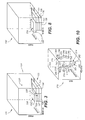
- FIG. 3 illustrates an exemplary heart rate variability zone configuration generally at 120. Three separate axes define configuration 120. Mean value of AA intervals defines the x-axis; PNN50 defines the y-axis; and patient activity defines the z-axis.
- an abnormal heart rate variability zone is shown generally at 122.
- a normal heart rate variability zone 124 occurs outside the boundaries of abnormal zone 122.
- a set of parameters defines the boundaries or limits of abnormal zone 122 and normal zone 124. These parameters include values or ranges of values for each of the three axes.
- the parameters divide abnormal zone 122 into a plurality of heart rate variability sub zones.
- FIG. 3 shows abnormal zone 122 subdivided into six different subzones 126-131, respectively. Separate and independent sets of parameters define each subzone 126-131.
- Each of the subzones corresponds to a different heart rate variability state, and the subzones may have a hierarchical format with respect to the level of abnormality of heart rate variability or with respect to the corresponding cardiac condition of the patient.
- subzone 126 may represent heart rate variability conditions with a more heightened degree of alert than subzone 129.
- each subzone In FIG. 3, a somewhat rectangular configuration illustrates each subzone. It will be appreciated that these configurations are for illustrative purposes and will vary depending on the parameters which define the bounds of the subzones. In addition, the configurations generally will depend not only on the statistical and sensor data selected to define the subzones but also on particular physiological conditions and requirements of an individual patient. In this regard, each patient undergoing heart rate variability analysis may require a different set of parameters defining each subzone 126-131. Further yet, the subzones may have a plurality of different parameters. In FIG. 3, three different parameters define abnormal zone 122. The number of parameters may vary from one to more than four or five. A fourth parameter, for example, could be time of day. Configuration 120 depicts three parameters and six subzones for illustration.
- the parameter's bounds or limits for each subzone may be established before heart rate variability analysis commences. For example, a doctor or clinician may assign specific numerical values for each of the subzones based on the medical history of a patient. Alternatively, the patient may undergo monitoring to determine limits for abnormal and normal heart rate variability. A Holter monitor or other device used to record and store heart rate variability data may monitor the heart rate variability of the patient. Thereafter, limits for each of the subzones may be calculated based on this data. As another alternative, the boundaries defining the subzones may be based on an initial estimation and pre-programmed into memory.
- Each subzone also has an associated therapy regime.
- the therapy regimes preferably have a hierarchical format with respect to the level of abnormality of heart rate variability or with respect to the corresponding cardiac condition of the patient. In this regard, a lesser degree of aggressiveness may be associated with a subzone having a more acceptable heart rate variability and a more aggressive therapy assigned to a subzone having more abnormal heart rate variability.
- FIG. 4 illustrates an exemplary therapy regime generally at 150.
- therapy regime 150 has eight different therapy levels 152-159.
- therapy level 152 calls for the initiation of more energy expensive tests or data acquiring procedures to better or more accurately assess the heart condition of the patient.
- These procedures may include various forms of added vigilance, such as activating a sensor which senses ventilation, acceleration, impedance, activity or motion, oxygen, blood pressure, temperature, blood oxygenation, blood pH, or adrenaline.
- the procedures may include increasing the level of diagnostic data collection, for example, waveform storage with increased sampling rate, increasing diagnostic biopotential channel bandwidth, increasing parameter recordings, and increasing signal processing.
- additional statistical data may be calculated or additional statistical algorithms employed.
- This statistical data may be based on heart rate intervals stored during current or previous epochs. Additionally, the initiation of completely non-invasive procedures are possible. For example, a warning or alarm may communicate to the patient, health provider, clinician, or a designated location. Such a warning, for example, could communicate the patient's pending heart condition or, alternatively, alert a clinician of the patient's condition or need for added attentiveness.
- therapy level 153 calls for bradycardia pacing or antibradycardia pacing. If the heart rate variability were more abnormal, a higher rate overdrive pacing would be implemented, as shown in therapy level 154.
- Level 155 illustrates antitachycardia pacing and would occur, for example, if the patient were experiencing atrial flutter or ventricular tachycardia.
- the next higher level 156 calls for a form of neural stimulation to stimulate vagal activity of the patient.
- Level 157 illustrates activation of a counteractive drug dose.
- a drug infusion pump could infuse drugs to the patient to counteract any increased adrenalin and act as a tranquilizer. As such, the drug would effectively normalize heart rate variability.
- a cardioversion shock may be initiated, as shown at level 158.
- An extreme level 159 calls for administering a defibrillation shock if the patient exhibits even more extreme cardiac conditions or exhibits extreme abnormal heart rate variability.
- a heightened degree of vigilance generally is not initiated until the patient exhibits an abnormal heart rate variability.
- a therapy regime such as shown in levels 152-159. Possible regimes, as noted, include additional sensing, computing, or the like. Since these regimes require power to initiate, selective activation saves energy.
- non-essential computational and diagnostic activity occurring within the stimulator may be suspended, halted, or not commenced in order to reduce potential sources of interference and devote computational resources to monitoring and diagnosing heart rate variability or a cardiac event. For example, if an abnormal heart rate variability is detected, unnecessary reforming of a defibrillator capacitor may be stopped.
- Each therapy level 152-159 may correspond to a different heart rate variability subzone.
- subzone 126 may correspond with therapy level 152
- subzone 131 corresponds with therapy level 159.
- FIG. 4 illustrates an example of one therapy regime. However, alternative therapy regimes may differ for individual patients and be tailored to meet specific cardiac requirements.
- time domain analysis or a frequency domain analysis are two common ways researchers use to examine heart rate variability.
- a graph typically displays the R-R intervals as the number of beats occurring during a specified time.
- ECG monitors may record and calculate heart rate variability.
- a Fourier transform algorithm decomposes sequential R-R intervals into a sum of sinusoidal functions.
- a graph typically displays the result of this algorithm and shows the amplitude of the patient's heart rate fluctuations at different oscillation frequencies.
- the frequency domain analysis is particularly advantageous in some instances because certain frequency bands within the spectral analysis are associated with autonomic nervous system control of sinus node period. See J. Thomas Bigger, et. al, "Frequency Domain Measures of Heart Period Variability and Mortality After Myocardial Infarction" Circulation, Vol. 85 (1992), pp. 164-171.
- the program structure begins at 170 and commences conventional initialization procedures at 172. Next, as shown in block 174, measurement of successive heart beat signals occurs. Then, as represented at 176, the beat-to-beat intervals between heart beats of the patient is calculated. These intervals represent the time period between successive beats. A memory stores the intervals, as shown in block 178. Next, a query is made at block 180 to determine whether the beat-to-beat interval has a length of time greater or less than 50 ms. If the beat-to-beat interval is greater than or equal to 50 ms, then a counter is incremented at 182.
- a counter is incremented at 184.
- the counters may be in the microprocessor or control circuitry and count the number of times during a single epoch the beat-to-beat intervals are greater or less than 50 ms.
- a query determines if the epoch period ended. If the epoch period has not ended, then the program structure returns to block 174 and continues to measure intervals between successive heart beats. If the epoch has ended, statistical data is calculated for the epoch, as shown at 188. The statistical data calculated at 188 is calculated for the data collected during the epoch. As illustrated in FIG. 3, the statistical data may also include, for example, PNN50 and Mean.
- the statistical data is stored into memory, as shown in block 190.
- counts one and two, the timing of the intervals, and the time of day also are stored.
- the program structure of FIG. 5 repeats, as shown along line 192, and again begins to measure heart beat intervals and calculate statistical data for succeeding epoch periods.
- a program structure commences selected sensing of the patient and calculation of sensing data.
- the program structure begins at 200 and initiates conventional initialization procedures at 202.
- selected sensors are initiated and begin to collect information for the current epoch period.
- FIG. 3 illustrates initiation of an acceleration, activity, or motion sensor.
- a query is made at block 206 to determine whether the epoch period has ended. If the epoch period has not ended, then the program structure returns to block 204 and continues to collect information.
- the program structure proceeds to block 208, and the sensors selected in block 204 calculate sensing data for the epoch. For example, activity signals received during the epoch may be averaged to indicate a mean activity rate As shown in block 210, memory stores the sensing data and the time of day. At the end of the epoch, the program structure of FIG. 6 repeats, as shown along line 212, and again begins to sense using the selected sensors.
- FIG. 7 a program structure is shown for modifying stored heart rate variability zones which were previously stored into memory.
- the heart rate variability zones are automatically customized to adapt to an individual person's physiological and cardiological conditions.
- the program structure begins at 216 and then proceeds to block 218 which specifies collecting epoch data and deriving a measurement of heart rate variability.
- Epoch data including sensing and statistical data, is collected and calculated as described in connection with FIGS. 2, 5, and 6.
- the measurement of heart rate variability is derived from the epoch data. This measurement of variability represents a measure of the person's or subject's heart rate variability for a given epoch period and includes all of the epoch data or selected portions.
- a query in block 220 is made as to whether the end of the epoch period is reached. If the answer is negative, then epoch data is continued to be collected. If the answer is affirmative, the program structure continues to block 222 and a query is made whether present measurement of heart rate variability is within an abnormal heart rate variability zone.
- FIG. 3 illustrates this occurrence. As shown, three different axes (mean AA, PNN50, and activity) define abnormal heart rate variability zone 122 and normal heart rate variability zone 124. The measurement of heart rate variability is compared with zones 122 and 124 to determine the present cardiac condition and heart rate variability of the patient for the present epoch.
- FIG. 3 shows a possible location 226 within subzone 128. If, on the other hand, the present measurement of heart rate variability is not within abnormal heart rate variability zone 122, then the query of block 228 is presented. FIG. 3 shows a possible location 230 within normal zone 124 and outside the bounds of abnormal zone 122.
- Block 228 queries whether the stimulator or measuring device is detecting any form of abnormal cardiac condition.
- the stimulator may be initiating a therapy, detecting a cardiac event, or within a heightened alarm, warning, or sensing condition.
- the patient may be experiencing a degree of tachycardia, bradycardia, fibrillation, dysrhythmia, arrhythmia, or the like.
- the program structure proceeds to block 232 and the epoch data, including the measurement of heart rate variability, is temporarily saved into memory.
- heart rate variability zone configuration 120 of FIG. 3 is modified to include the measurement of heart rate variability corresponding to the present epoch sensor and statistical data. Modification, for example, may include enlarging or shortening the boundaries of one or more of subzones 129-131. Memory then stores the epoch data and measurement of heart rate variability as shown in block 236.
- FIG. 3 illustrates a possible location 238 which is not initially within abnormal zone 122. Thus, no therapy would be initiated due to heart rate variability data of the patient. However, if the stimulator or measuring device concurrently detects an abnormal cardiac condition, the stimulator itself may initiate a therapy or heightened level of vigilance. In this instance, the parameters of abnormal zone 122 change to include the parameters of location 238. FIG. 8 illustrates this occurrence wherein the parameters of subzone 129 enlarge to include location 238.
- the modified heart rate variability zone configuration 120' including modified subzone 129', is permanently stored into memory. Subsequent measurements of heart rate variability are then compared to modified configuration 120'.
- FIG. 9 a program structure is shown for comparing present epoch data with previously stored epoch data to determine the heart condition of the patient.
- the previously stored epoch data represents instances in which the patient experienced a cardiac event or some form of abnormal cardiac condition.
- a comparison between the present epoch data and the stored epoch data then aids in predicting a re-occurrence of the event.
- a cardiac event signifies that the patient's heart is experiencing a cardiac anomaly.
- Such an anomaly may be recognized as an abnormal cardiac rhythm, as a cardiac complication, or as an indication of a possible impending abnormal cardiac condition. Examples of an anomaly would include arrhythmia, dysrhythmia, fibrillation, tachycardia, bradycardia, flutter, myocardial infarction, heart disease or sickness, or the like.
- the program structure begins at 250 and then proceeds to block 252 which specifies collecting epoch data and deriving a measurement of heart rate variability.
- FIGS. 2, 5, and 6 describe the collection and calculation of epoch data.
- a query in block 254 is made as to whether the end of the epoch period is reached. If the answer is negative, then the program structure loops to block 252, and epoch data is continued to be collected. If the answer is affirmative, the program structure continues to block 256 and a query is made as to whether a cardiac event has occurred. If a cardiac event occurs, memory stores the epoch data as shown in block 258.
- FIG. 10 illustrates storage of this epoch data.
- FIG. 10 shows an exemplary heart rate variability zone configuration 270 having mean AA value as the x-axis, MAD as the y-axis, and patient respiration as the z-axis.
- Two hypothetical epoch series are shown at 274 and 276, respectively.
- Epoch series 274 includes a plurality of measurements of heart rate variability shown at 278 - 282.
- Measurements 278 - 282 represent epoch data locations leading to a cardiac event shown at measurement 282.
- Epoch series 276 illustrates a plurality of measurements of heart rate variability 284 - 288 leading up to a cardiac event represented at location 288.
- Each of the measurements includes all or part of the epoch data and other information collected and stored during a corresponding epoch.
- Epoch series 274 may have ended in a bradycardia event at location 282.
- Pathway 290 represents an abnormal heart rate variability path or zone and is shown as a line leading to measurement 282.
- Epoch series 276 may have ended in a tachycardia event at measurement 288.
- a pathway 292 is shown as a line leading to this measurement.
- Each heart rate variability pathway 290 and 292 may be expanded to include an abnormal heart rate tolerance zone, shown at 294 and 296, respectively.
- Tolerance zones 294 and 296 serve to enlarge pathways 290 and 292 and provide broader limits or boundaries defining the epoch series leading to the cardiac event.
- the tolerance zone would expand pathways 290 and 292 from about 10% to 20%.
- Epoch series 274 and 276 may provide a predictable avenue through which subsequent cardiac events occur.
- individual patients may experience numerous cardiac events over a given period of time. Two or more of these events may have a preferred or common pathway leading to a particular event.
- two separate cardiac events may start at different measurement locations but progress to or through a zone of commonality.
- the pathways in fact, may partially or fully overlap.
- the stored pathways may be compared with present pathways to aid in forecasting future cardiac events or to aid in recognizing the onset of a current event.
- prior epoch data stores a series of epoch data once a cardiac event occurs.
- the amount and number of prior epoch data stored may depend on memory allocation availability, on the length of epoch time, or on the compressibility of the data, for example. Preferably, about several hours of prior epoch data are stored after the occurrence of a cardiac event.
- Epoch data may exhibit a circadian variation over a given time period. For example, when a person is sleeping, the mean heart rate, mean minute ventilation (i.e., an indication of the metabolic demand), and mean activity will be lower, and PNN50 and mean absolute deviation will be relatively higher. When the person is awake and active, such as exercising, the mean heart rate, mean minute ventilation, and mean activity will be relatively higher, and the PNN50 and mean absolute deviation will be relatively lower.
- Block 302 queries whether the current measurement of heart rate variability matches the stored epoch series. If no match exists, then the epoch data is temporarily stored, as shown in block 304. If a match does exist, then block 306 indicates an appropriate therapy is initiated.
- FIG. 10 illustrates the comparison between current measurement of heart rate variability and stored epoch series.
- Epoch series 307 has three measurements of heart rate variability 308, 310, and 312. Two measurements or locations 308 and 310 are shown outside the boundaries or limits of either pathway 290 and tolerance zone 294 or pathway 292 and tolerance zone 296. Thus, neither of these two measurements match the stored epoch series. However, measurement 312 is within the boundaries of tolerance zone 294. Thus, a match exists between measurement 312 and epoch series 274.
- any of a variety of therapy regimes may be initiated if the current measurement of heart rate variability matches the stored epoch series.
- FIG. 4 shows alternate therapies.
- the same therapy regime originally initiated during the occurrence of the stored epoch series also could be initiated.
- the same therapy initiated with measurement 279 or 278 could be initiated.
- Therapy regimes with a conservative and less aggressive approach also are possible. In this instance, more energy expensive vigilance may suffice.
- additional sensors may be activated or a warning or alarm may be communicated.
- the aggressiveness of a therapy regime may depend on the potentially ensuing event. For example, pathway 274 may have led to a slow ventricular tachycardia which was otherwise not fatal to the patient. Antitachycardia pacing may have sufficed to correct the arrhythmic event.
- a similar therapy regime could be employed.
Landscapes
- Electrotherapy Devices (AREA)
Claims (6)
- Implantierbare medizinische Vorrichtung [10], die folgendes umfasst:gekennzeichnet durchein Gehäuse;eine Quelle zur Erzeugung elektrischer Energie in genanntem Gehäuse;eine Elektrode [42, 68], die zum Nachweis einer Reihe von Herzschlagsignalen von dem Herzen eines Patienten angepasst ist;Speicher [16] in genanntem Gehäuse undRegelkreis [12] in genanntem Gehäuse und in elektrischer Kommunikation mit genannter Elektrode,einen Herzfrequenz-Variabilitätsbereich, der aus ausgewählten Grenzwerten von mindestens einem Messwert der Schlag-um-Schlag-Abweichung über eine ausgewählte Epoche mit einem in genanntem Speicher gespeicherten entsprechenden Ausgabe-Plan [108] besteht undgenannten Regelkreis, der Folgendes aufweist: Mittel [218] zur Berechnung einer Messung der Schlag-um-Schlag-Abweichung über eine Epoche, Mittel [222] zum Vergleich genannter Messung mit genannten Grenzwerten, um genannten Ausgabe-Plan auszuwählen, wenn sich genannte Messung innerhalb von genannten Grenzwerten befindet und Mittel [234] zum Modifizieren von genanntem abnormem Herzfrequenz-Variabilitätsbereich, wenn genannter Regelkreis [12] ein abnormes kardiales Ereignis nachweist, das in dem Herzen von genanntem Patienten auftritt und genannte Messung der Schlag-um-Schlag-Abweichung außerhalb genannter Grenzwerte von genanntem mindestens einem Messwert durch Veränderung genannter Grenzwerte auftritt, um genannte Messung einzuschließen.
- Implantierbare medizinische Vorrichtung nach Anspruch 1, worin:genannter Herzfrequenz-Variabilitätsbereich einen abnormen Bereich einschließt, der die abnorme Herzfrequenz-Variabilität definiert und einen normalen Bereich, der die normale Herzfrequenz-Variabilität definiert undnicht wesentliche rechnerische und diagnostische Aktivitäten, die in genanntem Regelkreis auftreten, minimiert werden, während genannte Messung der Herzfrequenz-Variabilität in genanntem abnormem Bereich liegt.
- Implantierbare medizinische Vorrichtung nach Anspruch 1, worin genannter Therapieplan eines von Folgendem einschließt: Einleitung zusätzlicher Abtastaktivitäten, Einleitung zusätzlicher statistischer Algorithmen, Einleitung gesteigerter Datenerfassung und Signalverarbeitung, Einleitung einer entgegenwirkenden Arzneimitteldosis und Senden einer vorgeschriebenen Menge elektrischer Stimuli an das Herz von genanntem Patienten.
- Implantierbare medizinische Vorrichtung nach Anspruch 1, worin:genannter Herzfrequenz-Variabilitätsbereich einen abnormen Bereich einschließt, der die abnormen Herzfrequenz-Variabilitätsbedingungen für das Herz von genanntem Patienten definiert und einen normalen Bereich, der die normalen Herzfrequenz-Variabilitätsbedingungen für das Herz von genanntem Patienten definiert undgenannter Therapieplan eingeleitet wird, wenn genannte Messung der Herzfrequenz innerhalb von genanntem abnormem Bereich auftritt.
- Implantierbare medizinische Vorrichtung nach einem der vorangehenden Ansprüche, worin genannter Messwert der Schlag-um-Schlag-Abweichung mindestens eines von Folgendem umfasst: den Mittelwert, die mittlere absolute Abweichung, den Medianwert, den Modus, den Amplitudenmodus, den Abweichungsbereich, den prozentualen Anteil der Herzfrequenzintervalle mit einer Dauer, die länger als eine ausgewählte Periode ist, die Standardabweichung, den Bereich, die Leistungsspektraldichte oder die Varianz.
- Implantierbare medizinische Vorrichtung nach einem der folgenden Ansprüche, die überdies Mittel [74] zum Abtasten des physiologischen Zustandes eines Patienten umfasst und worin genannte Grenzwerte von genanntem Messwert der Schlag-um-Schlag-Abweichung mit einem ausgewählten Grad des abgetasteten physiologischen Zustandes korreliert sind.
Applications Claiming Priority (2)
| Application Number | Priority Date | Filing Date | Title |
|---|---|---|---|
| CA002239364A CA2239364A1 (en) | 1995-12-11 | 1996-12-12 | Implantable medical device responsive to heart rate variability analysis |
| PCT/US1996/019899 WO1998025668A1 (en) | 1995-12-11 | 1996-12-12 | Implantable medical device responsive to heart rate variability analysis |
Publications (2)
| Publication Number | Publication Date |
|---|---|
| EP0944411A1 EP0944411A1 (de) | 1999-09-29 |
| EP0944411B1 true EP0944411B1 (de) | 2001-04-25 |
Family
ID=25680269
Family Applications (1)
| Application Number | Title | Priority Date | Filing Date |
|---|---|---|---|
| EP96944369A Expired - Lifetime EP0944411B1 (de) | 1996-12-12 | 1996-12-12 | Implantierbare, medizinische vorrichtung zur analyse von herzrythmusabweichungen |
Country Status (1)
| Country | Link |
|---|---|
| EP (1) | EP0944411B1 (de) |
Cited By (16)
| Publication number | Priority date | Publication date | Assignee | Title |
|---|---|---|---|---|
| US6645153B2 (en) | 2002-02-07 | 2003-11-11 | Pacesetter, Inc. | System and method for evaluating risk of mortality due to congestive heart failure using physiologic sensors |
| US7079888B2 (en) | 2002-04-11 | 2006-07-18 | Ansar, Inc. | Method and apparatus for monitoring the autonomic nervous system using non-stationary spectral analysis of heart rate and respiratory activity |
| US7123967B2 (en) | 2002-05-13 | 2006-10-17 | Pacesetter, Inc. | Implantable neural stimulation device providing activity, rest, and long term closed-loop peripheral vascular disease therapy and method |
| US7869885B2 (en) | 2006-04-28 | 2011-01-11 | Cyberonics, Inc | Threshold optimization for tissue stimulation therapy |
| US7869867B2 (en) | 2006-10-27 | 2011-01-11 | Cyberonics, Inc. | Implantable neurostimulator with refractory stimulation |
| US7974697B2 (en) | 2006-01-26 | 2011-07-05 | Cyberonics, Inc. | Medical imaging feedback for an implantable medical device |
| US7974701B2 (en) | 2007-04-27 | 2011-07-05 | Cyberonics, Inc. | Dosing limitation for an implantable medical device |
| US8562523B2 (en) | 2011-03-04 | 2013-10-22 | Flint Hills Scientific, Llc | Detecting, assessing and managing extreme epileptic events |
| US8562524B2 (en) | 2011-03-04 | 2013-10-22 | Flint Hills Scientific, Llc | Detecting, assessing and managing a risk of death in epilepsy |
| US8565867B2 (en) | 2005-01-28 | 2013-10-22 | Cyberonics, Inc. | Changeable electrode polarity stimulation by an implantable medical device |
| US8684921B2 (en) | 2010-10-01 | 2014-04-01 | Flint Hills Scientific Llc | Detecting, assessing and managing epilepsy using a multi-variate, metric-based classification analysis |
| US9314633B2 (en) | 2008-01-25 | 2016-04-19 | Cyberonics, Inc. | Contingent cardio-protection for epilepsy patients |
| US9504390B2 (en) | 2011-03-04 | 2016-11-29 | Globalfoundries Inc. | Detecting, assessing and managing a risk of death in epilepsy |
| US10448839B2 (en) | 2012-04-23 | 2019-10-22 | Livanova Usa, Inc. | Methods, systems and apparatuses for detecting increased risk of sudden death |
| US11526183B2 (en) | 2015-12-09 | 2022-12-13 | Samsung Electronics Co., Ltd. | Technique for controlling equipment based on biometric information |
| US12383190B2 (en) | 2011-03-04 | 2025-08-12 | Flint Hills Scientific, Llc | Detecting, assessing and managing extreme seizure events |
Families Citing this family (1)
| Publication number | Priority date | Publication date | Assignee | Title |
|---|---|---|---|---|
| EP3069752B1 (de) | 2006-03-29 | 2018-03-28 | Dignity Health | Elektrische mikroburst-stimulation von schädelnerven zur behandlung von krankheiten |
-
1996
- 1996-12-12 EP EP96944369A patent/EP0944411B1/de not_active Expired - Lifetime
Cited By (18)
| Publication number | Priority date | Publication date | Assignee | Title |
|---|---|---|---|---|
| US6645153B2 (en) | 2002-02-07 | 2003-11-11 | Pacesetter, Inc. | System and method for evaluating risk of mortality due to congestive heart failure using physiologic sensors |
| US7079888B2 (en) | 2002-04-11 | 2006-07-18 | Ansar, Inc. | Method and apparatus for monitoring the autonomic nervous system using non-stationary spectral analysis of heart rate and respiratory activity |
| US7123967B2 (en) | 2002-05-13 | 2006-10-17 | Pacesetter, Inc. | Implantable neural stimulation device providing activity, rest, and long term closed-loop peripheral vascular disease therapy and method |
| US8565867B2 (en) | 2005-01-28 | 2013-10-22 | Cyberonics, Inc. | Changeable electrode polarity stimulation by an implantable medical device |
| US9586047B2 (en) | 2005-01-28 | 2017-03-07 | Cyberonics, Inc. | Contingent cardio-protection for epilepsy patients |
| US7974697B2 (en) | 2006-01-26 | 2011-07-05 | Cyberonics, Inc. | Medical imaging feedback for an implantable medical device |
| US7869885B2 (en) | 2006-04-28 | 2011-01-11 | Cyberonics, Inc | Threshold optimization for tissue stimulation therapy |
| US7869867B2 (en) | 2006-10-27 | 2011-01-11 | Cyberonics, Inc. | Implantable neurostimulator with refractory stimulation |
| US7974701B2 (en) | 2007-04-27 | 2011-07-05 | Cyberonics, Inc. | Dosing limitation for an implantable medical device |
| US8306627B2 (en) | 2007-04-27 | 2012-11-06 | Cyberonics, Inc. | Dosing limitation for an implantable medical device |
| US9314633B2 (en) | 2008-01-25 | 2016-04-19 | Cyberonics, Inc. | Contingent cardio-protection for epilepsy patients |
| US8684921B2 (en) | 2010-10-01 | 2014-04-01 | Flint Hills Scientific Llc | Detecting, assessing and managing epilepsy using a multi-variate, metric-based classification analysis |
| US8562524B2 (en) | 2011-03-04 | 2013-10-22 | Flint Hills Scientific, Llc | Detecting, assessing and managing a risk of death in epilepsy |
| US9504390B2 (en) | 2011-03-04 | 2016-11-29 | Globalfoundries Inc. | Detecting, assessing and managing a risk of death in epilepsy |
| US8562523B2 (en) | 2011-03-04 | 2013-10-22 | Flint Hills Scientific, Llc | Detecting, assessing and managing extreme epileptic events |
| US12383190B2 (en) | 2011-03-04 | 2025-08-12 | Flint Hills Scientific, Llc | Detecting, assessing and managing extreme seizure events |
| US10448839B2 (en) | 2012-04-23 | 2019-10-22 | Livanova Usa, Inc. | Methods, systems and apparatuses for detecting increased risk of sudden death |
| US11526183B2 (en) | 2015-12-09 | 2022-12-13 | Samsung Electronics Co., Ltd. | Technique for controlling equipment based on biometric information |
Also Published As
| Publication number | Publication date |
|---|---|
| EP0944411A1 (de) | 1999-09-29 |
Similar Documents
| Publication | Publication Date | Title |
|---|---|---|
| US5749900A (en) | Implantable medical device responsive to heart rate variability analysis | |
| US6144878A (en) | Implantable medical device responsive to heart rate variability analysis | |
| US9119965B2 (en) | Systems and methods for controlling spinal cord stimulation to improve stimulation efficacy for use by implantable medical devices | |
| US7103412B1 (en) | Implantable cardiac stimulation device and method for detecting asymptomatic diabetes | |
| EP1491234B1 (de) | Vorrichtung zur Überwachung von Medikamenteneffekten von elektrischen Herzsignalen mittels einer Implantierbaren Vorrichtung zur Herzstimulation | |
| US8437851B2 (en) | Diagnosis and therapy of bigeminy and frequent premature contractions | |
| US7996070B2 (en) | Template matching method for monitoring of ECG morphology changes | |
| US6931272B2 (en) | Method and apparatus to monitor pulmonary edema | |
| US8209009B2 (en) | System and method for segmenting a cardiac signal based on brain stimulation | |
| EP1515778B1 (de) | Vorrichtung zur verhütung von arrhythmie-häufungen unter verwendung von schnellgang-impulsgebung | |
| US7404799B1 (en) | System and method for detection of respiration patterns via integration of intracardiac electrogram signals | |
| US6904313B1 (en) | Methods and systems for monitoring heart rate recovery | |
| US8509897B2 (en) | Morphology-based diagnostic monitoring of electrograms by implantable cardiac device | |
| US20110152957A1 (en) | Chaos-based detection of atrial fibrillation using an implantable medical device | |
| US10485442B2 (en) | Method and apparatus for enhancing ventricular based atrial fibrillation detection using atrial activity | |
| US8682450B2 (en) | Systems and methods for controlling neurostimulation of acupuncture sites using an implantable cardiac rhythm management device | |
| JP2004517677A (ja) | 埋め込み可能な医療装置 | |
| US6775571B1 (en) | Dynamic control of overdrive pacing based on degree of randomness within heart rate | |
| EP0944411A1 (de) | Implantierbare, medizinische vorrichtung zur analyse von herzrythmusabweichungen | |
| CN113613560A (zh) | 用于病理事件检测的t波形态分析 | |
| US6766194B1 (en) | Dynamic control of overdrive pacing based on degree of randomness within heart rate | |
| US8145309B2 (en) | Monitoring short term fluctuations in PR intervals following premature ventricular contractions | |
| US6694188B1 (en) | Dynamic control of overdrive pacing based on degree of randomness within heart rate | |
| US8989852B2 (en) | Systems and methods for use by implantable medical devices for detecting and discriminating stroke and cardiac ischemia using electrocardiac signals | |
| US20140058278A1 (en) | Systems and methods for detecting ischemic events |
Legal Events
| Date | Code | Title | Description |
|---|---|---|---|
| PUAI | Public reference made under article 153(3) epc to a published international application that has entered the european phase |
Free format text: ORIGINAL CODE: 0009012 |
|
| 17P | Request for examination filed |
Effective date: 19980708 |
|
| AK | Designated contracting states |
Kind code of ref document: A1 Designated state(s): DE ES FR GB IT NL SE |
|
| 17Q | First examination report despatched |
Effective date: 19991216 |
|
| GRAG | Despatch of communication of intention to grant |
Free format text: ORIGINAL CODE: EPIDOS AGRA |
|
| GRAG | Despatch of communication of intention to grant |
Free format text: ORIGINAL CODE: EPIDOS AGRA |
|
| GRAH | Despatch of communication of intention to grant a patent |
Free format text: ORIGINAL CODE: EPIDOS IGRA |
|
| GRAH | Despatch of communication of intention to grant a patent |
Free format text: ORIGINAL CODE: EPIDOS IGRA |
|
| GRAA | (expected) grant |
Free format text: ORIGINAL CODE: 0009210 |
|
| AK | Designated contracting states |
Kind code of ref document: B1 Designated state(s): DE ES FR GB IT NL SE |
|
| PG25 | Lapsed in a contracting state [announced via postgrant information from national office to epo] |
Ref country code: NL Free format text: LAPSE BECAUSE OF FAILURE TO SUBMIT A TRANSLATION OF THE DESCRIPTION OR TO PAY THE FEE WITHIN THE PRESCRIBED TIME-LIMIT Effective date: 20010425 Ref country code: IT Free format text: LAPSE BECAUSE OF FAILURE TO SUBMIT A TRANSLATION OF THE DESCRIPTION OR TO PAY THE FEE WITHIN THE PRESCRIBED TIME-LIMIT;WARNING: LAPSES OF ITALIAN PATENTS WITH EFFECTIVE DATE BEFORE 2007 MAY HAVE OCCURRED AT ANY TIME BEFORE 2007. THE CORRECT EFFECTIVE DATE MAY BE DIFFERENT FROM THE ONE RECORDED. Effective date: 20010425 Ref country code: FR Free format text: LAPSE BECAUSE OF FAILURE TO SUBMIT A TRANSLATION OF THE DESCRIPTION OR TO PAY THE FEE WITHIN THE PRESCRIBED TIME-LIMIT Effective date: 20010425 |
|
| REF | Corresponds to: |
Ref document number: 69612628 Country of ref document: DE Date of ref document: 20010531 |
|
| PG25 | Lapsed in a contracting state [announced via postgrant information from national office to epo] |
Ref country code: SE Free format text: LAPSE BECAUSE OF FAILURE TO SUBMIT A TRANSLATION OF THE DESCRIPTION OR TO PAY THE FEE WITHIN THE PRESCRIBED TIME-LIMIT Effective date: 20010725 |
|
| PG25 | Lapsed in a contracting state [announced via postgrant information from national office to epo] |
Ref country code: DE Free format text: LAPSE BECAUSE OF FAILURE TO SUBMIT A TRANSLATION OF THE DESCRIPTION OR TO PAY THE FEE WITHIN THE PRESCRIBED TIME-LIMIT Effective date: 20010726 |
|
| EN | Fr: translation not filed | ||
| NLV1 | Nl: lapsed or annulled due to failure to fulfill the requirements of art. 29p and 29m of the patents act | ||
| PG25 | Lapsed in a contracting state [announced via postgrant information from national office to epo] |
Ref country code: ES Free format text: LAPSE BECAUSE OF FAILURE TO SUBMIT A TRANSLATION OF THE DESCRIPTION OR TO PAY THE FEE WITHIN THE PRESCRIBED TIME-LIMIT Effective date: 20011030 |
|
| PG25 | Lapsed in a contracting state [announced via postgrant information from national office to epo] |
Ref country code: GB Free format text: LAPSE BECAUSE OF NON-PAYMENT OF DUE FEES Effective date: 20011212 |
|
| REG | Reference to a national code |
Ref country code: GB Ref legal event code: IF02 |
|
| PLBE | No opposition filed within time limit |
Free format text: ORIGINAL CODE: 0009261 |
|
| STAA | Information on the status of an ep patent application or granted ep patent |
Free format text: STATUS: NO OPPOSITION FILED WITHIN TIME LIMIT |
|
| 26N | No opposition filed | ||
| GBPC | Gb: european patent ceased through non-payment of renewal fee |
Effective date: 20011212 |