EP0944845B1 - Vorrichtung zur lokalisierung von strahlungsquellen - Google Patents
Vorrichtung zur lokalisierung von strahlungsquellen Download PDFInfo
- Publication number
- EP0944845B1 EP0944845B1 EP98949067A EP98949067A EP0944845B1 EP 0944845 B1 EP0944845 B1 EP 0944845B1 EP 98949067 A EP98949067 A EP 98949067A EP 98949067 A EP98949067 A EP 98949067A EP 0944845 B1 EP0944845 B1 EP 0944845B1
- Authority
- EP
- European Patent Office
- Prior art keywords
- sources
- radiation
- pinhole
- image
- chamber
- Prior art date
- Legal status (The legal status is an assumption and is not a legal conclusion. Google has not performed a legal analysis and makes no representation as to the accuracy of the status listed.)
- Expired - Lifetime
Links
- 230000005855 radiation Effects 0.000 title claims description 55
- 230000015572 biosynthetic process Effects 0.000 claims description 10
- 230000003287 optical effect Effects 0.000 claims description 10
- 230000000694 effects Effects 0.000 description 7
- 230000004807 localization Effects 0.000 description 4
- 239000000463 material Substances 0.000 description 4
- 239000003638 chemical reducing agent Substances 0.000 description 3
- 210000001747 pupil Anatomy 0.000 description 3
- 229910052782 aluminium Inorganic materials 0.000 description 2
- XAGFODPZIPBFFR-UHFFFAOYSA-N aluminium Chemical compound [Al] XAGFODPZIPBFFR-UHFFFAOYSA-N 0.000 description 2
- 238000003384 imaging method Methods 0.000 description 2
- 230000006872 improvement Effects 0.000 description 2
- 239000011159 matrix material Substances 0.000 description 2
- 230000007246 mechanism Effects 0.000 description 2
- 229910052751 metal Inorganic materials 0.000 description 2
- 239000002184 metal Substances 0.000 description 2
- 230000003071 parasitic effect Effects 0.000 description 2
- 238000007789 sealing Methods 0.000 description 2
- 241000287107 Passer Species 0.000 description 1
- 239000000956 alloy Substances 0.000 description 1
- 229910045601 alloy Inorganic materials 0.000 description 1
- 229910052797 bismuth Inorganic materials 0.000 description 1
- JCXGWMGPZLAOME-UHFFFAOYSA-N bismuth atom Chemical compound [Bi] JCXGWMGPZLAOME-UHFFFAOYSA-N 0.000 description 1
- 230000008859 change Effects 0.000 description 1
- 230000000295 complement effect Effects 0.000 description 1
- 238000010276 construction Methods 0.000 description 1
- 230000008878 coupling Effects 0.000 description 1
- 238000010168 coupling process Methods 0.000 description 1
- 238000005859 coupling reaction Methods 0.000 description 1
- 238000001514 detection method Methods 0.000 description 1
- 210000000887 face Anatomy 0.000 description 1
- 230000006870 function Effects 0.000 description 1
- 238000003754 machining Methods 0.000 description 1
- 238000004519 manufacturing process Methods 0.000 description 1
- 239000013307 optical fiber Substances 0.000 description 1
- 238000005457 optimization Methods 0.000 description 1
- 235000010603 pastilles Nutrition 0.000 description 1
- 230000035945 sensitivity Effects 0.000 description 1
- 238000010186 staining Methods 0.000 description 1
- 238000003860 storage Methods 0.000 description 1
- WFKWXMTUELFFGS-UHFFFAOYSA-N tungsten Chemical compound [W] WFKWXMTUELFFGS-UHFFFAOYSA-N 0.000 description 1
- 229910052721 tungsten Inorganic materials 0.000 description 1
- 239000010937 tungsten Substances 0.000 description 1
- 238000012800 visualization Methods 0.000 description 1
Images

Classifications
-
- G—PHYSICS
- G01—MEASURING; TESTING
- G01T—MEASUREMENT OF NUCLEAR OR X-RADIATION
- G01T1/00—Measuring X-radiation, gamma radiation, corpuscular radiation, or cosmic radiation
- G01T1/29—Measurement performed on radiation beams, e.g. position or section of the beam; Measurement of spatial distribution of radiation
- G01T1/2914—Measurement of spatial distribution of radiation
- G01T1/2921—Static instruments for imaging the distribution of radioactivity in one or two dimensions; Radio-isotope cameras
-
- G—PHYSICS
- G01—MEASURING; TESTING
- G01T—MEASUREMENT OF NUCLEAR OR X-RADIATION
- G01T7/00—Details of radiation-measuring instruments
Definitions
- the present invention relates to a device for locating radiation sources.
- localization radiation sources that may be contained in a room such as a high-activity cell by example, or accidentally present in a room.
- the device described in the application mentioned above uses, for the localization of sources of radiation, a pinhole chamber in which are placed a radiation-sensitive film and a film sensitive to the visible light of the area in which are likely to find the sources of radiation and a shutter whose opening allows shooting in visible light and that is transparent to the radiation of the sources.
- This device is intended for real-time location of radiation sources 2, in particular from gamma radiation sources (or X or ⁇ for example).
- It includes a pinhole chamber 4, formed in a body 6 which constitutes a shielding of the chamber 4 vis-à-vis the gamma radiation.
- the shielding thus absorbs the radiation sources 2 and the parasitic radiation of others sources likely to be out of scope.
- the body 6 can be made of a material appropriate, such as the known tungsten-based alloy under the name "Denal”.
- Means 8 symbolize a support orientable body 6 and therefore the device.
- the body 6 comprises a collimator 10 in look at the room 4.
- the wall of the collimator 10 is constituted two coaxial cones with the same aperture angle, opposed by their common vertex which is pierced for form the pinhole 12.
- This collimator 10 may comprise, at the level and around the pinhole 12, a part 14 opaque to the light (visible) coming from the examined area but permeable to gamma radiation, to take account of a possible lack of activity of sources 2 of gamma radiation that one wants to locate (pinhole to double diaphragm).
- the collimator 10 can be interchangeable, allowing you to choose a collimator with single or double diaphragm, opening adapted to the supposed activity of gamma sources 2 that we want to locate.
- the change of collimator 10 allows to increase or decrease, depending on the taper and the draw chosen for this collimator, the field-object covered by the device.
- the device further comprises a mechanical shutter 16 provided to prevent light visible from the area where sources 2 of enter room 4, while letting the gamma radiation.
- This shutter 16 is an iris of type camera, or, for example, a metal plate retractable which is perpendicular to the axis 18 of the chamber 4 (axis of the two cones forming the optical axis of device) and located near the pinhole camera 12, side of the room 4.
- the movements of the plate forming the shutter 16 are remotely controlled by means electromechanical devices which are themselves controlled by a remote control box 22.
- the latter can be placed high distance from the device if necessary,
- the device also includes, in the room 4, next to pinhole 12, a screen luminescent 24 which rests against a shoulder internal circular of the body 6, at the base of the conical wall of the collimator 10.
- Behind the screen 24 is a camera 26 linked to real-time acquisition means 28, processing and visualization of electrical signals provided by the camera, and to storage means 30.
- This image is stored in a first memory area means 28.
- This second image is also stored in a second memory zone means 28, distinct from the first memory area.
- the first and second images are displayed superimposed on the screen means 28, which allows the tracking sources of gamma radiation.
- the luminescent screen 24 is transparent in the visible range and suitable for to convert gamma radiation from sources 2, which reaches through the pinhole 12, in a radiation visible by the camera 26 which is intended to provide, in the form of electrical signals, an image of the scene that this camera is observing through the pinhole 12 (when the shutter 16 is open).
- the input window of the camera 26 is pressed against the screen 24, the latter being thus placed between the pinhole camera 12 and the camera 26.
- a camera 26 of the type marketed by the company LHESA whose sensitivity is 10 -7 lux and which comprises an optical fiber image reducer 26a whose plane face
- the input gear is pressed against the screen 24, this gearbox being followed by an image intensifier 26b which is itself followed by a charge transfer matrix (CCD) which bears the reference 26c in FIG.
- CCD charge transfer matrix
- Fiber-image reducer coupling 26d optics connects the matrix 26c to the intensifier 26b.
- This device known from document (3) includes, in front of a pinhole camera, a collimator composed of two rotating half-collimators around a common axis of rotation.
- the quality of an image in visible light depends basically the size of the diaphragm used to the formation of this image.
- the present invention aims to remedy the previous disadvantage by proposing a device for locating radiation sources to identify these sources on an image of their Visible light environment, better quality than those obtained with a device of the kind of that of Figure 1 or one that is described in document (1).
- the present invention has object a device for locating sources of radiation, likely to be in an area, this device comprising a pinhole chamber, whose wall forms a shield which absorbs said radiation, and shutter means of the pinhole chamber, these shutter means being transparent to the radiation sources, this device further comprising in the pinhole chamber, next to this pinhole, means image formation, making it possible to obtain, on the one hand, an image of the sources thanks to the radiation of these and on the other hand an image of the area thanks to the light visible from this zone when the closure means are open, this device being characterized in that part of the armor, where the pinhole is, is mobile and rigidly secured to an optical to obtain clear images in light visible on the desired depth of field, this optics being able to replace the pinhole, for the formation of the image of the area, and vice versa for the formation of the image of the sources.
- the mobile part of the shielding and optics are rotatable around an axis parallel to the axis of the chamber.
- the mobile part of the shielding has a shape able to reconstitute exactly the wall of the pinhole chamber when this pinhole is in the position allowing the formation of the image of sources.
- the device may further comprise a geared motor assembly fixed to the wall of the chamber, outside of it, and planned to spin the assembly formed by the mobile part of the armor and optics around the axis parallel to the axis of the bedroom.
- this opening or pupil which determines the opening of optics, be optimized to ensure on the one hand a maximum openness of this optics and secondly a perfect focus of the image in the range of required field depths (eg from 1 m to 10 m).
- the sealing means may comprise a movable shutter transparent to the radiation of sources and placed between the imaging means and the mobile part of the shield.
- these means shutter include an element that is opaque to the visible and transparent light to the radiation of sources and which permanently closes the pinhole.
- the closing means of the chamber to pinhole that are transparent to the radiation of sources are preferably made of a material chosen in such a way that it minimizes the source radiation.
- example of aluminum or low berylium thickness For gamma radiation, example of aluminum or low berylium thickness.
- image forming means include a screen luminescent, transparent in the visible range and able to convert the radiation of the sources into a visible light radiation, the sealing means Moreover, they are able to prevent visible light from the area to reach the screen, the device comprising also a camera that is optically coupled to the screen and who is able to provide in the form of signals electric power, an image of the sources, thanks to light radiation it receives from the screen, and a image of the area, thanks to the visible light that she receives from this area across the screen when the shutter means are open.
- the imaging means include a two-film device, one of these two films being sensitive to the radiation of sources and the other in the visible light of the area.
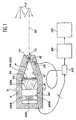
- the device according to the invention of the FIG. 2 is identical to the device of FIG. except in the front part of the device, where find the pinhole in the case of Figure 1.
- the pinhole referenced here 32 is reserved for taking pictures of sources of radiation that we want to locate.
- this pinhole 32 is closed in permanence by a thin patch 33 of light material, opaque to visible light and transparent to gamma radiation.
- Closing the pinhole 32 (opposite the visible light) can also be achieved through a mobile shutter of the kind of the shutter 16 of the figure 1.
- This shutter is then placed between the luminescent screen (not shown in FIG. 2) and the front-part of the device, part-front which is shown in Figure 2.
- the device of Figure 2 includes an optic 34 adapted to take pictures of the area (in visible light) where these sources.
- the pinhole 32 is in a part 36 shielding constituting the wall of the chamber to pinhole 4 and this part 36 is mobile so we can substitute optics 34 when we want to do an image of the area in visible light.
- Such a moving part must be machined with as much accuracy as possible, which is allowed thanks to the progress of machining controlled by computer.
- this part having a shape adapted to exactly complement the body 6 of the device, allows advantageously to obtain the most homogeneous shielding possible around the camera so that the background noise due to parasitic radiation passing through the shielding either as uniform as possible.
- This barrel 38 is rotatable around an axis 40 on either side of which find pinhole 32 and optics 34 and that is parallel to the optical axis 18 of the chamber 4.
- the optic 34 is mounted in a support 42 which is made rigidly attached to the part of shielding 36 via an arm 44.
- the barrel 38 is in the position allowing the taking of images sources of gamma radiation and pinhole 32 is located on the axis 18 of the chamber 4.
- This pinhole is permanently closed by the pastille 33, or by the mobile shutter mentioned more high in the closed position (when such a shutter is planned).
- the movable shutter (in the variant mentioned above) is then in the position open (possibly during the single exposure time chosen by the users).
- the device of Figure 2 is provided with a assembly 48 comprising a motor 50 and a gearbox 52 and fixed by means of a support plate 54 to the front of the body 6 of the device.
- This geared motor assembly 48 is capable to rotate the barrel 38 by via a mechanical axis 56 centered on the axis (geometric) 40.
- the drive mechanism of the barrel 38 as many pieces are made the drive mechanism of the barrel 38 as possible in a light metal such as aluminum.
- FIG. 34 A preferred embodiment of optics 34 is schematically shown in FIG.
- the optic 34 of FIG. lenses 58 and 60 whose common optical axis constitutes the axis 46 of the optics 34.
- These two lenses form a doublet and are separated by a diaphragm 62 of pupil 66.
- these lenses are plano-convex and their convex faces are turned towards each other.
- the optics 34 is positioned so that its focus-image is on the input face of the camera 26, this input face being the common plane to the screen 24 and the reducer 26a.
- Both lenses are designed so to allow focus on the camera 26 or more precisely, on the input side (defined above) from this camera, to get sharp images in visible light.
- the diameter of the pupil 66 that understands the diaphragm 62 is optimized by a compromise between a diameter of great value, to capture a maximum light and reduce the effects of diffraction, and a diameter of small value for ensure a great depth of field.
- the optics or lens is optimized for a depth of field ranging from 1 m to infinity.
- the invention is not limited to use with the optical chain that is shown in Figure 1 and which includes the screen 24 and the camera 26.
- the part of mobile shielding and optics in a two-device sensitive films of the kind that is described in the document (1).
- the film 70 is sensitive only to light visible and the other film 72 is sensitive only to gamma radiation.
Landscapes
- Physics & Mathematics (AREA)
- Health & Medical Sciences (AREA)
- Life Sciences & Earth Sciences (AREA)
- General Physics & Mathematics (AREA)
- High Energy & Nuclear Physics (AREA)
- Molecular Biology (AREA)
- Spectroscopy & Molecular Physics (AREA)
- Measurement Of Radiation (AREA)
- Radiography Using Non-Light Waves (AREA)
Claims (9)
- Vorrichtung zu Lokalisierung in einer Zone befindlicher Strahlungsquellen (2), wobei diese Vorrichtung eine Lochblendenkammer (4), deren Wand eine Abschirmung (6) bildet, welche die genannte Strahlung absorbiert, und Verschlusseinrichtungen (16, 33) dieser Lochblendenkammer (4) umfasst, wobei diese Verschlusseinrichtungen (16, 33) durchlässig sind für die Strahlung der Quellen (2), und diese Vorrichtung außerdem in der Lochblendenkammer (4), dieser Lochblende (32) gegenüberstehend, Bilderzeugungseinrichtungen (24-26, 70-72) umfasst, die ermöglichen, wenn die Verschlusseinrichtungen (16, 33) geöffnet sind, einerseits dank der Strahlung der Quellen ein Bild von diesen herzustellen und andererseits dank des sichtbaren Lichts ein Bild von der genannten Zone,
dabei ist diese Vorrichtung dadurch gekennzeichnet, dass ein die Lochblende (32) umfassender Teil (36) der Abschirmung (6) beweglich ist und starr mit einer Optik (34) verbunden ist, die ermöglicht, mit dem sichtbaren Licht scharfe Bilder in dem gewünschten Schärfenbereich zu erlangen, wobei die Optik (34) den Platz der Lochblende (32) einnehmen kann, um das Bild der Zone herzustellen, und umgekehrt, um das Bild der Quellen (2) herzustellen. - Vorrichtung nach Anspruch 1, bei welcher der bewegliche Teil (36) der Abschirmung (6) und die Optik (34) um eine Achse (40) gedreht werden können, die parallel ist zu der Achse (18) der Kammer (4).
- Vorrichtung nach Anspruch 2, bei welcher der bewegliche Teil (36) der Abschirmung (6) eine Form hat, die genau an die Form der Wand der Lochblendenkammer (4) angepasst ist, wenn die Lochblende 32 sich in der Stellung befindet, welche die Herstellung des Bildes von den Quellen ermöglicht.
- Vorrichtung nach einem der Ansprüche 2 und 3, die außerdem eine Getriebemotoreinheit (48) umfasst, befestigt an der Wand der Kammer (4), außerhalb von dieser, die dazu dient, die durch den beweglichen Teil (36) der Abschirmung (6) und die Optik (34) gebildete Einheit um die zu der Achse (18) der Kammer (4) parallele Achse (40) zu drehen.
- Vorrichtung nach einem der Ansprüche 1 bis 4, bei der die Optik umfasst:zwei Linsen (58, 60), bestimmt zur Fokussierung auf die Bilderzeugungseinrichtungen, undeine Lochblende (62), die zwischen den beiden Linsen angeordnet ist und deren Öffnung (66) so festgelegt ist, dass man den erwünschten Schärfenbereich erhält.
- Vorrichtung nach einem der Ansprüche 1 bis 5, bei der die Verschlusseinrichtungen (16, 33) einen beweglichen Verschluss umfassen, der durchlässig ist für die Strahlung der Quellen (2) und der sich zwischen den Bilderzeugungseinrichtungen (24-26, 70-72) und dem beweglichen Teil (36) der Abschirmung befindet.
- Vorrichtung nach einem der Ansprüche 1 bis 5, bei der die Verschlusseinrichtungen (16, 33) ein Element (33) umfassen, das undurchlässig ist für das sichtbare Licht und durchlässig für die Strahlung der Quellen (2) und das die Lochblende (32) permanent verschließt.
- Vorrichtung nach einem der Ansprüche 1 bis 7, bei der die Bilderzeugungseinrichtungen einen Leuchtschirm (24) umfassen, der im sichtbaren Bereich durchlässig ist und fähig, die Strahlung der Quellen umzuwandeln in eine Strahlung aus sichtbarem Licht, wobei die Verschlusseinrichtungen außerdem fähig sind, das sichtbare Licht der Zone daran zu hindern, den Schirm zu erreichen, und diese Vorrichtung dabei auch eine Kamera (26) umfasst, die optisch mit dem Schirm (24) gekoppelt und fähig ist, dank der Lichtstrahlung, die sie von dem Schirm (24) erhält, in Form von elektrischen Signalen ein Bild der Quellen (2) zu liefern, und dank des sichtbaren Lichts, das sie von der Zone durch den Schirm (24) hindurch erhält, ein Bild von dieser Zone zu liefern, wenn die Verschlusseinrichtungen (16, 33) geöffnet sind.
- Vorrichtung nach einem der Ansprüche 1 bis 7, bei der die Bilderzeugungseinrichtungen eine Vorrichtung mit zwei Filmen (70, 72) umfassen, wobei einer dieser beiden Filme für die Strahlung der Quellen (2) empfindlich ist und der andere für das sichtbare Licht der Zone.
Applications Claiming Priority (3)
| Application Number | Priority Date | Filing Date | Title |
|---|---|---|---|
| FR9712892 | 1997-10-15 | ||
| FR9712892A FR2769717B1 (fr) | 1997-10-15 | 1997-10-15 | Dispositif de localisation de sources de rayonnement |
| PCT/FR1998/002211 WO1999019747A1 (fr) | 1997-10-15 | 1998-10-14 | Dispositif de localisation de sources de rayonnement |
Publications (2)
| Publication Number | Publication Date |
|---|---|
| EP0944845A1 EP0944845A1 (de) | 1999-09-29 |
| EP0944845B1 true EP0944845B1 (de) | 2004-08-25 |
Family
ID=9512251
Family Applications (1)
| Application Number | Title | Priority Date | Filing Date |
|---|---|---|---|
| EP98949067A Expired - Lifetime EP0944845B1 (de) | 1997-10-15 | 1998-10-14 | Vorrichtung zur lokalisierung von strahlungsquellen |
Country Status (8)
| Country | Link |
|---|---|
| US (1) | US6380541B1 (de) |
| EP (1) | EP0944845B1 (de) |
| JP (1) | JP3734838B2 (de) |
| DE (1) | DE69825861T2 (de) |
| FR (1) | FR2769717B1 (de) |
| RU (1) | RU2232405C2 (de) |
| UA (1) | UA46882C2 (de) |
| WO (1) | WO1999019747A1 (de) |
Families Citing this family (16)
| Publication number | Priority date | Publication date | Assignee | Title |
|---|---|---|---|---|
| GB0107551D0 (en) | 2001-03-27 | 2001-05-16 | Matra Bae Dynamics Uk Ltd | Radiation monitor |
| US7286639B2 (en) * | 2003-12-12 | 2007-10-23 | Ge Medical Systems Global Technology Company, Llc | Focal spot sensing device and method in an imaging system |
| US7847260B2 (en) | 2005-02-04 | 2010-12-07 | Dan Inbar | Nuclear threat detection |
| US7820977B2 (en) * | 2005-02-04 | 2010-10-26 | Steve Beer | Methods and apparatus for improved gamma spectra generation |
| US8173970B2 (en) * | 2005-02-04 | 2012-05-08 | Dan Inbar | Detection of nuclear materials |
| FR2884618B1 (fr) * | 2005-04-19 | 2008-06-06 | Commissariat Energie Atomique | Dispositif limitant l'apparition d'artefacts de decodage pour gamma camera a masque code. |
| GB0509974D0 (en) * | 2005-05-16 | 2005-06-22 | Univ Leicester | Imaging device and method |
| WO2007011214A1 (en) * | 2005-07-19 | 2007-01-25 | Milabs B.V. | Radiation detection apparatus |
| FR2932573B1 (fr) * | 2008-06-16 | 2014-09-05 | Commissariat Energie Atomique | Dispositif d'imagerie gamma ameliore permettant la localisation precise de sources irradiantes dans l'espace |
| FR2943143B1 (fr) * | 2009-03-13 | 2012-10-05 | Commissariat Energie Atomique | Dispositif de caracterisation radiologique protege contre des sources de rayonnement ionisant parasites |
| AU2011203186A1 (en) | 2010-07-01 | 2012-01-19 | Aristocrat Technologies Australia Pty Limited | A method of gaming, a gaming system, and a game controller |
| JP2013250108A (ja) * | 2012-05-31 | 2013-12-12 | Hitachi-Ge Nuclear Energy Ltd | 放射線撮像装置、および放射線源の分布画像の作成方法 |
| JP5918093B2 (ja) * | 2012-09-21 | 2016-05-18 | 日立アロカメディカル株式会社 | 放射線測定装置及び放射線測定方法 |
| KR101681130B1 (ko) * | 2014-07-11 | 2016-12-12 | 한국원자력연구원 | 방사선 3차원 탐지 및 가시화 장치 및 방법 |
| CN108535767B (zh) * | 2018-03-27 | 2020-10-09 | 中国原子能科学研究院 | 一种α源成像测量装置 |
| JP2024001833A (ja) * | 2022-06-22 | 2024-01-10 | 能美防災株式会社 | 炎検知システム |
Family Cites Families (10)
| Publication number | Priority date | Publication date | Assignee | Title |
|---|---|---|---|---|
| US3107276A (en) * | 1960-12-23 | 1963-10-15 | Abraham E Cohen | Apparatus for visualizing a nuclear radiation source |
| US4105318A (en) * | 1974-05-30 | 1978-08-08 | Izon Corporation | Pinhole microfiche recorder and viewer |
| US4090080A (en) * | 1976-01-06 | 1978-05-16 | Galileo Electro-Optics Corp. | Imaging |
| US4528453A (en) * | 1982-07-30 | 1985-07-09 | Albert Einstein College Of Medicine Of Yeshiva University | Dual collimator |
| FR2575821B1 (fr) * | 1985-01-04 | 1987-01-30 | Commissariat Energie Atomique | Dispositif de localisation a distance de sources radioactives |
| EP0236790B1 (de) * | 1986-02-28 | 1990-10-17 | Siemens Aktiengesellschaft | Zahnärztliches Röntgendiagnostikgerät zur Erstellung von Panorama-Schichtaufnahmen vom Kiefer eines Patienten |
| FR2652909B1 (fr) * | 1989-10-11 | 1992-03-27 | Commissariat Energie Atomique | Dispositif de localisation en temps reel de sources de rayonnement. |
| US5327291A (en) * | 1992-03-30 | 1994-07-05 | Polaroid Corporation | Compact objective lens |
| FR2717587B1 (fr) * | 1994-03-21 | 1996-04-19 | Commissariat Energie Atomique | Dispositif de localisation en temps réel de sources de rayonnement. |
| US5689376A (en) * | 1995-04-24 | 1997-11-18 | Eastman Kodak Company | Two element optical system, a camera using it and method of making the camera |
-
1997
- 1997-10-15 FR FR9712892A patent/FR2769717B1/fr not_active Expired - Fee Related
-
1998
- 1998-10-14 US US09/319,889 patent/US6380541B1/en not_active Expired - Lifetime
- 1998-10-14 JP JP52119399A patent/JP3734838B2/ja not_active Expired - Fee Related
- 1998-10-14 DE DE69825861T patent/DE69825861T2/de not_active Expired - Lifetime
- 1998-10-14 RU RU99115741/28A patent/RU2232405C2/ru not_active IP Right Cessation
- 1998-10-14 WO PCT/FR1998/002211 patent/WO1999019747A1/fr not_active Ceased
- 1998-10-14 UA UA99074058A patent/UA46882C2/uk unknown
- 1998-10-14 EP EP98949067A patent/EP0944845B1/de not_active Expired - Lifetime
Also Published As
| Publication number | Publication date |
|---|---|
| EP0944845A1 (de) | 1999-09-29 |
| FR2769717B1 (fr) | 1999-12-03 |
| DE69825861T2 (de) | 2005-08-18 |
| JP3734838B2 (ja) | 2006-01-11 |
| US6380541B1 (en) | 2002-04-30 |
| UA46882C2 (uk) | 2002-06-17 |
| JP2001506763A (ja) | 2001-05-22 |
| DE69825861D1 (de) | 2004-09-30 |
| FR2769717A1 (fr) | 1999-04-16 |
| WO1999019747A1 (fr) | 1999-04-22 |
| RU2232405C2 (ru) | 2004-07-10 |
Similar Documents
| Publication | Publication Date | Title |
|---|---|---|
| CA2027286C (fr) | Dispositif de localisation en temps reel de sources de rayonnement | |
| EP0944845B1 (de) | Vorrichtung zur lokalisierung von strahlungsquellen | |
| FR2683328A1 (fr) | Dispositif de reglage de point focal pour objectif zoom. | |
| EP0674188B1 (de) | Vorrichtung zur Echtzeitlokalisierung von Strahlenquellen | |
| WO2002067016A2 (fr) | Dispositif support d"appareil photographique | |
| WO2022128061A1 (fr) | Boite a illumination homogene pour imagerie photographique ou par camera | |
| EP3221688A1 (de) | Linsenloses bildgebungssystem mit einer diode, membran und diffusor zwischen der diode und der membran | |
| EP0032334A1 (de) | Photodetektorvorrichtung zur Erzeugung von Videobildern mit automatischer Empfindlichkeitsregelung | |
| FR2709352A1 (fr) | Barillet d'objectif zoom. | |
| EP2030066B1 (de) | Passives optronisches drei-feld-system | |
| EP1960827B1 (de) | Augenoptisches display | |
| FR2593616A1 (fr) | Bague avec obturateur integre, en particulier pour prise de vues | |
| EP4130867B1 (de) | Verfahren zur erfassung eines bildes von mindestens einem stern und gerät zur durchführung des verfahrens | |
| CA3046174C (fr) | Systeme de detection de rayonnements electromagnetiques | |
| FR2706626A1 (fr) | Dispositif de localisation à distance de sources de rayonnement. | |
| FR3066834A1 (fr) | Procede d'assistance a l'installation d'au moins un occulteur reel pour un detecteur de presence et dispositif associe | |
| WO1999014566A1 (fr) | Procede et dispositif d'imagerie des temperatures d'un corps opaque tres chaud | |
| EP0188973B1 (de) | Vorrichtung zur Fernlokalisierung einer radioaktiven Quelle | |
| FR3143136A1 (fr) | Jumelles de vision nocturne | |
| EP0950909B1 (de) | Lichtsammelndes optisches System, das ein Objektiv mit mehreren Brennweiten bildet | |
| CH626454A5 (en) | Aligned optical device for looking through a chamber wall | |
| FR2977946A1 (fr) | Obturateur pour camera numerique | |
| EP2867716A1 (de) | Vorrichtung zur überwachung der externen umgebung einer plattform, insbesondere einer meeresplattform, periskop und plattform mit solch einer vorrichtung | |
| FR2575858A1 (fr) | Convertisseur d'images a fibres optiques et dispositif de radiographie, chambre a stenope et gamma-camera comprenant un tel convertisseur d'images | |
| BE479250A (de) |
Legal Events
| Date | Code | Title | Description |
|---|---|---|---|
| PUAI | Public reference made under article 153(3) epc to a published international application that has entered the european phase |
Free format text: ORIGINAL CODE: 0009012 |
|
| 17P | Request for examination filed |
Effective date: 19990429 |
|
| AK | Designated contracting states |
Kind code of ref document: A1 Designated state(s): BE CH DE GB IT LI |
|
| GRAP | Despatch of communication of intention to grant a patent |
Free format text: ORIGINAL CODE: EPIDOSNIGR1 |
|
| GRAS | Grant fee paid |
Free format text: ORIGINAL CODE: EPIDOSNIGR3 |
|
| GRAA | (expected) grant |
Free format text: ORIGINAL CODE: 0009210 |
|
| AK | Designated contracting states |
Kind code of ref document: B1 Designated state(s): BE CH DE GB IT LI |
|
| REG | Reference to a national code |
Ref country code: GB Ref legal event code: FG4D Free format text: NOT ENGLISH |
|
| REG | Reference to a national code |
Ref country code: CH Ref legal event code: EP |
|
| REF | Corresponds to: |
Ref document number: 69825861 Country of ref document: DE Date of ref document: 20040930 Kind code of ref document: P |
|
| RAP2 | Party data changed (patent owner data changed or rights of a patent transferred) |
Owner name: COMPAGNIE GENERALE DES MATIERES NUCLEAIRES Owner name: COMMISSARIAT A L'ENERGIE ATOMIQUE |
|
| GBT | Gb: translation of ep patent filed (gb section 77(6)(a)/1977) |
Effective date: 20050112 |
|
| PLBE | No opposition filed within time limit |
Free format text: ORIGINAL CODE: 0009261 |
|
| STAA | Information on the status of an ep patent application or granted ep patent |
Free format text: STATUS: NO OPPOSITION FILED WITHIN TIME LIMIT |
|
| 26N | No opposition filed |
Effective date: 20050526 |
|
| PGFP | Annual fee paid to national office [announced via postgrant information from national office to epo] |
Ref country code: IT Payment date: 20151014 Year of fee payment: 18 Ref country code: GB Payment date: 20151019 Year of fee payment: 18 Ref country code: DE Payment date: 20151014 Year of fee payment: 18 Ref country code: CH Payment date: 20151007 Year of fee payment: 18 |
|
| PGFP | Annual fee paid to national office [announced via postgrant information from national office to epo] |
Ref country code: BE Payment date: 20151029 Year of fee payment: 18 |
|
| PG25 | Lapsed in a contracting state [announced via postgrant information from national office to epo] |
Ref country code: BE Free format text: LAPSE BECAUSE OF NON-PAYMENT OF DUE FEES Effective date: 20161031 |
|
| REG | Reference to a national code |
Ref country code: DE Ref legal event code: R119 Ref document number: 69825861 Country of ref document: DE |
|
| REG | Reference to a national code |
Ref country code: CH Ref legal event code: PL |
|
| GBPC | Gb: european patent ceased through non-payment of renewal fee |
Effective date: 20161014 |
|
| PG25 | Lapsed in a contracting state [announced via postgrant information from national office to epo] |
Ref country code: GB Free format text: LAPSE BECAUSE OF NON-PAYMENT OF DUE FEES Effective date: 20161014 Ref country code: DE Free format text: LAPSE BECAUSE OF NON-PAYMENT OF DUE FEES Effective date: 20170503 Ref country code: LI Free format text: LAPSE BECAUSE OF NON-PAYMENT OF DUE FEES Effective date: 20161031 Ref country code: CH Free format text: LAPSE BECAUSE OF NON-PAYMENT OF DUE FEES Effective date: 20161031 |
|
| PG25 | Lapsed in a contracting state [announced via postgrant information from national office to epo] |
Ref country code: IT Free format text: LAPSE BECAUSE OF NON-PAYMENT OF DUE FEES Effective date: 20161014 |
|
| REG | Reference to a national code |
Ref country code: BE Ref legal event code: MM Effective date: 20161031 |