EP0944862B1 - Umformer von mechanischer in elektrische energie und zeitmessvorrichtung damit - Google Patents
Umformer von mechanischer in elektrische energie und zeitmessvorrichtung damit Download PDFInfo
- Publication number
- EP0944862B1 EP0944862B1 EP97946010A EP97946010A EP0944862B1 EP 0944862 B1 EP0944862 B1 EP 0944862B1 EP 97946010 A EP97946010 A EP 97946010A EP 97946010 A EP97946010 A EP 97946010A EP 0944862 B1 EP0944862 B1 EP 0944862B1
- Authority
- EP
- European Patent Office
- Prior art keywords
- rotor
- fact
- generator
- converter
- converter according
- Prior art date
- Legal status (The legal status is an assumption and is not a legal conclusion. Google has not performed a legal analysis and makes no representation as to the accuracy of the status listed.)
- Expired - Lifetime
Links
Images



Classifications
-
- H—ELECTRICITY
- H02—GENERATION; CONVERSION OR DISTRIBUTION OF ELECTRIC POWER
- H02K—DYNAMO-ELECTRIC MACHINES
- H02K7/00—Arrangements for handling mechanical energy structurally associated with dynamo-electric machines, e.g. structural association with mechanical driving motors or auxiliary dynamo-electric machines
- H02K7/18—Structural association of electric generators with mechanical driving motors, e.g. with turbines
- H02K7/1807—Rotary generators
- H02K7/1853—Rotary generators driven by intermittent forces
-
- G—PHYSICS
- G04—HOROLOGY
- G04C—ELECTROMECHANICAL CLOCKS OR WATCHES
- G04C10/00—Arrangements of electric power supplies in time-pieces
-
- H—ELECTRICITY
- H02—GENERATION; CONVERSION OR DISTRIBUTION OF ELECTRIC POWER
- H02K—DYNAMO-ELECTRIC MACHINES
- H02K16/00—Machines with more than one rotor or stator
Definitions
- the present invention relates to a mechanical energy converter in electrical energy and the timepieces using these converters.
- Portable electrical devices, as well as timepieces quartz electronics mainly use, as an energy source, batteries or accumulators.
- the major drawback of these lies in their limited lifespan. It is therefore interesting to replace these sources of electrical energy by a mechanical energy source and a converter from mechanical energy to electrical energy.
- Patent DE 3903706 describes a watch comprising a movement electronic with a display and a generator driven by a spring motor.
- patent EP 0695978 describes a means of indicating the time using a spring as a source of energy and comprising a generator driven by the spring and electronic force-operated control means generator electromotive.
- the object of the present invention is to remedy the disadvantages mentioned above by proposing a new type of converter as defined in claim 1.
- FIG. 1 shows a first example of execution of the converter according to the invention.
- This converter has a toothed wheel 11 rotating under the effect of a mechanical energy source, an oscillating mass, either a barrel spring.
- the toothed wheel 11 drives the pinion 12, integral with rotor 13, with a generator electromagnetic.
- This rotor made up of a magnet permanent cylindrical, is housed in a shaped air gap practically cylindrical, arranged in a stator in ferro-nickel material.
- the flux created by the rotor is coupled with the coil 15 of the generator.
- On the surface cylindrical of the stator air gap we create two semicircular openings 16a and 16b for the purpose of give the rotor a reluctant magnetic torque.
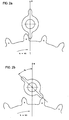
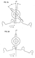
- Figure 2 shows the respective positions of the generator rotor as a function of that of the gear wheel 11.
- the pinion of the generator rotor is located between teeth 1 and 2 of the toothed wheel, the the latter exerting no torque on the rotor.
- the rotor under the effect of the magnetic reluctant couple, is positioned along the axis R.
- the toothed wheel 11 turning clockwise, drives the generator rotor pinion and deviates it by an angle ⁇ 0 from its original position.
- the tooth 2 of the toothed wheel no longer in engagement with the generator rotor pinion, the rotor unhooks and oscillates around its rest position, i.e.
- the axis R under the action of the magnetic reluctant couple. Being given the very low inertia of the rotor, the latter can achieve very high angular velocities (velocity angular exceeding 600rad / sec).
- the oscillating movement at high frequency of the rotor makes it possible to obtain at the terminals of the generator coil 15 an induced voltage level Student.
- the mechanical-electrical converter according to the invention makes it possible to obtain an instantaneous high speed of the generator rotor from a low speed gear average and without gear train speed multiplier.
- the generator is only subject to its own mechanical losses, the rotor being free, which provides a high overall yield.
- Figure 3 shows a second example of the converter according to the invention.
- the toothed wheel 31 simultaneously engages the rotors 33a and 33b thanks to the pinions 32a, respectively 32b.
- the respective rest positions of the rotors are offset by so that the change in total reaction torque on wheel 31 is minimal.
- Figure 4 shows a first example of use of the converter according to the invention.
- barrel spring 40 provides energy mechanical to converter through the wheel of transmission 41; the induced voltage across the coil 45 of the converter is rectified and multiplied to using rectifier 46.
- the transformed electrical energy is then stored in capacities C1 and C2. This energy can be used by an electrical appliance shown as a load resistance Rc.
- FIG. 5 shows a second example of use of the converter according to the invention.
- the energy source 50 composed of a barrel spring, distributes mechanical energy through the cogs 51.
- Display means 52 generally formed of needles, are mechanically linked to the gear wheels 51.
- the cogs 51 also drive converter 53, which supplies electrical power to rectifier 54, which stores this energy in capacity C. Energy stored serves to power the control member 56 and speed measuring means 55.
- the brake electromagnetic 57 the braking torque of which is adjusted by the control member 56 as a function of the speed average rotation of the cog allows to regulate this last.
- FIG. 6 represents an example of execution of the electromagnetic brake.
- This brake consists of a magnetic circuit 61 made of ferromagnetic material, a permanent magnet rotor 62 of cylindrical shape, a coil 63 coupled with the flux created by the rotor 62.
- the terminals of the coil 63 are connected with a braking resistor network 64.
- the actual value braking resistor can be adjusted by switches controlled by control signals from block 65, which allows to modify the torque braking exerted on the rotor 62.
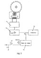
- FIG. 7 represents an example of execution of the device for measuring the average rotation speed of transmission wheels of the converter according to the invention.
- This device includes a measurement circuit 71 of the voltage across the generator; this tension, varying strongly each time the rotor pinion is removed of the generator according to the explanations relating to the figures 2a, 2b, 2c, and 2d, is provided at the input of the circuit comparison 72 which compares it with a voltage of reference Uref.
- the output of circuit 72 delivers a signal level 1 or 0 logic depending on whether the measured voltage is greater than or less than the reference voltage. This logic signal allows the counter 73 to determine the duration between two recesses of the rotor pinion, i.e.
- Time base 74 including a crystal oscillator, shaping circuits and divider, supplies the clock signal CK to the counter 73.
- This time base is supplied with energy electric by the capacity C of block 54 of FIG. 5.
- time base 74 is not supplied with permanently but only during the measurement phase of average speed, control of the time base being supplied by switch 17.
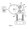
- the third embodiment of the converter illustrated in Figure 8 has a toothed wheel 61 mechanically driven by a barrel or a mass offset and meshing with the pinions 62a, 62b of two rotors 63a, 63b housed in the same stator 64 comprising two legs 64a, 64b around which the coils 65a, 65b.
Landscapes
- Engineering & Computer Science (AREA)
- Power Engineering (AREA)
- Physics & Mathematics (AREA)
- General Physics & Mathematics (AREA)
- Connection Of Motors, Electrical Generators, Mechanical Devices, And The Like (AREA)
- Electromechanical Clocks (AREA)
- Iron Core Of Rotating Electric Machines (AREA)
Claims (13)
- Umformer von mechanischer in elektrische Energie mit einem Übertragungsorgan für mechanische Energie, bestehend aus zumindest einem Zahnrad (11), aus einem Organ für die Umformung von mechanischer Energie in elektrische Energie, das aus zumindest einem elektromagnetischen Generator zusammengesetzt ist, der zumindest einen Rotor (13) aufweist, der durch dieses Übertragungsorgan für mechanische Energie angetrieben wird, dadurch gekennzeichnet, dass jeder Rotor (13) jedes elektromagnetischen Generators ein Positioniermoment besitzt, das seine Gleichgewichts-Ruhelage in Abwesenheit äusserer Momente bestimmt, dadurch, dass der Antrieb des oder der Rotoren (13) durch das Übertragungsorgan für mechanische Energie nur über einen begrenzten Winkel á0 des Rotors (13) aktiv ist, so dass der oder die Rotoren (13) keine ganze Umdrehung ausführen können, sondern um ihre Gleichgewichts-Ruhelage oszillieren.
- Energieumformer nach Anspruch 1, dadurch gekennzeichnet, dass er Mittel (46) für die Gleichrichtung und Vervielfachung der Spannung des Generators sowie Mittel (C) für die Speicherung der durch den Generator erzeugten elektrischen Energie enthält.
- Energieumformer nach Anspruch 1 oder nach Anspruch 2, dadurch gekennzeichnet, dass der Generator aus einem Rotor (13) mit Permanentmagneten, einem magnetischen Kreis (14) aus weichmagnetischem Material und einer mit dem durch den Magneten des Rotors (13) erzeugten Fluss gekoppelten Spule (15) besteht.
- Umformer nach einem der Ansprüche 1 bis 3, dadurch gekennzeichnet, dass der Antrieb des Rotors (13) durch das Übertragungsorgan für mechanische Energie (11) diskontinuierlich ist, wobei dieses Übertragungsorgan den Rotor aus seiner Ruhelage herausführt; und dadurch, dass der Rotor (13), sobald seine mechanische Antriebsverbindung unterbrochen ist, in seine Ruhelage zurückkehrt, während er unter der Einwirkung des Reluktanzmoments des Umformers mit hoher Geschwindigkeit um diese Lage herum oszilliert.
- Umformer nach Anspruch 4, dadurch gekennzeichnet, dass die Erzeugung elektrischer Energie während der freien Oszillationen des Rotors (13) erfolgt.
- Umformer nach Anspruch 5, dadurch gekennzeichnet, dass das Zahnrad (11) mit einem Antriebsrad mit zwei Zähnen (12) in Eingriff kommt, die fest mit jedem Rotor (13) verbunden sind.
- Umformer nach Anspruch 5, dadurch gekennzeichnet, dass er zwei Generatoren enthält, deren Rotoren (33a, b) durch das gleiche Zahnrad (31) angetrieben werden.
- Umformer nach Anspruch 5 oder Anspruch 6, dadurch gekennzeichnet, dass jeder Generator mehrere Rotoren (33) umfasst, die mit dem gleichen Zahnrad (31) in Eingriff kommen.
- Elektrogerät mit einem Energieumformer nach Ansprüchen 1 bis 8.
- Elektrogerät nach Anspruch 9, aus einer Uhr bestehend, die eine Zugfeder (50) enthält, die mit dem Übertragungsorgan für mechanische Energie (51) des Umformers gekoppelt ist, ferner Mittel, um eine Zeitbasis zur Verfügung zu stellen, Mittel (55), um die mittlere Drehgeschwindigkeit der Räder für die Übertragung der mechanischen Energie zu messen, Mittel (57), um die mittlere Drehgeschwindigkeit der Übertragungsräder zu regulieren, Mittel, um die mittlere Geschwindigkeit der Übertragungsräder anzuzeigen, dadurch gekennzeichnet, dass diese Mittel zur Regulierung der mittleren Drehgeschwindigkeit aus einer elektromagnetischen Bremse (57) bestehen, deren Bremsmoment durch ein Steuerorgan (56) in Abhängigkeit von einer Sollgeschwindigkeit geregelt wird.
- Elektrogerät nach Anspruch 9 oder Anspruch 10, worin die elektromagnetische Bremse aus einem Rotor mit Permanentmagneten, einem magnetischen Kreis aus weichmagnetischem Material und einer mit dem durch den Magneten des Rotors erzeugten Fluss gekoppelten Spule besteht, dadurch gekennzeichnet, dass das mittlere Bremsmoment durch ein Steuerorgan in Abhängigkeit von einer Sollgeschwindigkeit reguliert wird, indem die Anschlussklemmen der Bremsspule mit einem Widerstand verbunden werden, dessen Grösse variiert werden kann.
- Elektrogerät nach Anspruch 9 oder Anspruch 10, dadurch gekennzeichnet, dass das Organ (55) für die Messung der mittleren Drehgeschwindigkeit der Übertragungsräder einen Messkreis (71) für die Spannung an den Klemmen des Generators, einen Schaltkreis (72) für den Vergleich der gemessenen Spannung mit einer Bezugsspannung (Uref), der ein logisches Signal des Niveaus 1, wenn die gemessene Spannung die Bezugsspannung übersteigt, und im umgekehrten Falle ein logisches Signal des Niveaus 0 an seinem Ausgang liefert, sowie einen Zählkreis (73) umfasst, der es ermöglicht, die Zeit zwischen zwei aufeinanderfolgenden Übergängen des logischen Signals vom Niveau 0 zum Niveau 1 zu bestimmen.
- Elektrogerät nach Anspruch 12, worin dieser Zählkreis (73) eine Zeitbasis (74) enthält, die aus einem Quarzoszillator, einer Impulsschaltung und einer Teilerschaltung besteht, dadurch gekennzeichnet, dass die Zeitbasis (74) nicht dauernd, sondern nur während der Phase der Messung der mittleren Drehgeschwindigkeit der Energieübertragungsräder aktv ist.
Applications Claiming Priority (3)
| Application Number | Priority Date | Filing Date | Title |
|---|---|---|---|
| CH310096 | 1996-12-18 | ||
| CH03100/96A CH689469A5 (fr) | 1996-12-18 | 1996-12-18 | Convertisseur d'énergie mécano-électrique et pièce d'horlogerie comportant un tel convertisseur d'énergie. |
| PCT/IB1997/001569 WO1998027473A1 (fr) | 1996-12-18 | 1997-12-16 | Convertisseur d'energie mecano-electrique et piece d'horlogerie comportant un tel convertisseur d'energie |
Publications (2)
| Publication Number | Publication Date |
|---|---|
| EP0944862A1 EP0944862A1 (de) | 1999-09-29 |
| EP0944862B1 true EP0944862B1 (de) | 2004-01-28 |
Family
ID=4248626
Family Applications (1)
| Application Number | Title | Priority Date | Filing Date |
|---|---|---|---|
| EP97946010A Expired - Lifetime EP0944862B1 (de) | 1996-12-18 | 1997-12-16 | Umformer von mechanischer in elektrische energie und zeitmessvorrichtung damit |
Country Status (7)
| Country | Link |
|---|---|
| US (1) | US6041022A (de) |
| EP (1) | EP0944862B1 (de) |
| JP (1) | JP3969747B2 (de) |
| AU (1) | AU5131498A (de) |
| CH (1) | CH689469A5 (de) |
| DE (1) | DE69727397T2 (de) |
| WO (1) | WO1998027473A1 (de) |
Families Citing this family (18)
| Publication number | Priority date | Publication date | Assignee | Title |
|---|---|---|---|---|
| US20070205881A1 (en) * | 2000-09-08 | 2007-09-06 | Automotive Technologies International, Inc. | Energy Harvesting Systems and Methods for Vehicles |
| CN1132071C (zh) * | 1997-09-26 | 2003-12-24 | 精工爱普生株式会社 | 电子控制式机械钟表 |
| JP2001067897A (ja) * | 1999-08-31 | 2001-03-16 | Mitsubishi Electric Corp | 半導体記憶装置およびそれを用いた半導体テスト方法 |
| DE10125059C5 (de) * | 2001-05-22 | 2016-07-21 | Enocean Gmbh | Induktiver Spannungsgenerator |
| CA2414640A1 (en) * | 2002-12-18 | 2004-06-18 | Beaver Machine Corporation | Electrical generator for a coin mechanism and coin mechanism with an electrical generator and metal detection and release system |
| EP1603087A1 (de) * | 2004-01-15 | 2005-12-07 | Beaver Machine Corporation | Elektrischer Generator für Münzgeräte und System für Metalldetektion und Abgabe von Münzen. |
| US20070242406A1 (en) * | 2006-04-17 | 2007-10-18 | Annis Theodore C | Electricity generating apparatus utilizing a single magnetic flux path |
| US8258644B2 (en) * | 2009-10-12 | 2012-09-04 | Kaplan A Morris | Apparatus for harvesting energy from flow-induced oscillations and method for the same |
| CN101924451B (zh) * | 2010-07-30 | 2013-05-01 | 安徽大学 | 易于集成制造的高性能微型电磁式振动能量采集器 |
| CN104054231A (zh) * | 2011-11-21 | 2014-09-17 | 摩西·英迪格 | 通过随机运动操作的电动机 |
| FR2987517B1 (fr) * | 2012-02-27 | 2015-02-20 | Ilsa | Dispositif de commande programmee d'un appareil electrique, notamment diffuseur de parfum |
| CH707340A2 (fr) * | 2012-12-11 | 2014-06-13 | Richemont Internat Ltd | Organe régulateur pour montre-bracelet. |
| CN105375685A (zh) * | 2015-11-03 | 2016-03-02 | 上海应用技术学院 | 自动门发电装置 |
| US20170364038A1 (en) * | 2016-06-15 | 2017-12-21 | Yehuda Fulda | Kinetic Powered Smartwatch |
| JP6908830B2 (ja) * | 2017-04-28 | 2021-07-28 | ミツミ電機株式会社 | 発電装置および電子デバイス |
| CN112751458B (zh) * | 2019-10-21 | 2022-08-12 | 德能森智能科技(成都)有限公司 | 一种用于自发电装置的自发电方法及装置 |
| CN112865423B (zh) * | 2019-10-21 | 2022-08-12 | 德能森智能科技(成都)有限公司 | 一种无线无源装置的发电组件及发电方法 |
| EP3944027B1 (de) * | 2020-07-21 | 2024-06-05 | The Swatch Group Research and Development Ltd | Tragbares gerät, insbesondere armbanduhr, das mit einer stromquellevorrichtung mit einem elektromechanischen wandler ausgestattet ist |
Family Cites Families (12)
| Publication number | Priority date | Publication date | Assignee | Title |
|---|---|---|---|---|
| US2791732A (en) * | 1953-04-30 | 1957-05-07 | Rca Corp | Vibratory motor for an electric watch |
| FR92782E (fr) * | 1965-10-13 | 1968-12-27 | Massiot Philips Sa | Stimulateur cardiaque. |
| JPS52127091A (en) * | 1976-04-16 | 1977-10-25 | Seiko Instr & Electronics Ltd | Portable generator |
| JPS5833417Y2 (ja) * | 1977-05-06 | 1983-07-26 | 松下電器産業株式会社 | 高電圧発生装置 |
| CH621460B (fr) * | 1977-12-23 | Ebauches Electroniques Sa | Piece d'horlogerie electronique avec transducteur electroacoustique. | |
| NL8402113A (nl) * | 1984-07-03 | 1986-02-03 | Kinetron Bv | Stelsel voor elektrische voeding van draagbare miniatuur-energieverbruikers. |
| KR950001429Y1 (ko) * | 1988-01-25 | 1995-03-06 | 세이꼬 엡슨 가부시끼가이샤 | 발전장치 부착 전자 팔목시계 |
| DE3903706A1 (de) * | 1988-02-09 | 1989-08-17 | Fraunhofer Ges Forschung | Uhr mit einem elektronischen uhrenbaustein |
| US4853580A (en) * | 1988-08-05 | 1989-08-01 | Tektronix, Inc. | Piezoelectric pulse generator |
| CH687287B5 (fr) * | 1994-01-26 | 1997-05-15 | Roberto Zafferri | Dispositif de production de l'energie necessaire a la marche d'une montre electronique et montre comprenant un tel dispositif. |
| JP3174245B2 (ja) * | 1994-08-03 | 2001-06-11 | セイコーインスツルメンツ株式会社 | 電子制御時計 |
| JPH09205781A (ja) * | 1995-02-01 | 1997-08-05 | Seiko Epson Corp | 圧電体発電装置及びこれを備えた携帯型電力供給装置、携帯型電子機器 |
-
1996
- 1996-12-18 CH CH03100/96A patent/CH689469A5/fr not_active IP Right Cessation
-
1997
- 1997-12-16 JP JP52749998A patent/JP3969747B2/ja not_active Expired - Fee Related
- 1997-12-16 EP EP97946010A patent/EP0944862B1/de not_active Expired - Lifetime
- 1997-12-16 US US09/319,988 patent/US6041022A/en not_active Expired - Fee Related
- 1997-12-16 DE DE69727397T patent/DE69727397T2/de not_active Expired - Lifetime
- 1997-12-16 WO PCT/IB1997/001569 patent/WO1998027473A1/fr not_active Ceased
- 1997-12-16 AU AU51314/98A patent/AU5131498A/en not_active Abandoned
Also Published As
| Publication number | Publication date |
|---|---|
| JP3969747B2 (ja) | 2007-09-05 |
| CH689469A5 (fr) | 1999-04-30 |
| JP2001507557A (ja) | 2001-06-05 |
| US6041022A (en) | 2000-03-21 |
| EP0944862A1 (de) | 1999-09-29 |
| DE69727397D1 (de) | 2004-03-04 |
| WO1998027473A1 (fr) | 1998-06-25 |
| AU5131498A (en) | 1998-07-15 |
| DE69727397T2 (de) | 2004-11-11 |
Similar Documents
| Publication | Publication Date | Title |
|---|---|---|
| EP0944862A1 (de) | Umformer von mechanischer in elektrische energie und zeitmessvorrichtung damit | |
| EP2044490B1 (de) | Elektromechanische hemmungseinrichtung und diese einrichtung benutzender uhrenteil | |
| JPH0769440B2 (ja) | 発電機 | |
| JP6437067B2 (ja) | 自動巻き式腕時計 | |
| EP0580447A1 (de) | Ultraschallmotor und elektronisches Gerät, das mit diesem ausgerüstet ist | |
| US12169391B2 (en) | Wearable object, in particular watch bracelet, comprising a power supply device provided with an electromechanical converter | |
| FR2522448A1 (fr) | Moteur pas-a-pas | |
| EP0393605B1 (de) | Elektronisches Zeitmessgerät mit mindestens zwei Motoren | |
| WO1999049556A1 (fr) | Convertisseur d'energie mecanique en energie electrique et appareil electronique muni d'un tel convertisseur | |
| US7307922B2 (en) | Stopwatch and watch | |
| US5151886A (en) | Analog electric timepiece using an intermittent driving signal | |
| JPH058397B2 (de) | ||
| KR100321491B1 (ko) | 시계내에기계적에너지원과전기적에너지발전기사이의연결장치 | |
| EP0982846B1 (de) | Verfahren und Vorrichtung zur Regelung eines Schrittmotors | |
| EP0155661B1 (de) | Regelschaltung für einen Schrittmotor | |
| EP1426837B1 (de) | Uhrwerk mit Gangreserveanzeige | |
| FR2530030A1 (fr) | Dispositif tachymetrique commande electroniquement | |
| EP0388491A1 (de) | Elektronische Anzeigevorrichtung und Verfahren davon | |
| EP0848306B1 (de) | Zeitmessgerät mit einem Generator zur Erzeugung elektrischer Energie | |
| CH695400A5 (fr) | Pièce d'horlogerie comportant un mouvement avec un générateur d'électricité. | |
| JP3711766B2 (ja) | メトロノーム | |
| CH717674A2 (fr) | Objet portable, notamment montre bracelet, comprenant un dispositif d'alimentation muni d'un convertisseur électromécanique. | |
| CH718652A2 (fr) | Mouvement horloger comprenant une génératrice. | |
| CH320822A (fr) | Installation motrice pour l'entraînement d'un mouvement d'horlogerie | |
| BE465554A (de) |
Legal Events
| Date | Code | Title | Description |
|---|---|---|---|
| PUAI | Public reference made under article 153(3) epc to a published international application that has entered the european phase |
Free format text: ORIGINAL CODE: 0009012 |
|
| 17P | Request for examination filed |
Effective date: 19990604 |
|
| AK | Designated contracting states |
Kind code of ref document: A1 Designated state(s): CH DE FR GB IT LI |
|
| 17Q | First examination report despatched |
Effective date: 20020905 |
|
| GRAH | Despatch of communication of intention to grant a patent |
Free format text: ORIGINAL CODE: EPIDOS IGRA |
|
| RAP1 | Party data changed (applicant data changed or rights of an application transferred) |
Owner name: PATEK PHILIPPE S.A. |
|
| GRAS | Grant fee paid |
Free format text: ORIGINAL CODE: EPIDOSNIGR3 |
|
| GRAA | (expected) grant |
Free format text: ORIGINAL CODE: 0009210 |
|
| AK | Designated contracting states |
Kind code of ref document: B1 Designated state(s): CH DE FR GB IT LI |
|
| REG | Reference to a national code |
Ref country code: GB Ref legal event code: FG4D Free format text: NOT ENGLISH |
|
| REG | Reference to a national code |
Ref country code: CH Ref legal event code: EP |
|
| REG | Reference to a national code |
Ref country code: CH Ref legal event code: NV Representative=s name: MICHELI & CIE INGENIEURS-CONSEILS |
|
| REF | Corresponds to: |
Ref document number: 69727397 Country of ref document: DE Date of ref document: 20040304 Kind code of ref document: P |
|
| GBT | Gb: translation of ep patent filed (gb section 77(6)(a)/1977) |
Effective date: 20040324 |
|
| PLBE | No opposition filed within time limit |
Free format text: ORIGINAL CODE: 0009261 |
|
| STAA | Information on the status of an ep patent application or granted ep patent |
Free format text: STATUS: NO OPPOSITION FILED WITHIN TIME LIMIT |
|
| 26N | No opposition filed |
Effective date: 20041029 |
|
| REG | Reference to a national code |
Ref country code: CH Ref legal event code: PFA Owner name: PATEK, PHILIPPE SA Free format text: PATEK PHILIPPE S.A.#141, CHEMIN DU PONT-DU-CENTENAIRE#1228 PLAN-LES-OUATES (CH) -TRANSFER TO- PATEK, PHILIPPE SA#41, RUE DU RHOENE#1204 GENEVE (CH) |
|
| REG | Reference to a national code |
Ref country code: FR Ref legal event code: RM |
|
| REG | Reference to a national code |
Ref country code: CH Ref legal event code: PFA Owner name: PATEK PHILIPPE SA GENEVE Free format text: PATEK, PHILIPPE SA#41, RUE DU RHONE#1204 GENEVE (CH) -TRANSFER TO- PATEK PHILIPPE SA GENEVE#RUE DU RHONE 41#1204 GENEVE (CH) |
|
| REG | Reference to a national code |
Ref country code: FR Ref legal event code: CD |
|
| PGFP | Annual fee paid to national office [announced via postgrant information from national office to epo] |
Ref country code: GB Payment date: 20101221 Year of fee payment: 14 |
|
| PGFP | Annual fee paid to national office [announced via postgrant information from national office to epo] |
Ref country code: CH Payment date: 20111121 Year of fee payment: 15 Ref country code: FR Payment date: 20120105 Year of fee payment: 15 |
|
| PGFP | Annual fee paid to national office [announced via postgrant information from national office to epo] |
Ref country code: DE Payment date: 20111222 Year of fee payment: 15 |
|
| PGFP | Annual fee paid to national office [announced via postgrant information from national office to epo] |
Ref country code: IT Payment date: 20111229 Year of fee payment: 15 |
|
| REG | Reference to a national code |
Ref country code: CH Ref legal event code: PL |
|
| GBPC | Gb: european patent ceased through non-payment of renewal fee |
Effective date: 20121216 |
|
| REG | Reference to a national code |
Ref country code: FR Ref legal event code: ST Effective date: 20130830 |
|
| REG | Reference to a national code |
Ref country code: DE Ref legal event code: R119 Ref document number: 69727397 Country of ref document: DE Effective date: 20130702 |
|
| PG25 | Lapsed in a contracting state [announced via postgrant information from national office to epo] |
Ref country code: CH Free format text: LAPSE BECAUSE OF NON-PAYMENT OF DUE FEES Effective date: 20121231 Ref country code: DE Free format text: LAPSE BECAUSE OF NON-PAYMENT OF DUE FEES Effective date: 20130702 Ref country code: LI Free format text: LAPSE BECAUSE OF NON-PAYMENT OF DUE FEES Effective date: 20121231 |
|
| PG25 | Lapsed in a contracting state [announced via postgrant information from national office to epo] |
Ref country code: GB Free format text: LAPSE BECAUSE OF NON-PAYMENT OF DUE FEES Effective date: 20121216 Ref country code: FR Free format text: LAPSE BECAUSE OF NON-PAYMENT OF DUE FEES Effective date: 20130102 |
|
| PG25 | Lapsed in a contracting state [announced via postgrant information from national office to epo] |
Ref country code: IT Free format text: LAPSE BECAUSE OF NON-PAYMENT OF DUE FEES Effective date: 20121216 |