EP0944863B1 - Controleur pour la commande de plusieurs dispositifs electriques differents - Google Patents
Controleur pour la commande de plusieurs dispositifs electriques differents Download PDFInfo
- Publication number
- EP0944863B1 EP0944863B1 EP97919061A EP97919061A EP0944863B1 EP 0944863 B1 EP0944863 B1 EP 0944863B1 EP 97919061 A EP97919061 A EP 97919061A EP 97919061 A EP97919061 A EP 97919061A EP 0944863 B1 EP0944863 B1 EP 0944863B1
- Authority
- EP
- European Patent Office
- Prior art keywords
- starter
- logic circuit
- motor
- logical
- connection
- Prior art date
- Legal status (The legal status is an assumption and is not a legal conclusion. Google has not performed a legal analysis and makes no representation as to the accuracy of the status listed.)
- Expired - Lifetime
Links
Images
Classifications
-
- G—PHYSICS
- G05—CONTROLLING; REGULATING
- G05B—CONTROL OR REGULATING SYSTEMS IN GENERAL; FUNCTIONAL ELEMENTS OF SUCH SYSTEMS; MONITORING OR TESTING ARRANGEMENTS FOR SUCH SYSTEMS OR ELEMENTS
- G05B19/00—Program-control systems
- G05B19/02—Program-control systems electric
- G05B19/04—Program control other than numerical control, i.e. in sequence controllers or logic controllers
- G05B19/042—Program control other than numerical control, i.e. in sequence controllers or logic controllers using digital processors
Definitions
- the invention relates to an electric motor starter for starting motors rotating at synchronous speed.
- the electric motor starter of the invention is particularly suited to be used as a controller of electric motors and in that case to replace an ON/OFF-starter controlling an electric motor.
- the controller is not, however, suitable for starting motors whose speed of rotation is controlled linearly, such as controlled by an inverter, but it is only intended for motors rotating at a so-called synchronous speed which speed is thus dependent on the frequency of the supplying electrical network.
- Electric motor starters There are various types of electric motor starters depending on the structure of the electric motor to be controlled and their purpose of use and they comprise an equipment adapted for the electric motor to be started at each time, such as a switching contactor according to the power/current of the motor, and a thermal relay. Starters of a single-speed electric motor, of a two-speed electric motor with two windings, of a dahlander-connected motor, of a star/delta connected motor and the like could be mentioned as various starter and motor types.
- the different operating modes of motors cause dimensioning and installation problems and connection errors as it is not always exactly known at the beginning of planning what kind of a motor is to be used and how the motor will be logically controlled and which additional devices/components are needed in addition to the motor to make the system to be controlled to operate correctly.
- Installation, planning, drafting and testing of such an ordinary motor starter built of discrete parts contactors, thermal relays, time relays, switches, push-button switches, lines, etc.
- the typically used components are components controlled by the mains current, such as relays and contactors, in which case the conductors intended for the main voltage and a suitable installation manner have to be used in their supply and control lines.
- logic circuits are also used in motor starters.
- Such starters are known e.g. from U.S. 5,206,572 and GB 2,206,423. They disclose solutions where the logical connection required for controlling the motor is achieved by means of semiconductor circuits. When such constructions are used, the logical connection has to be planned and either built of discrete components or programmed separately for each programmable logic circuit for each different purpose and motor type. When the motor type or the control mode of the motor changes, either the discrete components or the connection between them have to be changed or a new program has to be developed and a program thereof has to be stored in the case of a programmable logic circuit.
- the motor starters based on the use of logic circuits, described in the references cited, are therefore tailored for the purpose and it is relatively difficult to carry out changes.
- the object of the present invention is to introduce a electric starter according to claim 1.
- the type or the control mode of the electric motor need not be known in advance but the operation or logical motor starter connection to be used can be selected only after installation by a very simple practical procedure.
- the means for selecting for use some motor starter connection stored in the logic circuit can comprise a code switch, such as a HEX switch, and a decoder for providing a selection signal for the logic circuit to make it select for use the required logical motor starter connection. If the starter of the invention is under the control of a more extensive logic system, the means for selecting for use some motor starter connection stored in the logic circuit comprise a logic system controlling the starter, such as a programmable logic controller or a general-purpose computer.
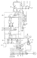
- an electric motor M which is supplied by a three-phase network comprising phases L1, L2 and L3. From this network, the electric current is connected to the motor M, which in the described case is a three-phase and single-winding electric motor, via a main switch Q1, a switching contactor K1 controlled by a motor starter and a thermal relay F1. All these components have three phases.
- the present invention relates in particular to a motor starter controlling the switching contactor K1.
- the motor starter of the invention comprises a logic circuit 10 to which is pre-programmed various logical control connections intended to control various electric motors and possibly to provide different modes of use.
- Such starter types are starters of a single-speed electric motor, of a dahlander-connected electric motor, of a star/delta connected motor, and so on.
- the power of the electric motor to be controlled needs not to be taken into consideration at all because a connecting contractor is used as an actual control component of the electric motor, the switching contactor receiving its constant level control from said logic circuit 10.
- the programmable logic circuit 10 is described as including various logic components, which generate logical operations required from the starter of the single-speed electric motor. It is to be understood that this connection is only shown by way of example and illustration, because in practice, it is a connection by means of which the components included in the logic circuit can be made to generate such a logical operation. Each logical connection stored in the programmable logic circuit 10 generates at least to some extent a different logical operation. For this reason, the exemplary logic components included in the logic circuit 10 are not described in more detail, but only the input ports and output ports of the circuit 10 are referred to.
- the programmable logic circuit 10 is disclosed as including several input ports 1, 2, 3, 4, 5, 12, 20, 21 and 22.
- the input ports 1-4 are associated with a manual operation unit in connection with the starter, by means of which unit local start and local stop can be provided and local or remote control can be selected for the respective input ports 1-4.
- remote control When remote control is selected, the start information is derived at the input port 21 and the stop information at the input port 22.
- the input port 5 is connected via the switch controlled by the thermal relay F1 to an optoisolator 13 from which it is informed whether the thermal relay F1 has been released.
- the input port 12 is associated with means 11 for selecting the logical operation the programmable logic circuit provides at each one time.
- the control circuit 11 can contain a multi-level switch, such as a HEX switch, and an internal decoder by means of which a suitable control signal is generated for selecting the logical operation according to which the programmable logic circuit operates at each one time.
- the HEX switch is only one exemplary alternative of a code switch by which the code for selecting the program is given. In place of the HEX switch, by which 16 different codes can be generated, it is also possible to use various other types of code switches, such as electrically programmed BCD switches, for example, to provide the desired number of different selection codes.
- the unit 11 selecting the mode of operation can also be a standard industrial computer or a general-purpose computer, such as a PC or a programmable logic controller PLC.
- An advantage of standard computers is that because of high production numbers of these equipments, their unit price will be advantageous. This kind of a standard computer does not either confine the buyer of the equipment only to one equipment supplier. In that case it is also possible to restore the equipment with reasonable costs.
- the programmable logic unit 10 comprises output ports 6 and 7. Via the output port 6, control information is transmitted to a coil 9 controlling the switching contactor K1. This information is transmitted along a line 8 via an optoisolator 14. The same information is also transmitted to a line 23 where it can be forwarded via an optoisolator 15 to a programmable logic controller controlling the starter or to a general-purpose computer, for example. From the output port 7 it is informed via an optoisolator 16 that the electric motor M is operating.
- the operating voltage for the starter is derived from phases L1 and L3 of the supply line of the electric motor M, the required operating voltages, such as 24 V and 5 V, being provided by a suitable power source, such as a switched mode power supply.
- the power source is indicated with reference numeral 17.
- an optoisolator 19 is connected to phases L1 and L2 via a rectification bridge 18, which optoisolator informs whether there is a voltage between the phases L1 and L2.
- Information about the voltage between the phases L1 and L2 is conveyed to the programmable logic circuit 10 via the input port 20. It reports whether one of the phases L1 or L2 is dead.
- the programmable logic circuit 10 knows if some of the supply phases are dead, in which case the switching contactor K1 can be opened immediately, when required. This arrangement cancels out the possibility of the motor having a so-called 2-phase operation which can result in that the motor will break down. The arrangement will guarantee that if one phase of the motor is without voltage, the relevant motor starter will be released at once without delay, if desired.
- the starter of the invention is suitable for industrial serial production at least as far as the programmable logic circuit and its peripheral components are concerned.
- the required switching contactor or contactors and/or other coupling relaying can be attached to the assembly possibly on its discrete circuit board by means of a multiple-pole connector, for example.
- Standard general-purpose computers or industrial computers are suitable to be used as a possible control system, in which case it is easy to update the system and obtain repair parts.
- the electrical motor starter of the invention when appropriately programmed, is suitable for use in the control of various different types of electrical motors in various types of systems, only by selecting appropriately the logical motor starter connection with which the starter operates at each time.
- the programmable logic circuit included in the starter of the invention can be easily programmed for new purposes. This programming can be made either by means of a general-purpose computer or a specific programming system.
- the programmable logic circuit can have a varying construction. GDS, EEPLD, FPGA, PAL, GAL, PLD, CPLD, EPLD, gate array, macro array, and the like can be mentioned as examples of different programmable circuit types.
- the logical motor starter connection which the controller of the invention provides can be selected very simply by only a HEX switch, for example, and no rewiring will be needed for the control unit. It follows from the programmability of the significant part of the controller, that is, of the programmable logic circuit that any input port can be selected by programming for a specific operation, that is, it is not necessary to know, when the starter is being wired, in which kind of use the starter will operate, but without changes to wiring, the required connection can be provided just by means of software.
- the programming of the programmable logic circuit can be made electrically either when the logic circuit is in place in the controller or separately by placing the logic circuit in a discrete programming unit. Programming can also be made by remote control via a modem or a control bus, for example. All the controlling of the starter of the invention takes place at a low voltage ( ⁇ 50 V) and no power current cables are needed for wiring, which makes installation both easier and more advantageous in costs.
- a further advantage of the starter of the invention is that it operates totally independently in individual use, but it is also suitable to be controlled by a programmable logic controller (PLC) or a general-purpose computer either individually or in groups.
- PLC programmable logic controller
- the control system need not either be defined in advance.
- the power controlled by the controller of the invention is not limited. Only the contactors, thyristors and other such devices in the power control section are selected according to the required power.
Landscapes
- Physics & Mathematics (AREA)
- General Physics & Mathematics (AREA)
- Engineering & Computer Science (AREA)
- Automation & Control Theory (AREA)
- Motor And Converter Starters (AREA)
- Programmable Controllers (AREA)
Claims (8)
- Démarreur pour un dispositif électrique, notamment pour un moteur électrique (M) tournant à une vitesse tributaire de la fréquence du réseau de distribution électrique, c'est-à-dire à une vitesse synchrone ; ce démarreur comprend un circuit logique (10), doté de bornes d'entrée (1, 2, 3, 4, 5, 12, 20, 21 et 22) de réception de signaux d'asservissement destinés au démarreur et de signaux de supervision indiquant l'état de fonctionnement du dispositif électrique, de bornes de sortie (6, 7) d'émission de signaux de commande destinés au dispositif électrique (M) et de signaux d'information indiquant l'état de fonctionnement du dispositif électrique, et d'un dispositif de connexion (K1) permettant la commande du dispositif électrique suivant les signaux de commande, c'est-à-dire une connexion logique, caractérisée en ce que le circuit logique (10) intégré par le démarreur est formé de composants logiques, connectés entre les bornes d'entrées (1, 2, 3, 4, 5, 12, 20, 21 et 22) et les bornes de sortie, comprenant, de façon préprogrammée, plusieurs connexions logiques de commande assurant une connexion de démarrage ou d'arrêt pour un dispositif électrique sélectionnable, notamment pour un moteur électrique (M) tournant à une vitesse tributaire de la fréquence du réseau de distribution électrique, c'est-à-dire à une vitesse synchrone, et que le démarreur intègre en outre un dispositif (11) permettant de sélectionner une connexion de démarrage ou d'arrêt spécifique.
- Démarreur selon la revendication 1, caractérisé en ce que le dispositif de sélection (11) est formé par un commutateur-codeur, tel qu'un commutateur hexadécimal, et par un décodeur fournissant un signal de sélection (12) au circuit logique (10) permettant de sélectionner une connexion de démarrage ou d'arrêt spécifique.
- Démarreur selon la revendication 1, avec des caractéristiques identiques, caractérisé en ce que le dispositif de sélection (11) est formé par un système logique commandant le circuit logique (10), tel qu'un automate programmable (A.P.I.) ou un ordinateur universel (PC) fournissant un signal de sélection (12) au circuit logique (10) permettant de sélectionner une connexion de démarrage ou d'arrêt spécifique.
- Démarreur selon l'une des revendications 1 à 3, caractérisé en ce que le circuit logique (10) comprend en outre un code d'identification individuel pour chaque connexion logique de démarrage ou d'arrêt.
- Démarreur selon l'une des revendications 1 à 4, caractérisé en ce que le circuit logique (10) est un circuit logique dont les composants sont des portes logiques «ET» et «OU» et des photocoupleurs.
- Démarreur selon l'une des revendications 1 à 5, caractérisé en ce que le circuit logique (10), dépourvu de microprocesseur, est un circuit logique programmable tel qu'un circuit GDS, FPGA, PAL, GAL, logique programmable effaçable, logique programmable effaçable électriquement, logique programmable complexe, un réseau de portes, un macro-réseau ou similaire.
- Démarreur selon l'une des revendications 1 à 6, caractérisé en ce qu'il intègre un relais thermique qui sert de protection pour le moteur.
- Démarreur selon l'une des revendications 1 à 7, caractérisé en ce que pour verrouiller le contacteur (K1) associé au démarreur afin d'éviter le fonctionnement du moteur sur deux phases, la rétroaction du contacteur est commandée en tension et est connectée en aval du contacteur.
Applications Claiming Priority (3)
| Application Number | Priority Date | Filing Date | Title |
|---|---|---|---|
| FI963564A FI963564A7 (fi) | 1996-09-10 | 1996-09-10 | Ohjain sähköisten laitteiden ohjaukseen |
| FI963564 | 1996-09-10 | ||
| PCT/FI1997/000534 WO1998011474A2 (fr) | 1996-09-10 | 1997-09-09 | Controleur pour la commande de plusieurs dispositifs electriques differents |
Publications (2)
| Publication Number | Publication Date |
|---|---|
| EP0944863A2 EP0944863A2 (fr) | 1999-09-29 |
| EP0944863B1 true EP0944863B1 (fr) | 2003-11-12 |
Family
ID=8546630
Family Applications (1)
| Application Number | Title | Priority Date | Filing Date |
|---|---|---|---|
| EP97919061A Expired - Lifetime EP0944863B1 (fr) | 1996-09-10 | 1997-09-09 | Controleur pour la commande de plusieurs dispositifs electriques differents |
Country Status (7)
| Country | Link |
|---|---|
| US (1) | US6054836A (fr) |
| EP (1) | EP0944863B1 (fr) |
| AU (1) | AU4302997A (fr) |
| DE (1) | DE69726180T2 (fr) |
| ES (1) | ES2210519T3 (fr) |
| FI (1) | FI963564A7 (fr) |
| WO (1) | WO1998011474A2 (fr) |
Families Citing this family (9)
| Publication number | Priority date | Publication date | Assignee | Title |
|---|---|---|---|---|
| KR100327168B1 (ko) * | 1999-12-30 | 2002-03-13 | 나병영 | 유도 전동기의 기동회로 |
| RU2197056C2 (ru) * | 2000-12-06 | 2003-01-20 | ОАО "Богословский алюминиевый завод" | Устройство для управления электродвигателем вибратора |
| RU2220496C2 (ru) * | 2001-11-08 | 2003-12-27 | Открытое акционерное общество "Сибирско-Уральская алюминиевая компания" | Устройство для централизованного управления группой электродвигателей вибраторов |
| RU2239935C1 (ru) * | 2003-07-21 | 2004-11-10 | Открытое акционерное общество "Сибирско-Уральская алюминиевая компания" | Устройство для автоматического управления электродвигателем вибратора |
| RU2263389C1 (ru) * | 2004-02-24 | 2005-10-27 | Открытое акционерное общество "Сибирско-Уральская алюминиевая компания" | Устройство для централизованного управления группой электродвигателей-вибраторов |
| RU2340077C1 (ru) * | 2007-07-18 | 2008-11-27 | Государственное образовательное учреждение высшего профессионального образования "Уральский государственный технический университет УГТУ-УПИ" | Устройство для автоматического управления электродвигателем |
| CN103086137A (zh) * | 2011-11-02 | 2013-05-08 | 上海宝信软件股份有限公司 | 皮带机控制模块 |
| CN105824271B (zh) * | 2016-03-11 | 2018-07-27 | 广东欧谱曼迪科技有限公司 | 一种stm32控制多路步进电机同步运行的控制系统及控制方法 |
| CN105947594A (zh) * | 2016-06-28 | 2016-09-21 | 顺丰速运有限公司 | 一种单机电控箱及包含该单机电控箱的输送机控制系统 |
Family Cites Families (5)
| Publication number | Priority date | Publication date | Assignee | Title |
|---|---|---|---|---|
| US5206572A (en) * | 1988-06-22 | 1993-04-27 | Siemens Energy & Automation, Inc. | Motor controller |
| US5087864A (en) * | 1989-10-30 | 1992-02-11 | Abel Manufacturing Co., Inc. | Apparatus for selectively controlling a plurality of electric motors |
| US5089759A (en) * | 1990-12-21 | 1992-02-18 | V.T.M. Industries, Inc., D/B/A Profiled Motion Division | Electrical motor position controller |
| US5451925A (en) * | 1992-04-09 | 1995-09-19 | Le; Hy D. | Passive instant automatic vehicle anti-theft device |
| SE503397C2 (sv) * | 1994-09-11 | 1996-06-03 | Mecel Ab | Arrangemang och förfarande för ett reglersystem till en förbränningsmotor innefattande ett distribuerat datornät |
-
1996
- 1996-09-10 FI FI963564A patent/FI963564A7/fi not_active Application Discontinuation
-
1997
- 1997-09-09 WO PCT/FI1997/000534 patent/WO1998011474A2/fr not_active Ceased
- 1997-09-09 ES ES97919061T patent/ES2210519T3/es not_active Expired - Lifetime
- 1997-09-09 EP EP97919061A patent/EP0944863B1/fr not_active Expired - Lifetime
- 1997-09-09 AU AU43029/97A patent/AU4302997A/en not_active Abandoned
- 1997-09-09 DE DE69726180T patent/DE69726180T2/de not_active Expired - Fee Related
-
1999
- 1999-06-10 US US09/329,256 patent/US6054836A/en not_active Expired - Fee Related
Also Published As
| Publication number | Publication date |
|---|---|
| WO1998011474A3 (fr) | 1998-04-23 |
| US6054836A (en) | 2000-04-25 |
| AU4302997A (en) | 1998-04-02 |
| FI963564A7 (fi) | 1998-03-11 |
| EP0944863A2 (fr) | 1999-09-29 |
| ES2210519T3 (es) | 2004-07-01 |
| DE69726180D1 (de) | 2003-12-18 |
| WO1998011474A2 (fr) | 1998-03-19 |
| DE69726180T2 (de) | 2004-07-29 |
| FI963564A0 (fi) | 1996-09-10 |
Similar Documents
| Publication | Publication Date | Title |
|---|---|---|
| US4835706A (en) | Centralized control system for controlling loads such as an electric motor | |
| US5452201A (en) | Industrial controller with highly distributed processing | |
| US4384213A (en) | Automatic transfer control device | |
| US5955859A (en) | Interface module between a field bus and electrical equipment controlling and protecting an electric motor | |
| US5638295A (en) | Transfer switch system with subnetwork | |
| US6054836A (en) | Electric motor starter for starting motors rotating at synchronous speed | |
| WO1994000824A1 (fr) | Dispositif a disjoncteurs commandes par ordinateur et dotes d'un circuit d'identification | |
| CA2499342A1 (fr) | Systeme et procede de configuration d'une unite de commande de moteur pourvue d'un dispositif externe | |
| Durocher et al. | Application of next-generation motor management relays improves system reliability in process industries | |
| CA2519454A1 (fr) | Module basse tension | |
| US6845299B2 (en) | Computer-assisted configuring tool | |
| Manias | Relays and Programmable Logic Controllers (PLCs) | |
| JP2783673B2 (ja) | 負荷制御装置 | |
| Anggrainy et al. | Direct On Line Circuit as a 3 Phase Motor Controller Using the Siemens S7 1200 Programmable Logic Controller | |
| WO2001033693A2 (fr) | Systeme destine au controle de l'etat de fonctionnement de circuits electroniques | |
| Lukić et al. | Static Excitation of the 7.5 MW Synchronous Motor for Compressor Drive | |
| EP0483706A2 (fr) | Procédé de blocage et d'interverrouillage relatif à la commande de dispositifs de commutation électriques | |
| CN121566788A (zh) | 刀闸控制汇控柜的分合闸控制方法、装置、一体柜、设备及介质 | |
| Tobias et al. | Configurable multifunction protection and control unit design and application | |
| Bolam et al. | Experience in the application of substation co-ordinated control and protection with development trends in the standard control system open architecture | |
| KR940017056A (ko) | 모터 와인딩 설비 | |
| RU1836800C (ru) | Устройство дл управлени трехфазным двигателем переменного тока | |
| JPS63129894A (ja) | 電動機等の負荷群制御装置 | |
| Kumar et al. | A heuristic approach to retrofit and automation of machines using PLC | |
| SU1032572A1 (ru) | Устройство дл управлени двухдвигательным электроприводом |
Legal Events
| Date | Code | Title | Description |
|---|---|---|---|
| PUAI | Public reference made under article 153(3) epc to a published international application that has entered the european phase |
Free format text: ORIGINAL CODE: 0009012 |
|
| 17P | Request for examination filed |
Effective date: 19990409 |
|
| AK | Designated contracting states |
Kind code of ref document: A2 Designated state(s): DE ES FR GB IT SE |
|
| 17Q | First examination report despatched |
Effective date: 20020418 |
|
| RAP1 | Party data changed (applicant data changed or rights of an application transferred) |
Owner name: AVECONTROL OY |
|
| GRAH | Despatch of communication of intention to grant a patent |
Free format text: ORIGINAL CODE: EPIDOS IGRA |
|
| GRAS | Grant fee paid |
Free format text: ORIGINAL CODE: EPIDOSNIGR3 |
|
| GRAA | (expected) grant |
Free format text: ORIGINAL CODE: 0009210 |
|
| AK | Designated contracting states |
Kind code of ref document: B1 Designated state(s): DE ES FR GB IT SE |
|
| REG | Reference to a national code |
Ref country code: GB Ref legal event code: FG4D |
|
| REF | Corresponds to: |
Ref document number: 69726180 Country of ref document: DE Date of ref document: 20031218 Kind code of ref document: P |
|
| REG | Reference to a national code |
Ref country code: SE Ref legal event code: TRGR |
|
| REG | Reference to a national code |
Ref country code: ES Ref legal event code: FG2A Ref document number: 2210519 Country of ref document: ES Kind code of ref document: T3 |
|
| ET | Fr: translation filed | ||
| PLBE | No opposition filed within time limit |
Free format text: ORIGINAL CODE: 0009261 |
|
| STAA | Information on the status of an ep patent application or granted ep patent |
Free format text: STATUS: NO OPPOSITION FILED WITHIN TIME LIMIT |
|
| 26N | No opposition filed |
Effective date: 20040813 |
|
| PGFP | Annual fee paid to national office [announced via postgrant information from national office to epo] |
Ref country code: ES Payment date: 20060928 Year of fee payment: 10 |
|
| PGFP | Annual fee paid to national office [announced via postgrant information from national office to epo] |
Ref country code: GB Payment date: 20070928 Year of fee payment: 11 |
|
| PGFP | Annual fee paid to national office [announced via postgrant information from national office to epo] |
Ref country code: SE Payment date: 20060914 Year of fee payment: 10 Ref country code: IT Payment date: 20070928 Year of fee payment: 11 Ref country code: DE Payment date: 20071025 Year of fee payment: 11 |
|
| PG25 | Lapsed in a contracting state [announced via postgrant information from national office to epo] |
Ref country code: SE Free format text: LAPSE BECAUSE OF NON-PAYMENT OF DUE FEES Effective date: 20070910 |
|
| PGFP | Annual fee paid to national office [announced via postgrant information from national office to epo] |
Ref country code: FR Payment date: 20070926 Year of fee payment: 11 |
|
| EUG | Se: european patent has lapsed | ||
| REG | Reference to a national code |
Ref country code: ES Ref legal event code: FD2A Effective date: 20070910 |
|
| PG25 | Lapsed in a contracting state [announced via postgrant information from national office to epo] |
Ref country code: ES Free format text: LAPSE BECAUSE OF NON-PAYMENT OF DUE FEES Effective date: 20070910 |
|
| GBPC | Gb: european patent ceased through non-payment of renewal fee |
Effective date: 20080909 |
|
| REG | Reference to a national code |
Ref country code: FR Ref legal event code: ST Effective date: 20090529 |
|
| PG25 | Lapsed in a contracting state [announced via postgrant information from national office to epo] |
Ref country code: IT Free format text: LAPSE BECAUSE OF NON-PAYMENT OF DUE FEES Effective date: 20080909 Ref country code: DE Free format text: LAPSE BECAUSE OF NON-PAYMENT OF DUE FEES Effective date: 20090401 |
|
| PG25 | Lapsed in a contracting state [announced via postgrant information from national office to epo] |
Ref country code: FR Free format text: LAPSE BECAUSE OF NON-PAYMENT OF DUE FEES Effective date: 20080930 |
|
| PG25 | Lapsed in a contracting state [announced via postgrant information from national office to epo] |
Ref country code: GB Free format text: LAPSE BECAUSE OF NON-PAYMENT OF DUE FEES Effective date: 20080909 |