EP0945080B1 - Hebelverschluss für Sportschuhe - Google Patents
Hebelverschluss für Sportschuhe Download PDFInfo
- Publication number
- EP0945080B1 EP0945080B1 EP99105741A EP99105741A EP0945080B1 EP 0945080 B1 EP0945080 B1 EP 0945080B1 EP 99105741 A EP99105741 A EP 99105741A EP 99105741 A EP99105741 A EP 99105741A EP 0945080 B1 EP0945080 B1 EP 0945080B1
- Authority
- EP
- European Patent Office
- Prior art keywords
- lever
- auxiliary
- lever arm
- arm
- fastening
- Prior art date
- Legal status (The legal status is an assumption and is not a legal conclusion. Google has not performed a legal analysis and makes no representation as to the accuracy of the status listed.)
- Expired - Lifetime
Links
Images



Classifications
-
- A—HUMAN NECESSITIES
- A43—FOOTWEAR
- A43C—FASTENINGS OR ATTACHMENTS OF FOOTWEAR; LACES IN GENERAL
- A43C11/00—Other fastenings specially adapted for shoes
- A43C11/14—Clamp fastenings, e.g. strap fastenings; Clamp-buckle fastenings; Fastenings with toggle levers
- A43C11/1406—Fastenings with toggle levers; Equipment therefor
-
- A—HUMAN NECESSITIES
- A43—FOOTWEAR
- A43C—FASTENINGS OR ATTACHMENTS OF FOOTWEAR; LACES IN GENERAL
- A43C11/00—Other fastenings specially adapted for shoes
- A43C11/14—Clamp fastenings, e.g. strap fastenings; Clamp-buckle fastenings; Fastenings with toggle levers
- A43C11/1406—Fastenings with toggle levers; Equipment therefor
- A43C11/142—Fastenings with toggle levers with adjustment means provided for on the shoe, e.g. rack
- A43C11/1433—Fastenings with toggle levers with adjustment means provided for on the shoe, e.g. rack characterised by means to decrease required force for the closure movement of the toggle lever
-
- A—HUMAN NECESSITIES
- A43—FOOTWEAR
- A43C—FASTENINGS OR ATTACHMENTS OF FOOTWEAR; LACES IN GENERAL
- A43C11/00—Other fastenings specially adapted for shoes
- A43C11/14—Clamp fastenings, e.g. strap fastenings; Clamp-buckle fastenings; Fastenings with toggle levers
- A43C11/1406—Fastenings with toggle levers; Equipment therefor
- A43C11/146—Fastenings with toggle levers with adjustment means provided for on the strap, e.g. ratchet strap
- A43C11/1466—Fastenings with toggle levers with adjustment means provided for on the strap, e.g. ratchet strap characterised by means to decrease required force for the closure movement of the toggle lever
-
- Y—GENERAL TAGGING OF NEW TECHNOLOGICAL DEVELOPMENTS; GENERAL TAGGING OF CROSS-SECTIONAL TECHNOLOGIES SPANNING OVER SEVERAL SECTIONS OF THE IPC; TECHNICAL SUBJECTS COVERED BY FORMER USPC CROSS-REFERENCE ART COLLECTIONS [XRACs] AND DIGESTS
- Y10—TECHNICAL SUBJECTS COVERED BY FORMER USPC
- Y10T—TECHNICAL SUBJECTS COVERED BY FORMER US CLASSIFICATION
- Y10T24/00—Buckles, buttons, clasps, etc.
- Y10T24/21—Strap tighteners
- Y10T24/2102—Cam lever and loop
- Y10T24/2104—Step adjusted
- Y10T24/2106—Ski boot and garment fasteners
-
- Y—GENERAL TAGGING OF NEW TECHNOLOGICAL DEVELOPMENTS; GENERAL TAGGING OF CROSS-SECTIONAL TECHNOLOGIES SPANNING OVER SEVERAL SECTIONS OF THE IPC; TECHNICAL SUBJECTS COVERED BY FORMER USPC CROSS-REFERENCE ART COLLECTIONS [XRACs] AND DIGESTS
- Y10—TECHNICAL SUBJECTS COVERED BY FORMER USPC
- Y10T—TECHNICAL SUBJECTS COVERED BY FORMER US CLASSIFICATION
- Y10T24/00—Buckles, buttons, clasps, etc.
- Y10T24/21—Strap tighteners
- Y10T24/2143—Strap-attached folding lever
- Y10T24/216—Ski boot and garment fasteners
-
- Y—GENERAL TAGGING OF NEW TECHNOLOGICAL DEVELOPMENTS; GENERAL TAGGING OF CROSS-SECTIONAL TECHNOLOGIES SPANNING OVER SEVERAL SECTIONS OF THE IPC; TECHNICAL SUBJECTS COVERED BY FORMER USPC CROSS-REFERENCE ART COLLECTIONS [XRACs] AND DIGESTS
- Y10—TECHNICAL SUBJECTS COVERED BY FORMER USPC
- Y10T—TECHNICAL SUBJECTS COVERED BY FORMER US CLASSIFICATION
- Y10T24/00—Buckles, buttons, clasps, etc.
- Y10T24/21—Strap tighteners
- Y10T24/2183—Ski, boot, and shoe fasteners
Definitions
- the present invention relates to a fastening lever for sports shoes.
- levers which have the main function of allowing to fasten two flaps of a shoe, such as for example a ski boot, a roller skate or ice skate, or a mountain boot.
- Levers which include a support constituted by a plate rigidly coupled at a flap of the shoe from which two wings protrude laterally.
- the end of a lever arm is pivoted to the ends of the wings, and a connecting member for a metal wire or string is pivoted to the lever arm approximately in a middle region.
- the metal wire or string is connected to a tooth and the tooth or metal wire interacts with, or selected engages at, one of a plurality of teeth which protrude from a rack which is rigidly coupled to the other flap to be joined.
- lever arm if it has to fasten the quarter of a boot or skate, is usually arranged laterally to the leg and therefore forces the user to perform an additional effort with respect to the force that might be performed to close the lever for example in the toe region.
- DE-A-2 912 946 discloses an extensible tool than can be applied to a boot lever for aiding the actuation thereof.
- the aim of the present invention is therefore to overcome the above described drawbacks and therefore solve the described technical problems by providing a lever which allows the user to fasten it easily and quickly.
- An object is to provide a lever which can be fastened by the user by applying a low force and while having an optimum grip thereon during closure.
- a further object is to provide a lever which is structurally simple and has low manufacturing costs.
- a further object is to provide a lever which allows optimum fastening of the flaps of a shoe.
- the reference numeral 1 designates a fastening lever which is particularly useful in the field of sport shoes such as for example ski boots, roller skates, ice skates and mountain boots.
- the lever is constituted by a plate 2 which can be rigidly coupled to a first flap of the shoe and from which two wings, or end portions, 3 protrude laterally; a first end 4 of a lever arm 5 is pivoted to the wings, and a connecting member 6 is rotatably associated for example with the lever arm and provides connection to an elongated member such as a metal wire or cable 7 which is in turn connected to a tooth 8 which selectively interacts at a rack 9 associated with a second flap to be joined of the shoe.
- an auxiliary grip lever 11 for the user is for example associated proximate to the second free end 10 at the lever arm 5.
- the auxiliary lever 11 is, for example, rotatably pivoted at one end at a pivot 12 which connects the wings of the lever arm 5.
- the rotating connection occurs against the force of a flexible member, such as a substantially U-shaped spring 13 the base 14 of which interacts at the upper lateral surface 15 of the auxiliary lever 11 and the wings of which are coaxially wound around the pivot 12 and then interact, at their ends, with the upper lateral surface 16 of the lever arm 5.
- the shape of the auxiliary lever 11 and the arrangement of the spring 13 are such as to force the auxiliary lever 11 to arrange itself adjacent to the lever arm 5 so that its free end 17 is directed toward the tooth 8 and optionally lies partially above it.
- the free end 17 can advantageously have an arc-like shape, so as to protrude beyond the surface of the tooth 8 and therefore allow the user a good grip.
- the auxiliary lever 11 is therefore allowed, by loading the spring 13, to rotate counterclockwise until it interacts by abutment with the second free end 10 of the lever arm 5. A further rotation imparted by the user to the auxiliary lever 11 produces a rotation of the lever arm 5, consequently fastening the flaps.
- the illustrated embodiment therefore has achieved the intended aim and all the intended objects, since a lever has been obtained which allows the user to achieve much more easily and quickly, and with less effort, the fastening of the flaps and therefore the closure of the lever, this operation being possible with a better grip and safely.
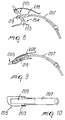
- Figures 8 to 10 show an embodiment, in which the lever is constituted by a plate which can be rigidly coupled to a first flap of the shoe and from which two wings 203 protrude laterally; a first end 204 of a U-shaped lever arm 205 is pivoted to the wings, and at least one transverse pivot 219 is arranged between the wings; a rack 209 is detachably associable with the transverse pivot and is connected to an elongated member such as a band 207 which is in turn connected to a second shoe flap to be joined.
- a rack 209 is detachably associable with the transverse pivot and is connected to an elongated member such as a band 207 which is in turn connected to a second shoe flap to be joined.
- Figures 11 to 13 show another embodiment, in which the lever is constituted by a plate which can be rigidly coupled to a first flap of the shoe and from which two wings 303 protrude laterally.
- a first end 304 of a U-shaped lever arm 305 is pivoted to the wings, and a member 306 for connection to a metal cable or string 307 is rotatably associated with the lever arm.
- the cable or string is connected to a tooth 308 which selectively interacts at a rack 309 which is associated with a second shoe flap to be joined.
- An auxiliary grip lever 311 for the user is rotatably associated at the lever arm 305 proximate to the second free end 310.
- the lever 311 is rotatably pivoted, at one end, at a pivot 312 which is arranged at right angles to the wings of the lever arm 305.
- Rotary connection occurs in contrast with a flexible member, such as a torsion spring 313 which is coaxial to the pivot and is locked, at its ends, to the lever arm and to the auxiliary lever; the spring allows to keep the auxiliary lever, as shown in Figure 13, arranged axially with respect to the lever arm 305.
- the auxiliary lever is allowed to turn for example clockwise through approximately 180 ⁇ , so that it can be used in the rotation that can be imparted to the lever arm 305.
- the lateral opening of the auxiliary lever facilitates closure and opening, while the inactive position of the auxiliary lever also acts as a member for preventing the opening of the lever arm 305.
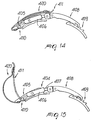
- Figures 14 and 15 show another embodiment, in which the lever is constituted by a plate which can be rigidly coupled to a first flap of the shoe and from which two wings protrude laterally.
- a first end 404 of a U-shaped lever arm 405 is pivoted to the wings, and a member 406 for connection to a metal cable or string 407 is rotatably associated with the lever arm; in turn, the cable or string is connected to a tooth 408 which selectively interacts at a rack 409 which is associated with a second shoe flap to be joined.
- An auxiliary grip lever 411 for the user is rotatably associated at the lever arm 405, proximate to the second free end 410.
- a soft grip member 420 such as a band which is associated, at its other end, for example with the free end of the lever 411, is associated with the auxiliary lever in a lower region, at the second end 410.
- the band is approximately as wide as the auxiliary lever and has a such a length that it is tensioned when the auxiliary lever is arranged adjacent to the lever arm, the band causes no hindrance during sports practice; on the contrary, it is suitable to further facilitate the user's grip as soon as the auxiliary lever is raised, since a loop is formed.
Landscapes
- Footwear And Its Accessory, Manufacturing Method And Apparatuses (AREA)
Claims (14)
- Hebelverschluss (1) für Sportschuhe, umfassend: einen Hebelarm (5, 105, 305, 405); der an einem ersten Ende drehbar verbunden ist mit einer Halterung, die starr an einer Klappe eines Schuhs angekoppelt ist, und einen Hilfsgriffhebel (11, 111, 311, 411), dadurch gekennzeichnet, dass der Hilfsgriffhebel mit dem Hebelarm verbunden ist und mindestens zwei Positionen relativ zu dem Hebelarm (5, 105, 305, 405) ausbildet, eine Ruheposition und eine Betriebsposition, und in der Betriebsposition der Hilfsgriffhebel (11, 111, 311, 411 ) die Arbeitslänge des Hebelarmes (5, 105, 305, 405) vergrößert.
- Hebelverschluss nach Anspruch 1, umfassend eine Platte (2), welche starr an eine erste Klappe des Schuhs gekoppelt werden kann und von der zwei Schenkel oder Endabschnitte (3) seitlich abstehen, wobei ein erstes Ende (4) des Hebelarmes (5) an den Endabschnitten schwenkbar gelagert ist, ein Verbindungsteil (6) zum Verbinden mit einem länglichen Teil (7), das drehbar mit dem Hebelarm verbunden ist, wobei das längliche Teil (7) wiederum mit einer Klinke (8) verbunden ist, die selektiv in ein Hakenteil (9) eingreift, welches mit einer zweiten zu verbindenden Klappe des Schuhs verbunden ist, dadurch gekennzeichnet, dass der Hilfsgriffhebel (11) für den Benutzer mit dem Hebelarm proximal zu einem zweiten freien Ende des Hebelarmes verbunden ist.
- Hebelverschluss nach Anspruch 2, dadurch gekennzeichnet, dass zum Verbinden der Endabschnitte des Hebelarmes (5) der Hilfsgriffhebel (11) an einem Ende drehbar gelagert ist an einer Schwenkachse (12), wobei die Schwenkverbindung entgegen der Kraft von mindestens einem flexiblen Teil, wie zum Beispiel einer Feder (13), auftritt.
- Hebelverschluss nach Anspruch 3, dadurch gekennzeichnet, dass die Feder (13) im Wesentlichen U-förmig ist, wobei sie eine Basis (14) hat, welche an der oberen Seitenfläche (15) des Hilfshebels (11) eine Wechselwirkung ausübt, und Schenkel oder Endabschnitte hat, welche koaxial um die Schwenkachse (12) gewunden sind, um an ihren freien Enden mit einer oberen Seitenfläche (16) des Hebelarmes (5) zusammenzuwirken, wobei die Form des Hilfshebels und die Anordnung der Feder so ist, dass der Hilfshebel gezwungen ist, sich selbst zum Hebelarm angrenzend anzuordnen, wobei sein freies Ende zur Klinke gerichtet ist.
- Hebelverschluss nach Anspruch 4, dadurch gekennzeichnet, dass das freie Ende (17) des Hilfshebels (11) eine bogenähnliche Form hat, derart, dass es von der Oberfläche der Klinke (8) absteht, um ein gutes Greifen für den Benutzer zu ermöglichen.
- Hebelverschluss nach Anspruch 5, dadurch gekennzeichnet, dass es dem Hilfshebel (11) ermöglicht wird, durch Spannen der Feder (13) im Gegenuhrzeigersinn so zu drehen, dass er mit dem zweiten freien Ende (10) des Hebelarmes (5) durch Anstoßen zusammenwirkt, wobei eine von dem Benutzer durchgeführte zusätzliche Rotation des Hilfshebels (11) eine Rotation des Hebelarmes erzeugt, so dass die Klappen befestigt werden.
- Hebelverschluss nach einem oder mehreren der vorhergehenden Ansprüche, dadurch gekennzeichnet, dass mindestens ein Sitz an dem zweiten freien Ende des Hebelarmes vorgesehen ist, wobei der mindestens eine Sitz ein Durchgangssitz ist und mit einer gegebenen Neigung bezüglich der oberen Seitenfläche des Hebelarmes versehen ist.
- Hebelverschluss nach Anspruch 7, dadurch gekennzeichnet, dass das Ende des Hilfshebels innerhalb des Sitzes angeordnet sein kann, wobei der separate Hilfshebel geeignet geformt ist, um von dem Hebelarm so abzustehen, dass dessen Arbeitslänge zeitweise vergrößert wird.
- Hebelverschluss nach Anspruch 8, dadurch gekennzeichnet, dass der Hilfshebel ein freies Ende hat, welches breiter ist als das Ende, welches an dem Sitz so angeordnet sein kann, dass der Griff für den Benutzer zusätzlich vergrößert wird.
- Hebelverschluss nach einem oder mehreren der vorhergehenden Ansprüche, dadurch gekennzeichnet, dass er umfasst eine Platte, die starr mit einer ersten Klappe des Schuhs starr gekoppelt sein kann und von welcher zwei Endabschnitte (303) seitlich abstehen, ein erstes Ende (304) eines U-förmigen Hebelarmes (305), das an den Endabschnitten schwenkbar gelagert ist, wobei mindestens eine zwischen den Endabschnitten des Armes quer verlaufende Schwenkachse angeordnet ist, ein Hakenteil (309), das demontierbar verbunden ist mit der quer verlaufenden Schwenkachse ist, wobei das Hakenteil mit einem langgestreckten Teil (307) verbunden ist, welches wiederum mit einer zweiten zu verbindenden Schuhklappe verbunden ist.
- Hebelverschluss nach einem oder mehreren der vorgehenden Ansprüche, dadurch gekennzeichnet, dass ein Benutzer-Hilfsgriffhebel (311) mit dem Hebelarm (305) verbunden ist, proximal zu dem zweiten freien Ende (310) und an einem Ende an einer Schwenkachse (312) drehbar gelagert ist, die rechtwinklig zu den Endabschnitten des Hebelarmes (305) angeordnet ist, wobei die Drehverbindung entgegen einem flexiblen Teil, wie zum Beispiel einer Torsionsfeder (313), auftritt, die koaxial zu der Schwenkachse ist und an ihren Enden mit dem Hebelarm (305) und dem Hilfshebel festgestellt ist, wobei die Feder geeignet ist, den Hilfshebel in axiale Anordnung zum Hebelarm (305) zu zwingen.
- Hebelverschluss nach Anspruch 11, dadurch gekennzeichnet, dass es dem Hilfshebel (311) ermöglicht ist, um etwa 180° zu drehen, um zu ermöglichen, ihn bei der nachfolgenden Rotation zu verwenden, welche auf den Hebelarm (305) ausgeübt werden kann, wobei die Seitenöffnung des Hilfshebels das Schließen und Öffnen des Hebelarmes erleichtert, während die inaktive Position des Hilfsarmes zusätzlich als ein Teil zum Verhindern des Öffnens des Hebelarmes wirkt.
- Hebelverschluss nach einem oder mehreren der vorhergehenden Ansprüche, dadurch gekennzeichnet, dass ein Ende eines Weichgriffelementes (420), zum Beispiel eines Bandes, mit dem freien Ende des Hilfshebels (411) verbunden ist, mit seinem anderen Ende mit dem Hilfshebel in einer tieferen Region des zweiten Endes (410) verbunden ist.
- Hebelverschluss nach Anspruch 13, dadurch gekennzeichnet, dass das Band ungefähr so breit ist wie der Hilfshebel und eine solche Länge hat, dass es gespannt ist, wenn der Hilfshebel an den Hebelarm angrenzt, wobei das Band (420) eine Griffschleife für den Benutzer bildet; wenn der Hilfshebel angehoben wird.
Applications Claiming Priority (2)
| Application Number | Priority Date | Filing Date | Title |
|---|---|---|---|
| IT98MI000646A IT1298824B1 (it) | 1998-03-27 | 1998-03-27 | Struttura di leva,particolarmente per calzature sportive |
| ITMI980646 | 1998-03-27 |
Publications (2)
| Publication Number | Publication Date |
|---|---|
| EP0945080A1 EP0945080A1 (de) | 1999-09-29 |
| EP0945080B1 true EP0945080B1 (de) | 2003-11-19 |
Family
ID=11379533
Family Applications (1)
| Application Number | Title | Priority Date | Filing Date |
|---|---|---|---|
| EP99105741A Expired - Lifetime EP0945080B1 (de) | 1998-03-27 | 1999-03-22 | Hebelverschluss für Sportschuhe |
Country Status (5)
| Country | Link |
|---|---|
| US (1) | US6145168A (de) |
| EP (1) | EP0945080B1 (de) |
| AT (1) | ATE254411T1 (de) |
| DE (1) | DE69912872T2 (de) |
| IT (1) | IT1298824B1 (de) |
Families Citing this family (16)
| Publication number | Priority date | Publication date | Assignee | Title |
|---|---|---|---|---|
| US6712405B2 (en) * | 2000-11-07 | 2004-03-30 | Bombardier Recreational Products Inc. | Latch mechanism for a snowmobile engine cover |
| US6872358B2 (en) | 2002-01-16 | 2005-03-29 | Lifescan, Inc. | Test strip dispenser |
| FR2883138B1 (fr) * | 2005-03-15 | 2007-08-03 | Salomon Sa | Crochet sur-dimensionne |
| FR2887410B1 (fr) * | 2005-06-28 | 2007-09-21 | Salomon Sa | Dispositif de fermeture pour chaussure de ski |
| FR2912295B1 (fr) | 2007-02-13 | 2010-01-01 | Salomon Sa | Crochet pour la fermeture d'une chaussure de sport |
| IT1392425B1 (it) * | 2008-12-23 | 2012-03-02 | Baggio | Dispositivo di chiusura, particolarmente per calzature sportive. |
| EP2415364B1 (de) * | 2010-08-02 | 2013-06-05 | Rossignol Lange S.R.L. | Hebel mit Verlängerung zum Zumachen eines Sportschuhs |
| ITTV20130005A1 (it) * | 2013-01-17 | 2014-07-18 | Amteknostampi Spa | Struttura di dispositivo di apertura e particolarmente leve per calzature sportive |
| DE102014108222B4 (de) | 2014-06-12 | 2017-02-16 | TRüTZSCHLER GMBH & CO. KG | Wickelmaschine zur Erzeugung von Wattewickel und Verfahren zum Wickeln von Faserbändern |
| DE102015105670A1 (de) | 2015-04-14 | 2016-10-20 | TRüTZSCHLER GMBH & CO. KG | Wickelmaschine zur Erzeugung von Wattewickeln und Verfahren zum Wickeln einer Watte |
| US10369037B2 (en) * | 2015-04-17 | 2019-08-06 | Vision Quest Industries Incorporated | Orthotic device with snap fit cuff and latch mechanism |
| ITUB20154702A1 (it) * | 2015-10-15 | 2017-04-15 | Tecnica Group Spa | Piastra di ancoraggio per dispositivo di chiusura per una calzatura sportiva |
| ITUA20164063A1 (it) * | 2016-06-01 | 2017-12-01 | Tecnica Group Spa | Dispositivo di chiusura per una calzatura sportiva |
| EP3262967B1 (de) * | 2016-06-27 | 2019-04-17 | Rossignol Lange S.R.L. | Verschlussschnalle für skischuh |
| IT201700009944A1 (it) * | 2017-01-30 | 2018-07-30 | Tecnica Group Spa | Dispositivo di chiusura per calzatura sportiva provvisto di una leva di azionamento migliorata |
| US12279676B2 (en) * | 2022-10-27 | 2025-04-22 | Radford Colberg LLC | Buckle apparatus |
Family Cites Families (14)
| Publication number | Priority date | Publication date | Assignee | Title |
|---|---|---|---|---|
| US2704071A (en) * | 1953-11-23 | 1955-03-15 | Becker Paul | Skin retractor |
| CH424536A (de) * | 1962-12-13 | 1966-11-15 | Rieker & Co | Spannhebelverschluss für Skischuhe |
| US3662435A (en) * | 1970-08-06 | 1972-05-16 | Allsop I J | Ratcheting buckle for ski boots and the like |
| DE2700795A1 (de) * | 1977-01-11 | 1978-07-13 | Dieter Harms | Schnallenschliesser und -oeffner fuer skischuhe |
| DE2912946A1 (de) * | 1979-03-31 | 1980-10-09 | Koehler | Geraet zur erleichterung des verschliessens von schnallen an ski-schuhen |
| US4424636A (en) * | 1982-06-22 | 1984-01-10 | Lange International S.A. | Buckle fastener, notably for sports footwear |
| DE3576462D1 (de) * | 1984-02-10 | 1990-04-19 | Tmc Corp | Fersenhalter. |
| IT8422395U1 (it) * | 1984-06-25 | 1985-12-25 | Olivieri Icaro & C | Gruppo di tensionamento per l'allacciatura di una calzatura sportiva, particolarmente di uno scarpone da sci. |
| US4587870A (en) * | 1984-11-08 | 1986-05-13 | Kenneth Colburn | Ski boot buckle tool |
| CH672400A5 (de) * | 1987-07-21 | 1989-11-30 | Lange Int Sa | |
| ITTV940037U1 (it) * | 1994-07-13 | 1996-01-13 | Nordica Spa | Struttura di leva, particolarmente per calzature sportive |
| FR2733396B1 (fr) * | 1995-04-27 | 1997-07-04 | Salomon Sa | Levier de serrage avec crochet reglable |
| IT1279339B1 (it) * | 1995-07-31 | 1997-12-09 | Nordica Spa | Dispositivo di serraggio per calzature sportive |
| IT242084Y1 (it) * | 1996-02-05 | 2001-06-04 | Nordica Spa | Dispositivo di serraggio per calzature sportive |
-
1998
- 1998-03-27 IT IT98MI000646A patent/IT1298824B1/it active IP Right Grant
-
1999
- 1999-03-22 AT AT99105741T patent/ATE254411T1/de not_active IP Right Cessation
- 1999-03-22 EP EP99105741A patent/EP0945080B1/de not_active Expired - Lifetime
- 1999-03-22 DE DE69912872T patent/DE69912872T2/de not_active Expired - Lifetime
- 1999-03-22 US US09/273,992 patent/US6145168A/en not_active Expired - Lifetime
Also Published As
| Publication number | Publication date |
|---|---|
| EP0945080A1 (de) | 1999-09-29 |
| DE69912872T2 (de) | 2004-11-11 |
| IT1298824B1 (it) | 2000-02-02 |
| ATE254411T1 (de) | 2003-12-15 |
| DE69912872D1 (de) | 2003-12-24 |
| ITMI980646A1 (it) | 1999-09-27 |
| US6145168A (en) | 2000-11-14 |
Similar Documents
| Publication | Publication Date | Title |
|---|---|---|
| EP0945080A1 (de) | Hebelverschluss für Sportschuhe | |
| US6955362B2 (en) | Binding for coupling a shoe to a snowboard and the like | |
| US6050005A (en) | Snowboard boot binding mechanism | |
| EP0252516A2 (de) | Klemverschluss für Schuhe und Stiefel | |
| EP0809950A2 (de) | Einrichtung zum Spannen und Justieren der Zahnleiste von einer Verschlussvorrichtung für Sportschuhwerk | |
| JPS59137001A (ja) | 運動用履物,特にスキ−靴 | |
| JPH04212305A (ja) | リヤ・エントリー型アルペンスキー靴 | |
| JPS6230761B2 (de) | ||
| JPH07204008A (ja) | 締め金具 | |
| EP0342463B1 (de) | Skistiefel mit verbessertem Sitz | |
| US4757621A (en) | Ski boot | |
| EP4727400A1 (de) | Befestigungsanordnung für sportschuhe | |
| EP0363778A2 (de) | Automatisch lösbare Fusshaltevorrichtung, insbesondere für Schischuhe mit Hintereinstieg | |
| EP0645102B1 (de) | Verschlussvorrichtung, insbesondere für Sportschuhe | |
| US7603795B2 (en) | Buckle for a sports boot and a sports boot having such buckle | |
| EP0284978B1 (de) | Schliess- und Haltevorrichtung, insbesondere für Schischuhe | |
| JPH0637682Y2 (ja) | スキー靴の締付装置 | |
| EP0434902A1 (de) | Einstellbare Verschlusseinrichtung speziell für Skistiefel | |
| EP0157118A1 (de) | Fussanpassungsvorrichtung, insbesondere für Skischuhe mit hinterem Einstieg | |
| US5191728A (en) | Ski boot having a rear spoiler, a front cuff and a linkage, wherein the linkage extends from lateral spaced locations at the sides of the boot to anchorage points | |
| US5079859A (en) | Rear-entry ski boot | |
| CA2321742A1 (en) | Dual-action buckle | |
| EP0916279B1 (de) | Schliessvorrichtung, insbesondere für Skischuhe | |
| EP0410080A2 (de) | Fuss-Sicherheitseinrichtung insbesondere für Schistiefel | |
| EP0904811B1 (de) | Vorrichtung zum Verbinden eines Schuhes an Sportgeräte |
Legal Events
| Date | Code | Title | Description |
|---|---|---|---|
| PUAI | Public reference made under article 153(3) epc to a published international application that has entered the european phase |
Free format text: ORIGINAL CODE: 0009012 |
|
| AK | Designated contracting states |
Kind code of ref document: A1 Designated state(s): AT CH DE ES FR IT LI |
|
| AX | Request for extension of the european patent |
Free format text: AL;LT;LV;MK;RO;SI |
|
| 17P | Request for examination filed |
Effective date: 19991118 |
|
| AKX | Designation fees paid |
Free format text: AT CH DE ES FR IT LI |
|
| 17Q | First examination report despatched |
Effective date: 20020129 |
|
| RAP1 | Party data changed (applicant data changed or rights of an application transferred) |
Owner name: HTM SPORT S.P.A. |
|
| GRAH | Despatch of communication of intention to grant a patent |
Free format text: ORIGINAL CODE: EPIDOS IGRA |
|
| GRAS | Grant fee paid |
Free format text: ORIGINAL CODE: EPIDOSNIGR3 |
|
| GRAA | (expected) grant |
Free format text: ORIGINAL CODE: 0009210 |
|
| AK | Designated contracting states |
Kind code of ref document: B1 Designated state(s): AT CH DE ES FR IT LI |
|
| REG | Reference to a national code |
Ref country code: CH Ref legal event code: EP |
|
| RAP2 | Party data changed (patent owner data changed or rights of a patent transferred) |
Owner name: HEAD TECHNOLOGY GMBH |
|
| REF | Corresponds to: |
Ref document number: 69912872 Country of ref document: DE Date of ref document: 20031224 Kind code of ref document: P |
|
| PG25 | Lapsed in a contracting state [announced via postgrant information from national office to epo] |
Ref country code: ES Free format text: LAPSE BECAUSE OF FAILURE TO SUBMIT A TRANSLATION OF THE DESCRIPTION OR TO PAY THE FEE WITHIN THE PRESCRIBED TIME-LIMIT Effective date: 20040302 |
|
| REG | Reference to a national code |
Ref country code: CH Ref legal event code: NV Representative=s name: KEMENY AG PATENTANWALTBUERO |
|
| ET | Fr: translation filed | ||
| PLBE | No opposition filed within time limit |
Free format text: ORIGINAL CODE: 0009261 |
|
| STAA | Information on the status of an ep patent application or granted ep patent |
Free format text: STATUS: NO OPPOSITION FILED WITHIN TIME LIMIT |
|
| 26N | No opposition filed |
Effective date: 20040820 |
|
| PGFP | Annual fee paid to national office [announced via postgrant information from national office to epo] |
Ref country code: AT Payment date: 20090323 Year of fee payment: 11 |
|
| PGFP | Annual fee paid to national office [announced via postgrant information from national office to epo] |
Ref country code: CH Payment date: 20090327 Year of fee payment: 11 |
|
| REG | Reference to a national code |
Ref country code: CH Ref legal event code: PL |
|
| PG25 | Lapsed in a contracting state [announced via postgrant information from national office to epo] |
Ref country code: AT Free format text: LAPSE BECAUSE OF NON-PAYMENT OF DUE FEES Effective date: 20100322 |
|
| PG25 | Lapsed in a contracting state [announced via postgrant information from national office to epo] |
Ref country code: LI Free format text: LAPSE BECAUSE OF NON-PAYMENT OF DUE FEES Effective date: 20100331 Ref country code: CH Free format text: LAPSE BECAUSE OF NON-PAYMENT OF DUE FEES Effective date: 20100331 |
|
| PGFP | Annual fee paid to national office [announced via postgrant information from national office to epo] |
Ref country code: IT Payment date: 20140326 Year of fee payment: 16 |
|
| PGFP | Annual fee paid to national office [announced via postgrant information from national office to epo] |
Ref country code: DE Payment date: 20140520 Year of fee payment: 16 |
|
| REG | Reference to a national code |
Ref country code: DE Ref legal event code: R119 Ref document number: 69912872 Country of ref document: DE |
|
| PG25 | Lapsed in a contracting state [announced via postgrant information from national office to epo] |
Ref country code: IT Free format text: LAPSE BECAUSE OF NON-PAYMENT OF DUE FEES Effective date: 20150322 |
|
| PG25 | Lapsed in a contracting state [announced via postgrant information from national office to epo] |
Ref country code: DE Free format text: LAPSE BECAUSE OF NON-PAYMENT OF DUE FEES Effective date: 20151001 |
|
| REG | Reference to a national code |
Ref country code: FR Ref legal event code: PLFP Year of fee payment: 18 |
|
| REG | Reference to a national code |
Ref country code: FR Ref legal event code: PLFP Year of fee payment: 19 |
|
| REG | Reference to a national code |
Ref country code: FR Ref legal event code: PLFP Year of fee payment: 20 |
|
| PGFP | Annual fee paid to national office [announced via postgrant information from national office to epo] |
Ref country code: FR Payment date: 20180220 Year of fee payment: 20 |