EP0945104A1 - Systéme et procédé destinés à la visualisation de l'activité d'un organe - Google Patents
Systéme et procédé destinés à la visualisation de l'activité d'un organe Download PDFInfo
- Publication number
- EP0945104A1 EP0945104A1 EP98810261A EP98810261A EP0945104A1 EP 0945104 A1 EP0945104 A1 EP 0945104A1 EP 98810261 A EP98810261 A EP 98810261A EP 98810261 A EP98810261 A EP 98810261A EP 0945104 A1 EP0945104 A1 EP 0945104A1
- Authority
- EP
- European Patent Office
- Prior art keywords
- organ
- signals
- activity
- catheter
- pictorial representation
- Prior art date
- Legal status (The legal status is an assumption and is not a legal conclusion. Google has not performed a legal analysis and makes no representation as to the accuracy of the status listed.)
- Withdrawn
Links
- 230000000694 effects Effects 0.000 title claims abstract description 76
- 210000000056 organ Anatomy 0.000 title claims abstract description 70
- 238000000034 method Methods 0.000 title claims description 16
- 238000003384 imaging method Methods 0.000 claims abstract description 12
- 238000002604 ultrasonography Methods 0.000 claims description 38
- 238000001514 detection method Methods 0.000 claims description 12
- 238000012800 visualization Methods 0.000 claims description 12
- 230000000007 visual effect Effects 0.000 claims description 11
- 238000005259 measurement Methods 0.000 claims description 4
- 238000002679 ablation Methods 0.000 claims description 2
- 238000011282 treatment Methods 0.000 description 4
- 206010003119 arrhythmia Diseases 0.000 description 3
- 238000000576 coating method Methods 0.000 description 3
- 238000013461 design Methods 0.000 description 3
- 230000004807 localization Effects 0.000 description 3
- 238000011298 ablation treatment Methods 0.000 description 2
- 239000011248 coating agent Substances 0.000 description 2
- 238000003745 diagnosis Methods 0.000 description 2
- 230000002123 temporal effect Effects 0.000 description 2
- 238000012285 ultrasound imaging Methods 0.000 description 2
- 210000001015 abdomen Anatomy 0.000 description 1
- 230000015572 biosynthetic process Effects 0.000 description 1
- 230000000747 cardiac effect Effects 0.000 description 1
- 238000013153 catheter ablation Methods 0.000 description 1
- 239000003086 colorant Substances 0.000 description 1
- 230000001419 dependent effect Effects 0.000 description 1
- 230000005672 electromagnetic field Effects 0.000 description 1
- 210000003238 esophagus Anatomy 0.000 description 1
- 238000011156 evaluation Methods 0.000 description 1
- 239000011521 glass Substances 0.000 description 1
- 230000003902 lesion Effects 0.000 description 1
- 238000013507 mapping Methods 0.000 description 1
- 239000000463 material Substances 0.000 description 1
- 239000000126 substance Substances 0.000 description 1
- 238000007794 visualization technique Methods 0.000 description 1
Images

Classifications
-
- A—HUMAN NECESSITIES
- A61—MEDICAL OR VETERINARY SCIENCE; HYGIENE
- A61B—DIAGNOSIS; SURGERY; IDENTIFICATION
- A61B8/00—Diagnosis using ultrasonic, sonic or infrasonic waves
- A61B8/12—Diagnosis using ultrasonic, sonic or infrasonic waves in body cavities or body tracts, e.g. by using catheters
Definitions
- an assignment unit assigns the second signals each as location information local area of the organ for whose activity the each second signal is representative.
- the visual in a visualization unit Representation, the second signals as well as each associated location information combined into an image, that both the visual representation and the Activity of the organ in each other Way includes.
- activities of an organ becomes a visual by means of ultrasonic measurement signals Representation of the organ or parts of the organ, especially a three-dimensional visual representation, generated.
- second signals in particular electrical signals which are representative of the Activity of the organ are, with the said pictorial Representation to an image of the organ or parts of the Organ combined, the image being both the pictorial Representation as well as the activity of the organ in each other includes locally assigned manner.
- Fig. 1 shows the symbolic representation essential components of an embodiment of the system according to the invention, the whole with the Reference numeral 1 is designated.
- the inventive System 1 for the visualization of activities of an organ 10 comprises an imaging ultrasound device 2 for Providing first signals, a Reconstruction unit 7, which consists of the first signals a pictorial representation of the organ 10 or parts of the organ 10 created, a measuring device 3 for locally resolved detection of second signals, which are representative of the activity of the organ 10, as well an assignment unit 6, which the second signals the local area of the Organ 10 assigns, for whose activity the respective second signal is representative.
- System 1 includes also a visualization unit 8, which from the pictorial representation, the second signals and the each associated location information a picture of the organ 10 or generated from parts of the organ 10, the image both the visual representation and the activity of the organ 10 in a mutually localized manner includes.
- the imaging ultrasound device 2 comprises one Measuring head 22 for emitting ultrasonic signals and for Receive the body structure to be imaged reflected echo signals.
- the measuring head 22 is one Ultrasound module 21 controlled.
- the measuring head 22 transmits the received echo signals to the Ultrasound module 21, which these echo signals preprocessed, e.g. B. amplifies and / or filters, and them then as the first signals to the Reconstruction unit 7 forwards.
- the Reconstruction unit 7 converts the first signals by means of procedures known per se for two or three-dimensional imaging into a format which a pictorial representation of the organ 10 enables.
- the ultrasound device 2 and the Reconstruction unit 7 designed such that it a three-dimensional (3D) pictorial representation of the Allow organ 10 or parts of the organ.
- Three-dimensional representation means that the representation is actually three-dimensional or, that it is flat but a three-dimensional one Gives an impression, e.g. B. using methods of spatial or perspective representation or the Projection.
- the assignment unit 6 can also in the Ultrasound device 2 can be integrated. Can also the reconstruction unit 7 and / or the Ultrasound module 21 and / or the visualization unit 8 and / or the assignment unit 6 is a structural unit form, which is part of the ultrasonic device 2.
- the electrodes 41a, 41c can be used as contact electrodes or for contactless Detection of the activity signals can be configured.
- the Electrodes 41a, 41c are via connection lines 42a, 42c connected to the control and measuring unit 5, to send the activity signals they have captured to the Control and evaluation unit 5 to be transmitted.
- the Acquisition of the activity signals by means of the electrodes 41a, 41c can be both unipolar and bipolar.
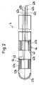
- the catheter 4 preferably also comprises at least one Ultrasonic transducer 44 for receiving and / or transmitting of ultrasonic signals because it makes it simple and Safe localization of the catheter 4 or the electrodes 41a, 41c in the heart 10 by means of ultrasound becomes. This localization will be discussed later described in detail.
- Each ultrasonic transducer 44 comprises a transducer layer 43 made of piezoelectric Material between the two electrodes 41a and 41b is embedded.
- the one shown in Fig. 2 Embodiment are the ultrasonic transducers 44 each designed in a ring and arranged so that the Include catheter 4 along its circumference.
- the electrodes 41a and 41b are shown exaggeratedly thick in FIG.
- the electrodes 41a and 41b are conductive Coatings on the surfaces of the converter layers 43.
- those of the Converter layer 43 generated electrical signals tapped and via the connecting lines 42a, 42b Control and measuring unit 5 are supplied.
- the converter layers 43 can be electrical impulses from the control and Measuring unit 5 via the connecting lines 42a, 42b and the electrodes 41a, 41b on the converter layers 43 are transmitted, for sending ultrasonic signals be stimulated.
- the electrodes 41a have a double function. she serve on the one hand for the local recording of the Activity signals from the heart 10 and form to the other part of the ultrasonic transducer 44.
- the measure, that the ultrasonic transducer 44 also as an electrode for serves local detection of electrical activity advantageous because it is a particularly space-saving and allows inexpensive design of the catheter 4.
- Ultrasonic transducer 44 Except for the annular configuration of the Ultrasonic transducer 44 is of course also z. Legs plate-shaped design possible, that is Ultrasonic transducer 44 does not encompass the entire scope the catheter 4. Furthermore, it is possible on a Catheter 4 both plate-shaped and ring-shaped Provide ultrasonic transducer 44. Of course he can Ultrasonic transducers 44 also have other shapes and / or be arranged inside the catheter.
- the ultrasonic transducer 44 and the Electrodes 41a which serve to detect the activity, can also be structurally separate from one another.
- the catheter 4 as shown in FIG. 2, for this purpose comprises a plurality of electrodes 41a, 41c, so that multiple activity signals from different local Areas of the heart 10 can be detected simultaneously.
- the Electrodes 41a, 41c can be one-dimensional, i.e. along a line, but especially also two-dimensional, d. H. on an area, or three-dimensional, for example on one Catheter, the distal end of which can be spatially stretched is arranged.
- ultrasonic transducers 44 are provided to determine the location of the catheter in space, and so that the position of the individual electrodes 41a, 41c, easier and more precise to be able to determine.
- an ultrasonic transducer 44 so that it is in relation to the catheter 4th is mobile. This makes it possible to Ultrasonic transducers 44 in different positions to move with respect to the catheter 4, thus each to determine the spatial position of the individual electrodes.
- the measuring head 22 To operate the system, first the measuring head 22 the ultrasonic device 2 near the body structure to be imaged, here of the heart 10, placed.
- the measuring head 22 is preferably used for this purpose in the Introduced esophagus because from there a achieve particularly good visual representation of the heart leaves.
- Ultrasonic echo signals are generated by ultrasonic module 21 in connection with the reconstruction unit 7 a preferably three-dimensional pictorial representation of the Heart.
- this pictorial representation approximately in real time, whereby continuously a current visualization of the heart is made possible.
- the catheter 4 is in a known manner in the Heart 10 introduced. Depending on how many electrodes 41a, 41c the catheter 4 for detecting the electrical Has activity signals, it is either on navigated different places in the heart 10 to get there successively the local activity, e.g. Belly contactless, to capture, or it will be at the same time several positions of the heart 10 the local Activities recorded.
- the activity signals are over the connecting lines 42a, 42b to the drive and Measurement unit 5 forwarded.
- the catheter 4 is preferably located in the Hearts 10 but using ultrasound.
- the Catheter 4 - as already mentioned - at least one Ultrasonic transducer 44.
- the catheter 4 is preferably located in the Hearts 10 but using ultrasound.
- the Catheter 4 - as already mentioned - at least one Ultrasonic transducer 44.
- the catheter 4 at least one Ultrasonic transducer 44.
- these apply Explanations in a similar manner also for a plurality of ultrasonic transducers 44 on the catheter 4.
- the ultrasound transducer 44 can either be for the passive or be designed for active operation. “Passive” means that the ultrasonic transducer 44 only for the Reception of ultrasound signals is used "active” means that he himself send out ultrasonic signals can.
- the measuring head 22 sends the ultrasound device 2 Ultrasonic signals, which among other things also Ultrasound transducer 44 of the catheter can hit.
- Ultrasonic transducer 44 sends this when hit by an ultrasonic wave appropriate information to the Allocation unit 6 or the ultrasound module 21.
- Da it is known at what times and in which Direction from the measuring head 22 ultrasonic waves or - impulses were sent out, how big the Ultrasound propagation speed is and when receive an ultrasonic echo signal from the measuring head 22 the time of the encounter may be one Ultrasonic wave on the ultrasonic transducer 44 in Catheter 4 a spatial position of the ultrasound transducer 44 and thus the electrodes 41a, 41c.
- the location information can also the activity signal assigned, that is, the local area of the heart 10, for the activity of which the signal is representative.
- the ultrasonic transducer 44 If the ultrasonic transducer 44 is operated actively, then it converts a received ultrasound pulse from the Measuring head 22 comes into an electrical signal and transmits this to a transponder that for example in the control and measuring unit 5 can be integrated or as a separate structural Unit is realized. The transponder then generates an Send signal and send this to the ultrasonic transducer 44, which then emits an ultrasound signal. This Ultrasonic signal is received by the measuring head 22 and on the ultrasound module 21 is forwarded. That from Ultrasonic transducer 44 emitted ultrasonic signal preferably has a special characteristic, such as for example a modulation, a special duration or Intensity to make it particularly easy from the Echo signals from the body structure to be imaged originate, is distinguishable. Thus, the Ultrasonic device 2, the spatial location of the Ultrasonic transducer 44 and thus the location of the Detect electrodes 41a, 41c. That way too can each activity signal its specific Location information can be assigned.
- the ultrasonic transducer 44 can thus both passive as well as in active mode an automatic Determination of the position of the catheter 4 in the heart 10 respectively. Because the allocation unit 6 can if necessary in connection with the Ultrasound device 2, using the signals from the ultrasound transducer (s) 44, everyone second signal, here every local activity signal, automatically assign the associated location information, the indicates for which local area of the heart 10 the respective activity signal is representative.
- each activity signal has assigned its location information
- the Activity signals along with their location information the visualization unit 8 transmits. This creates then from the geometric form, that is, from the Reconstruction unit 7 provided data for the pictorial representation, and from the activity signals with assigned location information an image of the heart 10, where the picture is both the pictorial representation as well the activity signals in each other locally assigned Way includes. This means that the electrical Activities of the heart of the three-dimensional pictorial Representation to be overlaid. In a preferred one The location of the Catheters 4 in the heart 10 included in the picture.
- the image can be displayed in different ways respectively.
- the time spread of the EKG in numbers or symbols on the respective associated location. It is also possible the temporally and spatially resolved EKG using Represent false colors by any delay time relative to a predeterminable starting time certain color is assigned. It is also possible the spread of activity as moving To represent wavefront.
- the image with the preferably three-dimensional Representation and the activity signals can be done with the help various visualization media such as one Monitor, a so-called head mounted display (HMD), or a screen - possibly in connection with a pair of 3D glasses.
- HMD head mounted display
- the preferably three-dimensional pictorial representation only be created once, and the current second Signals are always new with this visual Representation combined or incorporated into this. Also it is possible to visualize it on request or renew at definable discrete time intervals. There is also the possibility, especially with such fast ultrasound systems 2, as already in the European Patent Application No. 97811021.1 cited are disclosed, which are preferably three-dimensional pictorial representation approximately in real time, ie continuously, update. Furthermore it is possible, only parts of the image continuously or at discrete time intervals To update. For example, such parts of the pictorial representation, the areas are updated of the heart reflect that of particular interest are, e.g. B. the area in which the Catheter.
- the system according to the invention is preferably for transesophageal cardiac imaging and intracardiac ECG measurement is designed, so are quite other embodiments possible.
- the Acquisition of ultrasound signals for the visual Representation also take place from outside the body, that is, without inserting the measuring head 22 into the body.
- the measuring device 3 can also be designed in this way be that the second signals (activity signals) can grasp from outside the body, for example in the form of a surface ECG.
- the Measuring device 3 then comprises, for example, at least an electrode for local detection of the electrical Activity of the heart or organ 10, this being Electrode is attached to the body surface.
- the system or method according to the invention can be used advantageously for ablation treatments.
- Energy form for denaturing the tissue is common High frequency energy used.
- the system or method according to the invention is not based on limited examination or treatment of the heart. It is also suitable for other organs and / or others second signals, for example the determination of others Parameters related to the function of the organ related, e.g. B. pressure, temperature or chemical Parameters.
Landscapes
- Life Sciences & Earth Sciences (AREA)
- Health & Medical Sciences (AREA)
- Medical Informatics (AREA)
- Molecular Biology (AREA)
- Nuclear Medicine, Radiotherapy & Molecular Imaging (AREA)
- Pathology (AREA)
- Radiology & Medical Imaging (AREA)
- Engineering & Computer Science (AREA)
- Biomedical Technology (AREA)
- Heart & Thoracic Surgery (AREA)
- Physics & Mathematics (AREA)
- Biophysics (AREA)
- Surgery (AREA)
- Animal Behavior & Ethology (AREA)
- General Health & Medical Sciences (AREA)
- Public Health (AREA)
- Veterinary Medicine (AREA)
- Ultra Sonic Daignosis Equipment (AREA)
- Measurement And Recording Of Electrical Phenomena And Electrical Characteristics Of The Living Body (AREA)
- Measurement Of Length, Angles, Or The Like Using Electric Or Magnetic Means (AREA)
- Closed-Circuit Television Systems (AREA)
- Surgical Instruments (AREA)
Priority Applications (2)
| Application Number | Priority Date | Filing Date | Title |
|---|---|---|---|
| EP98810261A EP0945104A1 (fr) | 1998-03-25 | 1998-03-25 | Systéme et procédé destinés à la visualisation de l'activité d'un organe |
| JP11036916A JP2000000242A (ja) | 1998-03-25 | 1999-02-16 | 臓器活動の視覚的表示のためのシステム及び方法 |
Applications Claiming Priority (1)
| Application Number | Priority Date | Filing Date | Title |
|---|---|---|---|
| EP98810261A EP0945104A1 (fr) | 1998-03-25 | 1998-03-25 | Systéme et procédé destinés à la visualisation de l'activité d'un organe |
Publications (1)
| Publication Number | Publication Date |
|---|---|
| EP0945104A1 true EP0945104A1 (fr) | 1999-09-29 |
Family
ID=8236012
Family Applications (1)
| Application Number | Title | Priority Date | Filing Date |
|---|---|---|---|
| EP98810261A Withdrawn EP0945104A1 (fr) | 1998-03-25 | 1998-03-25 | Systéme et procédé destinés à la visualisation de l'activité d'un organe |
Country Status (2)
| Country | Link |
|---|---|
| EP (1) | EP0945104A1 (fr) |
| JP (1) | JP2000000242A (fr) |
Cited By (4)
| Publication number | Priority date | Publication date | Assignee | Title |
|---|---|---|---|---|
| US6716166B2 (en) | 2000-08-18 | 2004-04-06 | Biosense, Inc. | Three-dimensional reconstruction using ultrasound |
| US6773402B2 (en) | 2001-07-10 | 2004-08-10 | Biosense, Inc. | Location sensing with real-time ultrasound imaging |
| WO2005027766A1 (fr) * | 2003-09-01 | 2005-03-31 | Siemens Aktiengesellschaft | Procede et dispositif d'assistance visuelle a l'utilisation electrophysiologique d'un catheter dans le coeur |
| WO2005027765A1 (fr) * | 2003-09-01 | 2005-03-31 | Siemens Aktiengesellschaft | Procede et dispositif pour assister visuellement la mise en place d'un catheter electrophysiologique dans le coeur |
Families Citing this family (14)
| Publication number | Priority date | Publication date | Assignee | Title |
|---|---|---|---|---|
| US6556695B1 (en) * | 1999-02-05 | 2003-04-29 | Mayo Foundation For Medical Education And Research | Method for producing high resolution real-time images, of structure and function during medical procedures |
| US20070106147A1 (en) * | 2005-11-01 | 2007-05-10 | Altmann Andres C | Controlling direction of ultrasound imaging catheter |
| US8945117B2 (en) | 2009-02-11 | 2015-02-03 | Boston Scientific Scimed, Inc. | Insulated ablation catheter devices and methods of use |
| WO2011008444A1 (fr) | 2009-06-30 | 2011-01-20 | Boston Scientific Scimed, Inc. | Cathéter hybride irrigué ouvert de cartographie et d'ablation |
| US9089340B2 (en) | 2010-12-30 | 2015-07-28 | Boston Scientific Scimed, Inc. | Ultrasound guided tissue ablation |
| US9241687B2 (en) | 2011-06-01 | 2016-01-26 | Boston Scientific Scimed Inc. | Ablation probe with ultrasonic imaging capabilities |
| EP2755587B1 (fr) | 2011-09-14 | 2018-11-21 | Boston Scientific Scimed, Inc. | Dispositif d'ablation ayant de multiples modes d'ablation |
| AU2012308464B2 (en) | 2011-09-14 | 2016-10-20 | Boston Scientific Scimed, Inc. | Ablation device with ionically conductive balloon |
| WO2013102072A1 (fr) | 2011-12-28 | 2013-07-04 | Boston Scientific Scimed, Inc. | Sonde d'ablation ayant une capacité d'imagerie ultrasonore |
| CA2860636A1 (fr) | 2012-01-10 | 2013-07-18 | Boston Scientific Scimed, Inc. | Systeme d'electrophysiologie |
| US8945015B2 (en) | 2012-01-31 | 2015-02-03 | Koninklijke Philips N.V. | Ablation probe with fluid-based acoustic coupling for ultrasonic tissue imaging and treatment |
| WO2016061002A1 (fr) | 2014-10-13 | 2016-04-21 | Boston Scientific Scimed Inc. | Diagnostic et traitement de tissus à l'aide de mini-électrodes |
| EP4316361A3 (fr) | 2014-10-24 | 2024-05-01 | Boston Scientific Scimed Inc. | Dispositifs médicaux dotés d'un ensemble d'électrode souple couplé à une pointe d'ablation |
| US9743854B2 (en) | 2014-12-18 | 2017-08-29 | Boston Scientific Scimed, Inc. | Real-time morphology analysis for lesion assessment |
Citations (5)
| Publication number | Priority date | Publication date | Assignee | Title |
|---|---|---|---|---|
| US4821731A (en) * | 1986-04-25 | 1989-04-18 | Intra-Sonix, Inc. | Acoustic image system and method |
| US4936281A (en) * | 1989-04-13 | 1990-06-26 | Everest Medical Corporation | Ultrasonically enhanced RF ablation catheter |
| EP0381816A2 (fr) * | 1989-02-06 | 1990-08-16 | Arzco Medical Electronics, Inc. | Electrode multiple en forme de feuille adhésive |
| WO1990013259A1 (fr) * | 1989-05-03 | 1990-11-15 | Tomtec Tomographic Technologies Gmbh | Dispositif d'echocardiographie trans×sophagienne |
| US5159931A (en) * | 1988-11-25 | 1992-11-03 | Riccardo Pini | Apparatus for obtaining a three-dimensional reconstruction of anatomic structures through the acquisition of echographic images |
-
1998
- 1998-03-25 EP EP98810261A patent/EP0945104A1/fr not_active Withdrawn
-
1999
- 1999-02-16 JP JP11036916A patent/JP2000000242A/ja active Pending
Patent Citations (5)
| Publication number | Priority date | Publication date | Assignee | Title |
|---|---|---|---|---|
| US4821731A (en) * | 1986-04-25 | 1989-04-18 | Intra-Sonix, Inc. | Acoustic image system and method |
| US5159931A (en) * | 1988-11-25 | 1992-11-03 | Riccardo Pini | Apparatus for obtaining a three-dimensional reconstruction of anatomic structures through the acquisition of echographic images |
| EP0381816A2 (fr) * | 1989-02-06 | 1990-08-16 | Arzco Medical Electronics, Inc. | Electrode multiple en forme de feuille adhésive |
| US4936281A (en) * | 1989-04-13 | 1990-06-26 | Everest Medical Corporation | Ultrasonically enhanced RF ablation catheter |
| WO1990013259A1 (fr) * | 1989-05-03 | 1990-11-15 | Tomtec Tomographic Technologies Gmbh | Dispositif d'echocardiographie trans×sophagienne |
Cited By (8)
| Publication number | Priority date | Publication date | Assignee | Title |
|---|---|---|---|---|
| US6716166B2 (en) | 2000-08-18 | 2004-04-06 | Biosense, Inc. | Three-dimensional reconstruction using ultrasound |
| US6773402B2 (en) | 2001-07-10 | 2004-08-10 | Biosense, Inc. | Location sensing with real-time ultrasound imaging |
| WO2005027766A1 (fr) * | 2003-09-01 | 2005-03-31 | Siemens Aktiengesellschaft | Procede et dispositif d'assistance visuelle a l'utilisation electrophysiologique d'un catheter dans le coeur |
| WO2005027765A1 (fr) * | 2003-09-01 | 2005-03-31 | Siemens Aktiengesellschaft | Procede et dispositif pour assister visuellement la mise en place d'un catheter electrophysiologique dans le coeur |
| CN1874735B (zh) * | 2003-09-01 | 2010-05-26 | 西门子公司 | 对电生理导管的心脏应用提供可视化支持的方法和装置 |
| AU2004273587B2 (en) * | 2003-09-01 | 2011-03-10 | Biosense Webster, Inc. | Method and device for visually supporting an electrophysiology catheter application in the heart |
| US9078567B2 (en) | 2003-09-01 | 2015-07-14 | Siemens Aktiengesellschaft | Method and device for visually supporting an electrophysiology catheter application in the heart |
| US9668704B2 (en) | 2003-09-01 | 2017-06-06 | Biosense Webster (Israel) Ltd. | Method and device for visually assisting an electrophysiological use of a catheter in the heart |
Also Published As
| Publication number | Publication date |
|---|---|
| JP2000000242A (ja) | 2000-01-07 |
Similar Documents
| Publication | Publication Date | Title |
|---|---|---|
| DE10355275B4 (de) | Kathedereinrichtung | |
| EP0945104A1 (fr) | Systéme et procédé destinés à la visualisation de l'activité d'un organe | |
| DE69728142T2 (de) | Katheter mit anpassbarer form | |
| DE69434296T2 (de) | Vorrichtung und verfahren zur behandlung von arrythmien des herzens | |
| DE69728446T2 (de) | Anordnung zur führung von behandlungsinstrumenten in zonen des körperinneren | |
| DE69514238T2 (de) | Medizinisches diagnose-, behandlungs- und darstellungssystem | |
| DE60207127T2 (de) | Vorrichtung zum Messen einer Mehrzahl von elektrischen Signalen vom Körper eines Patienten | |
| DE60118463T2 (de) | Multi Elektrodenkatheter, System, und Anwendungsmethode | |
| DE60115996T2 (de) | System und Methode zum Erkennen von Kontakt zwischen Gewebe und Elektrode | |
| DE60219905T2 (de) | System und verfahren zum feststellen der loslösung einer implantiebaren medizinischen vorrichtung | |
| DE10340546B4 (de) | Verfahren und Vorrichtung zur visuellen Unterstützung einer elektrophysiologischen Katheteranwendung im Herzen | |
| DE69434065T2 (de) | Elektrophysiologische signal-abnahme zur flächenhaften darstellung, zur stimulation und zur ablation | |
| DE69937887T2 (de) | System zur dynamischen korrektur eines dreidimensionalen graphischen modells einer körperregion | |
| DE69533124T2 (de) | Vorrichtung zur Analyse und Überwachung von Infarkten und der Ischämie des Myokards | |
| DE10340544B4 (de) | Vorrichtung zur visuellen Unterstützung einer elektrophysiologischen Katheteranwendung im Herzen | |
| DE60120245T2 (de) | Katheter zur Erzeugung einer elektrischen Darstellung einer Herzkammer | |
| DE69716306T2 (de) | Anordnungen zur darstellung von körperinneren gewebeteilen | |
| EP0652726B1 (fr) | Procede de visualisation de l'interieur de corps | |
| EP2124802B1 (fr) | Procédé et système d'assistance visuelle pour l'application d'un cathéter | |
| EP1245191A2 (fr) | Méthode et système d'imagerie à ultrason pour la détermination de la position d'un catheter | |
| DE102007043731A1 (de) | Medizinische Bildaufnahmeeinrichtung, insbesondere zur Erstellung von Bildaufnahmen im Rahmen einer Behandlung von Herzrhythmusstörungen, sowie zugehöriges Verfahren | |
| DE19844152A1 (de) | System und Verfahren zum Lokalisieren eines Katheters | |
| DE102006043200A1 (de) | Automatisiertes Bildgebungs- und Therapiesystem | |
| DE102008002850A1 (de) | Verfahren zur Anwendung eines Bildgebungs- und Navigationssystems | |
| DE102017010318B3 (de) | Ösophaguselektrodensonde und Vorrichtung zur kardiologischen Behandlung und/oder Diagnose |
Legal Events
| Date | Code | Title | Description |
|---|---|---|---|
| PUAI | Public reference made under article 153(3) epc to a published international application that has entered the european phase |
Free format text: ORIGINAL CODE: 0009012 |
|
| AK | Designated contracting states |
Kind code of ref document: A1 Designated state(s): DE ES FR GB IT NL |
|
| AX | Request for extension of the european patent |
Free format text: AL;LT;LV;MK;RO;SI |
|
| 17P | Request for examination filed |
Effective date: 20000308 |
|
| AKX | Designation fees paid |
Free format text: DE ES FR GB IT NL |
|
| STAA | Information on the status of an ep patent application or granted ep patent |
Free format text: STATUS: THE APPLICATION IS DEEMED TO BE WITHDRAWN |
|
| 18D | Application deemed to be withdrawn |
Effective date: 20011002 |