EP0945161A1 - Verfahren zur Trennung von Stickstoff aus der Luft - Google Patents
Verfahren zur Trennung von Stickstoff aus der Luft Download PDFInfo
- Publication number
- EP0945161A1 EP0945161A1 EP99301989A EP99301989A EP0945161A1 EP 0945161 A1 EP0945161 A1 EP 0945161A1 EP 99301989 A EP99301989 A EP 99301989A EP 99301989 A EP99301989 A EP 99301989A EP 0945161 A1 EP0945161 A1 EP 0945161A1
- Authority
- EP
- European Patent Office
- Prior art keywords
- stream
- air
- beds
- waste
- purification unit
- Prior art date
- Legal status (The legal status is an assumption and is not a legal conclusion. Google has not performed a legal analysis and makes no representation as to the accuracy of the status listed.)
- Withdrawn
Links
- IJGRMHOSHXDMSA-UHFFFAOYSA-N Atomic nitrogen Chemical compound N#N IJGRMHOSHXDMSA-UHFFFAOYSA-N 0.000 title claims abstract description 50
- 229910052757 nitrogen Inorganic materials 0.000 title claims abstract description 25
- 239000003463 adsorbent Substances 0.000 claims abstract description 44
- 238000000746 purification Methods 0.000 claims abstract description 30
- 238000001179 sorption measurement Methods 0.000 claims abstract description 25
- 239000002699 waste material Substances 0.000 claims abstract description 24
- QVGXLLKOCUKJST-UHFFFAOYSA-N atomic oxygen Chemical compound [O] QVGXLLKOCUKJST-UHFFFAOYSA-N 0.000 claims abstract description 21
- 239000001301 oxygen Substances 0.000 claims abstract description 21
- 229910052760 oxygen Inorganic materials 0.000 claims abstract description 21
- 239000007788 liquid Substances 0.000 claims abstract description 17
- 238000000034 method Methods 0.000 claims abstract description 16
- 239000012535 impurity Substances 0.000 claims description 19
- CURLTUGMZLYLDI-UHFFFAOYSA-N Carbon dioxide Chemical compound O=C=O CURLTUGMZLYLDI-UHFFFAOYSA-N 0.000 claims description 16
- 239000007789 gas Substances 0.000 claims description 15
- 229910002092 carbon dioxide Inorganic materials 0.000 claims description 8
- 239000001569 carbon dioxide Substances 0.000 claims description 8
- 238000004821 distillation Methods 0.000 claims description 6
- 230000008929 regeneration Effects 0.000 claims description 6
- 238000011069 regeneration method Methods 0.000 claims description 6
- 238000005057 refrigeration Methods 0.000 claims description 5
- 238000010926 purge Methods 0.000 claims description 4
- 230000006835 compression Effects 0.000 claims description 3
- 238000007906 compression Methods 0.000 claims description 3
- 238000000926 separation method Methods 0.000 description 5
- XLYOFNOQVPJJNP-UHFFFAOYSA-N water Substances O XLYOFNOQVPJJNP-UHFFFAOYSA-N 0.000 description 5
- 239000002912 waste gas Substances 0.000 description 4
- 239000002826 coolant Substances 0.000 description 2
- 238000004519 manufacturing process Methods 0.000 description 2
- 238000010992 reflux Methods 0.000 description 2
- UGFAIRIUMAVXCW-UHFFFAOYSA-N Carbon monoxide Chemical compound [O+]#[C-] UGFAIRIUMAVXCW-UHFFFAOYSA-N 0.000 description 1
- PNEYBMLMFCGWSK-UHFFFAOYSA-N aluminium oxide Inorganic materials [O-2].[O-2].[O-2].[Al+3].[Al+3] PNEYBMLMFCGWSK-UHFFFAOYSA-N 0.000 description 1
- 229910002091 carbon monoxide Inorganic materials 0.000 description 1
- 230000003247 decreasing effect Effects 0.000 description 1
- 238000010586 diagram Methods 0.000 description 1
- 238000007599 discharging Methods 0.000 description 1
- 229930195733 hydrocarbon Natural products 0.000 description 1
- 150000002430 hydrocarbons Chemical class 0.000 description 1
- VUZPPFZMUPKLLV-UHFFFAOYSA-N methane;hydrate Chemical compound C.O VUZPPFZMUPKLLV-UHFFFAOYSA-N 0.000 description 1
- 238000011144 upstream manufacturing Methods 0.000 description 1
- 238000013022 venting Methods 0.000 description 1
Images

Classifications
-
- F—MECHANICAL ENGINEERING; LIGHTING; HEATING; WEAPONS; BLASTING
- F25—REFRIGERATION OR COOLING; COMBINED HEATING AND REFRIGERATION SYSTEMS; HEAT PUMP SYSTEMS; MANUFACTURE OR STORAGE OF ICE; LIQUEFACTION SOLIDIFICATION OF GASES
- F25J—LIQUEFACTION, SOLIDIFICATION OR SEPARATION OF GASES OR GASEOUS OR LIQUEFIED GASEOUS MIXTURES BY PRESSURE AND COLD TREATMENT OR BY BRINGING THEM INTO THE SUPERCRITICAL STATE
- F25J3/00—Processes or apparatus for separating the constituents of gaseous or liquefied gaseous mixtures involving the use of liquefaction or solidification
- F25J3/02—Processes or apparatus for separating the constituents of gaseous or liquefied gaseous mixtures involving the use of liquefaction or solidification by rectification, i.e. by continuous interchange of heat and material between a vapour stream and a liquid stream
- F25J3/04—Processes or apparatus for separating the constituents of gaseous or liquefied gaseous mixtures involving the use of liquefaction or solidification by rectification, i.e. by continuous interchange of heat and material between a vapour stream and a liquid stream for air
- F25J3/04248—Generation of cold for compensating heat leaks or liquid production, e.g. by Joule-Thompson expansion
- F25J3/04254—Generation of cold for compensating heat leaks or liquid production, e.g. by Joule-Thompson expansion using the cold stored in external cryogenic fluids
-
- B—PERFORMING OPERATIONS; TRANSPORTING
- B01—PHYSICAL OR CHEMICAL PROCESSES OR APPARATUS IN GENERAL
- B01D—SEPARATION
- B01D53/00—Separation of gases or vapours; Recovering vapours of volatile solvents from gases; Chemical or biological purification of waste gases, e.g. engine exhaust gases, smoke, fumes, flue gases, aerosols
- B01D53/02—Separation of gases or vapours; Recovering vapours of volatile solvents from gases; Chemical or biological purification of waste gases, e.g. engine exhaust gases, smoke, fumes, flue gases, aerosols by adsorption, e.g. preparative gas chromatography
- B01D53/04—Separation of gases or vapours; Recovering vapours of volatile solvents from gases; Chemical or biological purification of waste gases, e.g. engine exhaust gases, smoke, fumes, flue gases, aerosols by adsorption, e.g. preparative gas chromatography with stationary adsorbents
- B01D53/047—Pressure swing adsorption
-
- F—MECHANICAL ENGINEERING; LIGHTING; HEATING; WEAPONS; BLASTING
- F25—REFRIGERATION OR COOLING; COMBINED HEATING AND REFRIGERATION SYSTEMS; HEAT PUMP SYSTEMS; MANUFACTURE OR STORAGE OF ICE; LIQUEFACTION SOLIDIFICATION OF GASES
- F25J—LIQUEFACTION, SOLIDIFICATION OR SEPARATION OF GASES OR GASEOUS OR LIQUEFIED GASEOUS MIXTURES BY PRESSURE AND COLD TREATMENT OR BY BRINGING THEM INTO THE SUPERCRITICAL STATE
- F25J3/00—Processes or apparatus for separating the constituents of gaseous or liquefied gaseous mixtures involving the use of liquefaction or solidification
- F25J3/02—Processes or apparatus for separating the constituents of gaseous or liquefied gaseous mixtures involving the use of liquefaction or solidification by rectification, i.e. by continuous interchange of heat and material between a vapour stream and a liquid stream
- F25J3/04—Processes or apparatus for separating the constituents of gaseous or liquefied gaseous mixtures involving the use of liquefaction or solidification by rectification, i.e. by continuous interchange of heat and material between a vapour stream and a liquid stream for air
- F25J3/04151—Purification and (pre-)cooling of the feed air; recuperative heat-exchange with product streams
- F25J3/04163—Hot end purification of the feed air
- F25J3/04169—Hot end purification of the feed air by adsorption of the impurities
- F25J3/04181—Regenerating the adsorbents
-
- F—MECHANICAL ENGINEERING; LIGHTING; HEATING; WEAPONS; BLASTING
- F25—REFRIGERATION OR COOLING; COMBINED HEATING AND REFRIGERATION SYSTEMS; HEAT PUMP SYSTEMS; MANUFACTURE OR STORAGE OF ICE; LIQUEFACTION SOLIDIFICATION OF GASES
- F25J—LIQUEFACTION, SOLIDIFICATION OR SEPARATION OF GASES OR GASEOUS OR LIQUEFIED GASEOUS MIXTURES BY PRESSURE AND COLD TREATMENT OR BY BRINGING THEM INTO THE SUPERCRITICAL STATE
- F25J3/00—Processes or apparatus for separating the constituents of gaseous or liquefied gaseous mixtures involving the use of liquefaction or solidification
- F25J3/02—Processes or apparatus for separating the constituents of gaseous or liquefied gaseous mixtures involving the use of liquefaction or solidification by rectification, i.e. by continuous interchange of heat and material between a vapour stream and a liquid stream
- F25J3/04—Processes or apparatus for separating the constituents of gaseous or liquefied gaseous mixtures involving the use of liquefaction or solidification by rectification, i.e. by continuous interchange of heat and material between a vapour stream and a liquid stream for air
- F25J3/044—Processes or apparatus for separating the constituents of gaseous or liquefied gaseous mixtures involving the use of liquefaction or solidification by rectification, i.e. by continuous interchange of heat and material between a vapour stream and a liquid stream for air using a single pressure main column system only
-
- B—PERFORMING OPERATIONS; TRANSPORTING
- B01—PHYSICAL OR CHEMICAL PROCESSES OR APPARATUS IN GENERAL
- B01D—SEPARATION
- B01D2253/00—Adsorbents used in seperation treatment of gases and vapours
- B01D2253/10—Inorganic adsorbents
- B01D2253/104—Alumina
-
- B—PERFORMING OPERATIONS; TRANSPORTING
- B01—PHYSICAL OR CHEMICAL PROCESSES OR APPARATUS IN GENERAL
- B01D—SEPARATION
- B01D2257/00—Components to be removed
- B01D2257/50—Carbon oxides
- B01D2257/504—Carbon dioxide
-
- B—PERFORMING OPERATIONS; TRANSPORTING
- B01—PHYSICAL OR CHEMICAL PROCESSES OR APPARATUS IN GENERAL
- B01D—SEPARATION
- B01D2257/00—Components to be removed
- B01D2257/80—Water
-
- B—PERFORMING OPERATIONS; TRANSPORTING
- B01—PHYSICAL OR CHEMICAL PROCESSES OR APPARATUS IN GENERAL
- B01D—SEPARATION
- B01D2259/00—Type of treatment
- B01D2259/40—Further details for adsorption processes and devices
- B01D2259/40001—Methods relating to additional, e.g. intermediate, treatment of process gas
-
- B—PERFORMING OPERATIONS; TRANSPORTING
- B01—PHYSICAL OR CHEMICAL PROCESSES OR APPARATUS IN GENERAL
- B01D—SEPARATION
- B01D2259/00—Type of treatment
- B01D2259/40—Further details for adsorption processes and devices
- B01D2259/402—Further details for adsorption processes and devices using two beds
-
- B—PERFORMING OPERATIONS; TRANSPORTING
- B01—PHYSICAL OR CHEMICAL PROCESSES OR APPARATUS IN GENERAL
- B01D—SEPARATION
- B01D53/00—Separation of gases or vapours; Recovering vapours of volatile solvents from gases; Chemical or biological purification of waste gases, e.g. engine exhaust gases, smoke, fumes, flue gases, aerosols
- B01D53/02—Separation of gases or vapours; Recovering vapours of volatile solvents from gases; Chemical or biological purification of waste gases, e.g. engine exhaust gases, smoke, fumes, flue gases, aerosols by adsorption, e.g. preparative gas chromatography
- B01D53/04—Separation of gases or vapours; Recovering vapours of volatile solvents from gases; Chemical or biological purification of waste gases, e.g. engine exhaust gases, smoke, fumes, flue gases, aerosols by adsorption, e.g. preparative gas chromatography with stationary adsorbents
- B01D53/047—Pressure swing adsorption
- B01D53/053—Pressure swing adsorption with storage or buffer vessel
-
- B—PERFORMING OPERATIONS; TRANSPORTING
- B01—PHYSICAL OR CHEMICAL PROCESSES OR APPARATUS IN GENERAL
- B01D—SEPARATION
- B01D53/00—Separation of gases or vapours; Recovering vapours of volatile solvents from gases; Chemical or biological purification of waste gases, e.g. engine exhaust gases, smoke, fumes, flue gases, aerosols
- B01D53/26—Drying gases or vapours
- B01D53/261—Drying gases or vapours by adsorption
-
- F—MECHANICAL ENGINEERING; LIGHTING; HEATING; WEAPONS; BLASTING
- F25—REFRIGERATION OR COOLING; COMBINED HEATING AND REFRIGERATION SYSTEMS; HEAT PUMP SYSTEMS; MANUFACTURE OR STORAGE OF ICE; LIQUEFACTION SOLIDIFICATION OF GASES
- F25J—LIQUEFACTION, SOLIDIFICATION OR SEPARATION OF GASES OR GASEOUS OR LIQUEFIED GASEOUS MIXTURES BY PRESSURE AND COLD TREATMENT OR BY BRINGING THEM INTO THE SUPERCRITICAL STATE
- F25J2200/00—Processes or apparatus using separation by rectification
- F25J2200/72—Refluxing the column with at least a part of the totally condensed overhead gas
-
- F—MECHANICAL ENGINEERING; LIGHTING; HEATING; WEAPONS; BLASTING
- F25—REFRIGERATION OR COOLING; COMBINED HEATING AND REFRIGERATION SYSTEMS; HEAT PUMP SYSTEMS; MANUFACTURE OR STORAGE OF ICE; LIQUEFACTION SOLIDIFICATION OF GASES
- F25J—LIQUEFACTION, SOLIDIFICATION OR SEPARATION OF GASES OR GASEOUS OR LIQUEFIED GASEOUS MIXTURES BY PRESSURE AND COLD TREATMENT OR BY BRINGING THEM INTO THE SUPERCRITICAL STATE
- F25J2205/00—Processes or apparatus using other separation and/or other processing means
- F25J2205/60—Processes or apparatus using other separation and/or other processing means using adsorption on solid adsorbents, e.g. by temperature-swing adsorption [TSA] at the hot or cold end
- F25J2205/64—Processes or apparatus using other separation and/or other processing means using adsorption on solid adsorbents, e.g. by temperature-swing adsorption [TSA] at the hot or cold end by pressure-swing adsorption [PSA] at the hot end
-
- F—MECHANICAL ENGINEERING; LIGHTING; HEATING; WEAPONS; BLASTING
- F25—REFRIGERATION OR COOLING; COMBINED HEATING AND REFRIGERATION SYSTEMS; HEAT PUMP SYSTEMS; MANUFACTURE OR STORAGE OF ICE; LIQUEFACTION SOLIDIFICATION OF GASES
- F25J—LIQUEFACTION, SOLIDIFICATION OR SEPARATION OF GASES OR GASEOUS OR LIQUEFIED GASEOUS MIXTURES BY PRESSURE AND COLD TREATMENT OR BY BRINGING THEM INTO THE SUPERCRITICAL STATE
- F25J2205/00—Processes or apparatus using other separation and/or other processing means
- F25J2205/60—Processes or apparatus using other separation and/or other processing means using adsorption on solid adsorbents, e.g. by temperature-swing adsorption [TSA] at the hot or cold end
- F25J2205/66—Regenerating the adsorption vessel, e.g. kind of reactivation gas
- F25J2205/72—Pressurising or depressurising the adsorption vessel
-
- F—MECHANICAL ENGINEERING; LIGHTING; HEATING; WEAPONS; BLASTING
- F25—REFRIGERATION OR COOLING; COMBINED HEATING AND REFRIGERATION SYSTEMS; HEAT PUMP SYSTEMS; MANUFACTURE OR STORAGE OF ICE; LIQUEFACTION SOLIDIFICATION OF GASES
- F25J—LIQUEFACTION, SOLIDIFICATION OR SEPARATION OF GASES OR GASEOUS OR LIQUEFIED GASEOUS MIXTURES BY PRESSURE AND COLD TREATMENT OR BY BRINGING THEM INTO THE SUPERCRITICAL STATE
- F25J2210/00—Processes characterised by the type or other details of the feed stream
- F25J2210/42—Nitrogen
-
- F—MECHANICAL ENGINEERING; LIGHTING; HEATING; WEAPONS; BLASTING
- F25—REFRIGERATION OR COOLING; COMBINED HEATING AND REFRIGERATION SYSTEMS; HEAT PUMP SYSTEMS; MANUFACTURE OR STORAGE OF ICE; LIQUEFACTION SOLIDIFICATION OF GASES
- F25J—LIQUEFACTION, SOLIDIFICATION OR SEPARATION OF GASES OR GASEOUS OR LIQUEFIED GASEOUS MIXTURES BY PRESSURE AND COLD TREATMENT OR BY BRINGING THEM INTO THE SUPERCRITICAL STATE
- F25J2290/00—Other details not covered by groups F25J2200/00 - F25J2280/00
- F25J2290/62—Details of storing a fluid in a tank
-
- Y—GENERAL TAGGING OF NEW TECHNOLOGICAL DEVELOPMENTS; GENERAL TAGGING OF CROSS-SECTIONAL TECHNOLOGIES SPANNING OVER SEVERAL SECTIONS OF THE IPC; TECHNICAL SUBJECTS COVERED BY FORMER USPC CROSS-REFERENCE ART COLLECTIONS [XRACs] AND DIGESTS
- Y02—TECHNOLOGIES OR APPLICATIONS FOR MITIGATION OR ADAPTATION AGAINST CLIMATE CHANGE
- Y02C—CAPTURE, STORAGE, SEQUESTRATION OR DISPOSAL OF GREENHOUSE GASES [GHG]
- Y02C20/00—Capture or disposal of greenhouse gases
- Y02C20/40—Capture or disposal of greenhouse gases of CO2
-
- Y—GENERAL TAGGING OF NEW TECHNOLOGICAL DEVELOPMENTS; GENERAL TAGGING OF CROSS-SECTIONAL TECHNOLOGIES SPANNING OVER SEVERAL SECTIONS OF THE IPC; TECHNICAL SUBJECTS COVERED BY FORMER USPC CROSS-REFERENCE ART COLLECTIONS [XRACs] AND DIGESTS
- Y10—TECHNICAL SUBJECTS COVERED BY FORMER USPC
- Y10S—TECHNICAL SUBJECTS COVERED BY FORMER USPC CROSS-REFERENCE ART COLLECTIONS [XRACs] AND DIGESTS
- Y10S62/00—Refrigeration
- Y10S62/912—External refrigeration system
- Y10S62/913—Liquified gas
Definitions
- the present invention relates to a method of and a plant for separating nitrogen from air.
- compressed and purified air is distilled or rectified in a single rectification column and an extemal source of liquid nitrogen (or liquid air) is used to provide refrigeration for the plant.
- liquid nitrogen or liquid air
- Such a plant is sometimes referred to in the art as a "liquid assist plant”.
- the purification of the air is performed so as to remove carbon dioxide and moisture. If high purity products are required, it is sometimes desirable to remove other impurities such as carbon monoxide and hydrocarbons upstream of the rectification column.
- Modern air separation plants use pre-purification units employing adsorbent beds to adsorb particularly water vapour and carbon dioxide from the incoming air.
- the adsorbent beds are utilised in continuous cycles in which one adsorbent bed functions on-line to adsorb the impurities from the air with one or more other off-line adsorbent beds are being regenerated.
- One known cycle is referred to in the art as a pressure swing adsorption cycle because the beds adsorb at an operating pressure, typically set by the main air compressor, and are regenerated at a lower pressure at which the adsorbed impurities are desorbed and are discharged from the pre-purification unit.
- the regeneration in a pressure swing adsorption cycle is effected by first venting an adsorbent bed to atmosphere so that the adsorbed impurities desorb from the bed and flow towards the feed end of the bed. Thereafter, the adsorbent bed is purged with a stream of nitrogen further to desorb the impurities and to discharge them from the bed. The adsorbent bed is repressurised with part of the compressed air. This use of the compressed air to be rectified not only represents an increase in the required capacity of the compressor but also an additional energy expenditure beyond that required for the distillation itself.
- the present invention provides a method of and plant for separating nitrogen from air in which a liquid- assist plant is operated with a pressure swing adsorption, pre-purification unit in a more energy efficient manner and such that the capacity of the compressor relative to the rate of production of nitrogen product from the plant is able to be decreased.
- the invention provides a method of separating a nitrogen product and an oxygen-enriched "waste" gas from compressed, purified air in a liquid assist plant wherein purification of the air is performed by pressure swing adsorption and the pressure swing adsorption cycle includes a step of repressurising a bed from which the impurities have been desorbed, characterised in that part of the repressurisation is performed with a stream of the oxygen-enriched "waste" gas.
- the invention also provides a liquid assist plant for separating a nitrogen product and an oxygen-enriched "waste” gas from air including a pressure swing adsorption purification unit, wherein the said unit includes a repressurisation pipeline, characterised in that the repressurisation pipeline is able in operation to be opened to a flow of the oxygen-enriched "waste” gas.
- the air is compressed to form an air stream.
- the air stream is purified by removing impurities that comprise carbon dioxide and moisture from the air stream this produces a compressed and purified air stream.
- the compressed and purified air stream is introduced into a distillation column configured to separate the air to produce the nitrogen and a waste stream enriched in oxygen. Refrigeration is introduced from an external source of liquid (e.g. liquid nitrogen).
- the air stream is purified in pre-purification unit having at least two adsorbent beds containing an adsorbent to adsorb the impurities.
- the pre-purification unit is operated by subjecting each of the adsorbent beds to the steps of adsorption to adsorb the impurities from the air stream, thereby to produce a pre-purification unit product stream, and regeneration to regenerate the adsorbent and to repressurise each of the adsorbent beds to an operational pressure of the pre-purification unit.
- the compressed and purified air stream is formed from at least of the pre-purification unit product stream and each of the adsorbent beds is in part repressurised with the waste stream.
- the partial repressurisation (or backfill) step with the waste stream is an effective way to save power in a liquid assist plant having a pre-purification unit operating in accordance with pressure swing adsorption cycle.
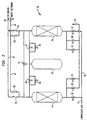
- air is filtered in a filter 10 and compressed in a compressor 12 to produce a compressed air stream 14.
- Heat of compression is removed in an after-cooler 16 and the air is purified in a pre-purification unit 18 effective to remove impurities, particularly carbon dioxide and moisture (water vapour) therefrom.
- the resultant compressed and purified air stream 20 is cooled in a main heat exchanger 22 to a temperature suitable for its rectification.
- the resulting cooled air stream is introduced into a distillation (i.e. rectification) column 24 that is designed to produce a nitrogen-rich overhead fraction (typically at least 99.9% pure) in an overhead or top region 26 of the column 24 and a bottom oxygen-rich fraction in a bottom region 28 of the column 24.
- a distillation (i.e. rectification) column 24 that is designed to produce a nitrogen-rich overhead fraction (typically at least 99.9% pure) in an overhead or top region 26 of the column 24 and a bottom oxygen-rich fraction in a bottom region 28 of the column 24.
- a part of the nitrogen-rich overhead fraction is condensed within a head condenser 30.
- the resultant condensate is employed as reflux in the distillation column 24.
- a liquid nitrogen stream "LN 2 " is introduced from an external source into the top region 26 of the column 24. This liquid nitrogen stream enhances the reflux in the column 24.
- the coolant for the head condenser 30 is formed by removing a stream 32 from the bottom region 28 of the column 24 and expanding it through an expansion valve 33.
- the coolant stream 32 vaporises in the head condenser to produce a "waste" oxygen-enriched gaseous stream 34 which is passed through the main heat exchanger 22 counter-currently to the air to be separated.
- the waste stream 34 is thus warmed typically to approximately ambient temperature and, as will be described below, is utilised within the pre-purification unit 18.
- a gaseous nitrogen product stream 36 is taken from the top region 26 of the column 24 and is fully warned (to approximately ambient temperature) within the main heat exchanger to produce a gaseous nitrogen product stream which is labelled "PGN" in Figure 1.
- the pre-purification unit 18 includes an inlet manifold 38 through which the compressed air stream enters.
- the purified air is discharged from a product manifold 40.
- the waste oxygen-enriched stream 34 is admitted to the pre-purification unit 18 through a waste stream manifold 42.
- just two adsorbent beds 44 and 46 are provided, there being sufficient adsorbent for the size of the air separation plant.
- the adsorbent may, for example, consist of activated alumina.
- a pressure vessel 48 that does not contain any adsorbent is also provided.
- the pre-purification unit 18 operates in a continuous ten step cycle as illustrated in the chart below.
- Step No. Adsorbent Bed 44
- Adsorbent Bed 46 Pressure Vessel 48 Duration (seconds) 1 Pressurise Adsorption Hold 300
- Adsorption Depressurise Pressurise 50 3
- Adsorption Regeneration Pressurise 355 4
- Adsorption Back-fill Pressurise 30 5
- Adsorption Pressurise Hold 300 Depressurise Adsorption Pressurise 50
- Regeneration Adsorption Pressurise 355 Back-fill Adsorption Pressurise 30
- Pressurise/Equalise Adsorption Equalise 30 10
- Pressurise/Equalise Adsorption Equalise 30 10
- step 1 the valves 52 and 54 are in an open position.
- the compressed air is thus admitted to the bed 46.
- Impurities, particularly water vapour and carbon dioxide, are adsorbed within the adsorbent bed 46.
- Most of the thus purified air is discharged via a check-valve (one-way valve) 61 to the product manifold 40, but a small part of the purified air flows through the valve 54 and pressurises the bed 44.
- the pressure vessel 48 is isolated from the beds 44 and 46.
- Check-valves 56 and 58 are provided so as to prevent back flow of air into the oxygen-rich waste stream manifold 42.
- Check-valves 60 and 61 are provided for the same purpose when the adsorbent bed 46 is repressurised.
- the adsorbent bed 44 is ready to be switched to adsorption and the adsorbent bed 46 is ready to be regenerated.
- step 2 is initiated by closing valves 52 and 54 and opening valves 50, 62 and 66.
- the opening of the valve 62 causes gas to be vented from the adsorbent bed 46 to a vent line 64.
- the opening of valve 50 permits feed air to be purified to enter the adsorbent bed 44 and thereby have impurities adsorbed therefrom.
- the resultant purified gas flows to the product manifold 40.
- the opening of the valve 66 causes a small portion of the purified air to be diverted to the pressure vessel 48 and to raise the pressure therein.
- step 3 the valve 62 is closed and the valves 68 and 70 opened. Dry oxygen-rich waste gas thus regenerates adsorbent bed 46 by driving out the previously adsorbed water vapour and carbon dioxide and discharging these gases through the vent line 64. Purified air continues to be produced by the adsorbent bed 44. Purified air continues to flow into the pressure vessel 48.
- step 3 and initiate step 4 of the cycle the valve 68 is closed and the valve 70 is fully opened. Now the adsorbent bed is pressurised or back-filled with the oxygen-rich waste gas. The adsorbent bed 44 continues to produce purified air and the pressure in the pressure vessel 48 continues to rise as a result of contuing flow of the purified air into it.
- valves 66 and 70 are closed and valve 72 is opened.
- the adsorbent bed 46 receives gas from the pressure vessel 48 so as to equalise the pressures therebetween. As a result, the adsorbent bed 46 is pressurised. Meanwhile, the bed 44 continues to produce purified air.
- step 6 In order to bring step 5 to an end and to initiate step 6, the valve 72 is closed and the valve 54 is opened. As a result some of the product purified air which is still produced by the bed 44 is used to complete the repressurisation of the bed 46, that is to return it to its adsorption pressure. In addition, the pressure vessel 48 is isolated from the adsorbent beds 44 and 46.
- valves 50 and 54 are closed and valves 52, 74 and 76 are opened.
- the adsorbent vessel 46 is now used to adsorb impurities from the feed air and to produce a product purified air which is sent to the manifold 40, the adsorbent bed 44 is taken off-line and desorbed gas is vented to the atmosphere via the vent line 64.
- part of the compressed and purified air is diverted through valve 76 to repressurise the pressure vessel 48.
- valve 74 In order to end step 7 and commence step 8 of the cycle, the valve 74 is closed and the valves 70 and 78 are opened.
- the bed 46 therefore continues to produce purified air while the pressure vessel 48 continues to be repressurised.
- the opening of the valve 70 now causes the oxygen-rich waste gas to purge remaining impurities such as carbon dioxide and water vapour from the adsorbent bed 44. These impurities are discharged through the vent line 64.
- step 8 In order to bring step 8 to an end and to commence step 9 of the cycle, the valve 78 is closed and the valve 70 is fully opened. As a result, the bed 44 is now back-filled or repressurised with the oxygen-rich waste gas. The pressurisation of the pressure vessel 48 and the production of the purified air from the bed 46 continue.
- valves 70 and 76 are closed and the valve 80 is opened. Now the pressures between the bed 44 and the vessel 48 are equalised with gas flowing from the vessel 48 to the bed 44. When this has been done the valve 80 is closed and the valve 54 is ramp opened to start step 1 again.
- the pressure vessel 48 could contain a bed of adsorbent and act as a third bed in the process. This bed could also be partially repressurised with part of the waste oxygen-rich gas stream.
- the above-described operation can be controlled by a programmable device remotely controlling all of the valves (except the check-valves).
Landscapes
- Engineering & Computer Science (AREA)
- Physics & Mathematics (AREA)
- Mechanical Engineering (AREA)
- Thermal Sciences (AREA)
- General Engineering & Computer Science (AREA)
- Chemical & Material Sciences (AREA)
- Analytical Chemistry (AREA)
- General Chemical & Material Sciences (AREA)
- Oil, Petroleum & Natural Gas (AREA)
- Chemical Kinetics & Catalysis (AREA)
- Separation By Low-Temperature Treatments (AREA)
- Separation Of Gases By Adsorption (AREA)
Applications Claiming Priority (2)
| Application Number | Priority Date | Filing Date | Title |
|---|---|---|---|
| US40095 | 1998-03-17 | ||
| US09/040,095 US5987918A (en) | 1998-03-17 | 1998-03-17 | Method of separating nitrogen from air |
Publications (1)
| Publication Number | Publication Date |
|---|---|
| EP0945161A1 true EP0945161A1 (de) | 1999-09-29 |
Family
ID=21909076
Family Applications (1)
| Application Number | Title | Priority Date | Filing Date |
|---|---|---|---|
| EP99301989A Withdrawn EP0945161A1 (de) | 1998-03-17 | 1999-03-16 | Verfahren zur Trennung von Stickstoff aus der Luft |
Country Status (2)
| Country | Link |
|---|---|
| US (1) | US5987918A (de) |
| EP (1) | EP0945161A1 (de) |
Cited By (2)
| Publication number | Priority date | Publication date | Assignee | Title |
|---|---|---|---|---|
| EP1219910A1 (de) * | 2000-12-29 | 2002-07-03 | L'AIR LIQUIDE, Société Anonyme à Directoire et Conseil de Surveillance pour l'Etude et l'Exploitation des | Verfahren zur Luftzuführung für zu mindestens eine Gasturbinenanlage und zu mindestens eine Luftzerlegungsanlage, und Anlage zur Ausführung des Verfahrens |
| CN107021459A (zh) * | 2016-01-29 | 2017-08-08 | 鞍钢股份有限公司 | 一种制氧机组纯氮气倒换污氮气装置及方法 |
Families Citing this family (2)
| Publication number | Priority date | Publication date | Assignee | Title |
|---|---|---|---|---|
| US20030213688A1 (en) * | 2002-03-26 | 2003-11-20 | Wang Baechen Benson | Process control of a distillation column |
| US11014039B2 (en) * | 2018-07-06 | 2021-05-25 | Praxair Technology, Inc. | Nitrogen service supply system |
Citations (4)
| Publication number | Priority date | Publication date | Assignee | Title |
|---|---|---|---|---|
| US5421164A (en) * | 1992-10-09 | 1995-06-06 | Brugerolle; Jean-Renaud | Process and installation for the production of ultra-pure nitrogen under pressure |
| US5428962A (en) * | 1993-01-05 | 1995-07-04 | L'air Liquide, Societe Anonyme Pour L'etude Et L'exploitation Des Procedes Georges Claude | Process and installation for the production of at least one gaseous product under pressure and at least one liquid by distillation of air |
| US5560763A (en) * | 1995-05-24 | 1996-10-01 | The Boc Group, Inc. | Integrated air separation process |
| US5661987A (en) * | 1996-10-25 | 1997-09-02 | Pacific Consolidated Industries | Three-bed nonimmobilized rapid pressure-swing adsorber |
Family Cites Families (4)
| Publication number | Priority date | Publication date | Assignee | Title |
|---|---|---|---|---|
| BE560692A (de) * | 1956-09-25 | 1900-01-01 | ||
| NL127840C (de) * | 1963-08-17 | |||
| DE2535488A1 (de) * | 1975-08-08 | 1977-02-10 | Linde Ag | Verfahren und vorrichtung zur tieftemperaturzerlegung von luft |
| JPH0721378B2 (ja) * | 1985-08-12 | 1995-03-08 | 大同ほくさん株式会社 | 酸素ガス製造装置 |
-
1998
- 1998-03-17 US US09/040,095 patent/US5987918A/en not_active Expired - Fee Related
-
1999
- 1999-03-16 EP EP99301989A patent/EP0945161A1/de not_active Withdrawn
Patent Citations (4)
| Publication number | Priority date | Publication date | Assignee | Title |
|---|---|---|---|---|
| US5421164A (en) * | 1992-10-09 | 1995-06-06 | Brugerolle; Jean-Renaud | Process and installation for the production of ultra-pure nitrogen under pressure |
| US5428962A (en) * | 1993-01-05 | 1995-07-04 | L'air Liquide, Societe Anonyme Pour L'etude Et L'exploitation Des Procedes Georges Claude | Process and installation for the production of at least one gaseous product under pressure and at least one liquid by distillation of air |
| US5560763A (en) * | 1995-05-24 | 1996-10-01 | The Boc Group, Inc. | Integrated air separation process |
| US5661987A (en) * | 1996-10-25 | 1997-09-02 | Pacific Consolidated Industries | Three-bed nonimmobilized rapid pressure-swing adsorber |
Cited By (4)
| Publication number | Priority date | Publication date | Assignee | Title |
|---|---|---|---|---|
| EP1219910A1 (de) * | 2000-12-29 | 2002-07-03 | L'AIR LIQUIDE, Société Anonyme à Directoire et Conseil de Surveillance pour l'Etude et l'Exploitation des | Verfahren zur Luftzuführung für zu mindestens eine Gasturbinenanlage und zu mindestens eine Luftzerlegungsanlage, und Anlage zur Ausführung des Verfahrens |
| FR2819045A1 (fr) * | 2000-12-29 | 2002-07-05 | Air Liquide | Procede d'alimentation en air d'au moins une unite a turbine a gaz et d'au moins une unite de distillation d'air, et installation de mise en oeuvre |
| CN107021459A (zh) * | 2016-01-29 | 2017-08-08 | 鞍钢股份有限公司 | 一种制氧机组纯氮气倒换污氮气装置及方法 |
| CN107021459B (zh) * | 2016-01-29 | 2019-02-26 | 鞍钢股份有限公司 | 一种制氧机组污氮气倒换纯氮气装置及方法 |
Also Published As
| Publication number | Publication date |
|---|---|
| US5987918A (en) | 1999-11-23 |
Similar Documents
| Publication | Publication Date | Title |
|---|---|---|
| CN112005067B (zh) | 用于从产氮低温空气分离单元增强回收氩和氧的系统和方法 | |
| US8647409B2 (en) | Air compression system and method | |
| KR930010762B1 (ko) | 분리용 공기의 예비정제 방법 | |
| CN112005068B (zh) | 用于从中压低温空气分离单元实现氮和氩的高回收率的系统和方法 | |
| EP0744205B1 (de) | Verfahren zur integrierten Lufttrennung | |
| CA1050901A (en) | Adsorption process | |
| EP0042159B1 (de) | Luftfraktionierung durch Druckwechseladsorption | |
| US5968234A (en) | Temperature swing adsorption with regeneration by elevated pressure ASU nitrogen-enriched gas | |
| KR100346488B1 (ko) | 단일 베드 압력 스윙 흡착 방법 및 장치 | |
| CA2190902C (en) | Oxygen recovery pressure swing adsorption process | |
| CN111989528B (zh) | 用于从产氮低温空气分离单元增强回收氩和氧的系统和方法 | |
| EP0791388A2 (de) | Vakuumwechseladsorptionsverfahren mit Energiezurückgewinnung | |
| US5906674A (en) | Process and apparatus for separating gas mixtures | |
| KR100328419B1 (ko) | 청정 건조 공기 생성물 스트림 생성 방법, 공기 분리 방법 및 청정 건조 공기 생성물 스트림 생성 장치 | |
| KR100278323B1 (ko) | 압력스윙흡착방법및장치 | |
| KR20200138388A (ko) | 질소 생성 극저온 공기 분리 유닛으로부터의 아르곤 및 산소의 향상된 회수율을 위한 시스템 및 방법 | |
| KR100186954B1 (ko) | 흡착방법 | |
| KR100605549B1 (ko) | 산소발생장치 및 그 제어방법 | |
| US5987918A (en) | Method of separating nitrogen from air | |
| AU1001402A (en) | Multi-bed adsorption process for air purification | |
| JPS5998715A (ja) | プレツシヤ−スイング吸着法における圧力回収方法 | |
| EP0897519B1 (de) | Luftzerlegungsapparat | |
| JPS62269727A (ja) | 空気液化分離装置における圧力変動式吸着器の再生方法 |
Legal Events
| Date | Code | Title | Description |
|---|---|---|---|
| PUAI | Public reference made under article 153(3) epc to a published international application that has entered the european phase |
Free format text: ORIGINAL CODE: 0009012 |
|
| AK | Designated contracting states |
Kind code of ref document: A1 Designated state(s): DE FR GB |
|
| AX | Request for extension of the european patent |
Free format text: AL;LT;LV;MK;RO;SI |
|
| 17P | Request for examination filed |
Effective date: 20000301 |
|
| AKX | Designation fees paid |
Free format text: DE FR GB |
|
| 17Q | First examination report despatched |
Effective date: 20030430 |
|
| STAA | Information on the status of an ep patent application or granted ep patent |
Free format text: STATUS: THE APPLICATION IS DEEMED TO BE WITHDRAWN |
|
| 18D | Application deemed to be withdrawn |
Effective date: 20030911 |