EP0945196A2 - Dispositif pour trier les pièces à d'une machine pour couper des pièces de travail - Google Patents
Dispositif pour trier les pièces à d'une machine pour couper des pièces de travail Download PDFInfo
- Publication number
- EP0945196A2 EP0945196A2 EP99105336A EP99105336A EP0945196A2 EP 0945196 A2 EP0945196 A2 EP 0945196A2 EP 99105336 A EP99105336 A EP 99105336A EP 99105336 A EP99105336 A EP 99105336A EP 0945196 A2 EP0945196 A2 EP 0945196A2
- Authority
- EP
- European Patent Office
- Prior art keywords
- guide
- guide flap
- pivot axis
- flap
- pivotable
- Prior art date
- Legal status (The legal status is an assumption and is not a legal conclusion. Google has not performed a legal analysis and makes no representation as to the accuracy of the status listed.)
- Granted
Links
Images





Classifications
-
- B—PERFORMING OPERATIONS; TRANSPORTING
- B21—MECHANICAL METAL-WORKING WITHOUT ESSENTIALLY REMOVING MATERIAL; PUNCHING METAL
- B21D—WORKING OR PROCESSING OF SHEET METAL OR METAL TUBES, RODS OR PROFILES WITHOUT ESSENTIALLY REMOVING MATERIAL; PUNCHING METAL
- B21D43/00—Feeding, positioning or storing devices combined with, or arranged in, or specially adapted for use in connection with, apparatus for working or processing sheet metal, metal tubes or metal profiles; Associations therewith of cutting devices
- B21D43/20—Storage arrangements; Piling or unpiling
-
- B—PERFORMING OPERATIONS; TRANSPORTING
- B23—MACHINE TOOLS; METAL-WORKING NOT OTHERWISE PROVIDED FOR
- B23Q—DETAILS, COMPONENTS, OR ACCESSORIES FOR MACHINE TOOLS, e.g. ARRANGEMENTS FOR COPYING OR CONTROLLING; MACHINE TOOLS IN GENERAL CHARACTERISED BY THE CONSTRUCTION OF PARTICULAR DETAILS OR COMPONENTS; COMBINATIONS OR ASSOCIATIONS OF METAL-WORKING MACHINES, NOT DIRECTED TO A PARTICULAR RESULT
- B23Q7/00—Arrangements for handling work specially combined with or arranged in, or specially adapted for use in connection with, machine tools, e.g. for conveying, loading, positioning, discharging, sorting
- B23Q7/003—Cyclically moving conveyors
-
- B—PERFORMING OPERATIONS; TRANSPORTING
- B23—MACHINE TOOLS; METAL-WORKING NOT OTHERWISE PROVIDED FOR
- B23Q—DETAILS, COMPONENTS, OR ACCESSORIES FOR MACHINE TOOLS, e.g. ARRANGEMENTS FOR COPYING OR CONTROLLING; MACHINE TOOLS IN GENERAL CHARACTERISED BY THE CONSTRUCTION OF PARTICULAR DETAILS OR COMPONENTS; COMBINATIONS OR ASSOCIATIONS OF METAL-WORKING MACHINES, NOT DIRECTED TO A PARTICULAR RESULT
- B23Q7/00—Arrangements for handling work specially combined with or arranged in, or specially adapted for use in connection with, machine tools, e.g. for conveying, loading, positioning, discharging, sorting
- B23Q7/08—Arrangements for handling work specially combined with or arranged in, or specially adapted for use in connection with, machine tools, e.g. for conveying, loading, positioning, discharging, sorting by means of slides or chutes
-
- B—PERFORMING OPERATIONS; TRANSPORTING
- B23—MACHINE TOOLS; METAL-WORKING NOT OTHERWISE PROVIDED FOR
- B23Q—DETAILS, COMPONENTS, OR ACCESSORIES FOR MACHINE TOOLS, e.g. ARRANGEMENTS FOR COPYING OR CONTROLLING; MACHINE TOOLS IN GENERAL CHARACTERISED BY THE CONSTRUCTION OF PARTICULAR DETAILS OR COMPONENTS; COMBINATIONS OR ASSOCIATIONS OF METAL-WORKING MACHINES, NOT DIRECTED TO A PARTICULAR RESULT
- B23Q7/00—Arrangements for handling work specially combined with or arranged in, or specially adapted for use in connection with, machine tools, e.g. for conveying, loading, positioning, discharging, sorting
- B23Q7/12—Sorting arrangements
Definitions
- the invention relates to a device for sorting on a machine for cutting workpieces cut out at a processing station Workpiece parts with at least one at the processing station arranged below a plane of the machined workpiece Guide device with at least one guide element, by means of which the workpiece parts in at least two different discharge directions steerable and thus feedable to two different storage locations are.
- Such sorting devices are known to be used on sheet metal cutting machines used by means of sheet metal Sheet metal parts with predetermined contours can be cut out.
- the cutting station of the machine is during workpiece machining as stationary as a guide for the Workpiece parts that serve as guide elements for the workpiece parts two inclined planes leading in different directions having.
- the sheet to be machined is numeric using a controlled coordinate guidance opposite the cutting station the machine moves. With disconnection of the last connection point that falls between the sheet metal part and the sheet metal plate cut sheet metal part under the effect of gravity the cutting station down and reaches one of the two inclined levels of the guidance system.
- Sorting the at the cutting station of the known sheet metal cutting machine resulting workpiece parts require a considerable amount Control or programming effort.
- the object of the present invention is to sort to simplify the workpiece parts.
- this object is achieved in that one Device of the type mentioned the control element controllable and different control states of the guide element assigned different discharge directions of the workpiece parts are.
- the device according to the invention allows sorting the workpiece parts cut out at the processing station provided that these are made when the last Take a position from which they start can get to the control device. Only at the control facility the direction of discharge of the workpiece parts to the different storage locations. The necessary for this purpose Control of the guide element only requires one little effort. The cut along the outer contour The created workpiece parts can consequently and without that the sorting process following the workpiece machining be taken into account by means of the guide element or elements should be chosen.
- the removal direction of the workpiece parts is a preferred one Embodiment of the device according to the invention, in the case of which the guide element about at least one pivot axis pivotable and controllable in at least two pivot positions is different directions of discharge of the workpiece parts assigned.
- a guide flap pivotable about at least one pivot axis with a guide surface for the workpiece parts.
- the guide flap In the case of a further variant of the device according to the invention by controlling them by two parallel to each other and spaced apart parallel to the guide surface Swivel axes is pivotable.
- the pivoting of the guide flap is made possible by design about two pivot axes in the sense of the invention in that the Guide flap pivotable about a first pivot axis with a Guide flap supporting plate on one side in the swivel direction is connected, which is pivotable about a second pivot axis is mounted and that on the guide flap at a distance from the first Swivel axis and on the support plate at a distance from the second controllable axis each attacks a controllable lifting device, by means of which the guide flap around the first or the unit from the guide flap and the support plate around the second Swivel axis is pivotable.
- the support plate takes the supported on it Guide flap in the swivel direction.
- the guide flap around a first Swivel axis pivotable with a second pivot axis pivoted and the guide flap in the pivoting direction connected supporting plate on one side and with the Support plate can be locked swivel-proof and that on the guide flap at a distance from the first and from the second Swivel axis attacks a controllable lifting device, by means of which the guide flap around the first or the unit from the Guide flap and the locked support plate around the second Swivel axis is pivotable.
- the lockability of the guide flap and support plate opens up the possibility of using a single Lifting device the guide flap either around one or to pivot the other pivot axis.
- the locking pin is of a piston rod a controlled actuated piston-cylinder unit is formed.
- the guide flap arranged around its edge Swivel axis swiveling.
- Guide flap in a further embodiment of the invention like a rocker by a flap edge that is at a distance from one another arranged pivot axis pivotable.
- a pivotable guide element of the above described type is in the case of an embodiment of the device according to the invention as a guide element in its direction of movement reversible endless conveyor belt for the workpiece parts intended.
- a conveyor belt enables Removal of the workpiece parts to be sorted into different ones Directions with a low height transversely to the conveyor belt level.
- a safe clipboard of the cut out at the processing station Workpiece parts before they are removed to different Storage locations is a further development of the invention enables the guide device to be preceded by a slide is for feeding the workpiece parts from the processing station forth and that the guide flap or the conveyor belt at essentially horizontal alignment with one in the feed direction effective stop for the workpiece parts is provided.
- the workpiece parts reach the guide flap via the chute or the conveyor belt, where the stop provided there holds them back, before they are then controlled accordingly the guide flap or the conveyor belt in the desired direction be directed and promoted.
- a guide flap or a reversible conveyor belt is in the case of a further design of the device according to the invention as a guiding element a pivot lever of a switch-like Provided guide device, which on a support surface for the workpiece parts around a transverse to the support surface Swivel axis is pivotable.
- FIG. 1 is a sorting device for sheet metal parts on one Base frame 1 of a stamping machine arranged.
- the sorting device essentially comprises a feed chute 2, a guide device 3 with a guide element in the form of a Guide flap 4 and discharge chutes 5, 6.
- the feed chute 2 extends from a punch die 7 a processing station designed as a punching station 8 downward.
- the punch die 7 stores what is to be machined Sheet metal during its processing and defined together with one Workpiece table the sheet level.
- the guide device 3 closes on the side of the feed chute remote from the punch die 7 2 with the guide flap 4 on the feed chute 2. In the illustrated in Figure 1 with solid lines Starting position, the guide flap 4 is aligned horizontally. Of the Feed chute 2 opposite it has a stop 9 for the sheet metal parts fed to it. From the guide flap 4 starting the discharge chutes 5, 6 extend into each other opposite directions and lead to collection and transport boxes 10, 11.
- Sheet metal parts are numerically controlled at the punching station 8 cut out different contours from a sheet of metal. Uniformly contoured sheet metal parts can be discharged from the sheet metal punching machine one and the same collecting and Feed transport box 10, 11. For this purpose it will stamping sheet to be machined by means of a numerically controlled Coordinate guidance in relation to the punching station 8 in this way positioned that the sheet metal part in question when cutting its last connection with the rest of the sheet located above the feed chute 2. After creating the last cut, the sheet metal part in question falls on the feed chute 2, via which it acts under the force of gravity on the horizontally aligned guide flap 4 of the guide device 3 arrives and is temporarily stored there. The attack 9 prevents the sheet metal part in the feed direction over the guide flap 4 slips out.
- the guide flap is based on the dimensions of the sheet metal part created 4 for each temporarily stored on the guide flap 4 Sheet metal part or actuated for several sheet metal parts.
- the Guide flap 4 shown in dashed lines in Figure 1 or pivoted into the position shown in Figure 2 become.
- Figure 1 is a removal of or on the guide flap 4 intermediate sheet metal parts via the discharge chute 5 in the collection and transport box 10 the guide flap 4 intermediate sheet metal parts in the position the guide flap 4 according to FIG. 2 via the discharge chute 6 Collection and transport box 11 fed.
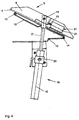
- FIGS. 3 and 4 forth The constructive details for realizing the described Kinematics of the guide flap 4 are shown in FIGS. 3 and 4 forth. Accordingly, the guide flap 4 is about a first pivot axis 12 can be pivoted with a guide flap 4 in the pivoting direction supporting plate 13 supported on one side.
- the support plate 13 is in turn about a second pivot axis 14 with a base plate 15 connected, which in turn on the base frame 1 of the Sheet metal punching machine is attached.
- 14 engages on the guide flap 4 a lifting device in the form of a controllable pneumatic piston-cylinder unit 16.
- a piston rod 17 is on a pivot pin 18 on the stop 9 of the guide flap 4 articulated.
- a swivel connection between a cylinder 19 of the piston-cylinder unit 16 with the base frame 1 of the sheet metal punching machine is via a pivot pin 20 manufactured.
- Another controllable pneumatic piston-cylinder unit 21 is attached to the support plate 13. It includes a firm the support plate 13 connected cylinder 22 and a therein according Figure 3 displaceably guided piston rod in the horizontal direction 23 and serves to interlock the guide flap 4 and the support plate 13.
- the locking pin uses the free end of the piston rod 23 as a locking pin abutment on the guide flap 4 a hole in the stop 9 assigned. Fastening screws 24, 25 hold the Bearing of the pivot pin 20.
- Figure 3 shows the guide flap 4 in the raised position according to Figure 1, in which the sheet metal parts of the collection and transport box 10 are supplied. Should they be at the punching station 8 manufactured sheet metal parts - for example, because of the collection and Transport box 10 is filled or because sheet metal parts with changed Contour can be produced - in the collection and transport box 11 are removed, the guide flap 4 is off their raised position according to Figures 1 and 3 initially operating the piston-cylinder unit 16 in its horizontal Starting position to pivot, in which they are concerned Can store sheet metal parts. Can be connected the guide flap 4 by extending the piston rod 23 of the piston-cylinder unit Lock 21 on the support plate 13. By Operating the piston-cylinder unit 16, the unit is off Guide flap 4 and support plate 13 now in the position according to Figures 2 and 4 pivoted.
- Such locking is dispensable with sufficient Stiffness of those produced via the second pivot axis 14 Pivotal connection between the support plate 13 and the Base plate 15.
- a guide device 103 with a guide element in the form of a Guide flap 104 is used, starting from its horizontal Starting position, in which the manufactured stamped parts are fed be pivotable about a pivot axis 126.
- the Guide flap 104 allows the sheet metal parts to be sorted eject one and the same side of the sheet metal punching machine from this. Differentiate the different discharge directions through their inclination to the horizontal.
- a guide device 203 is also found use of a rocker-type guide flap 204 as a guide element, the one around a distance from opposite edges the guide flap 204 arranged pivot axis 226 is pivotable.
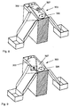
- a guide device 303 as shown in FIGS. 8 and 9 is formed like a switch and comprises as a guide element a pivot lever 327, which on a as a support surface 302 for the sheet metal parts feed chute around a cross pivot axis 326 extending to the support surface 302 is stored. Depending on its swivel position the pivot lever 327 directs the gravity fed to it Sheet metal parts in one or the other discharge direction. Unlike the other guidance systems presented as examples offers the control device 303 to be discharged Sheet metal parts no clipboard.
- a guiding device 403 is used Horizontal conveyor with a than in its direction of movement reversible endless conveyor belt 428 formed guide element, which the sheet metal parts are fed via a feed chute 402 and from which the sheet metal parts temporarily stored on it either on a discharge chute 405 or on a discharge chute 406 are passed.
- control states of the control elements described above - thus the pivot positions of the guide flaps 4, 104, 204, the Swivel position of the swivel lever 327 and the direction of movement of the endless conveyor belt 428 - are by means of the numerical Control of the sheet metal punching machine set automatically.
Landscapes
- Engineering & Computer Science (AREA)
- Mechanical Engineering (AREA)
- Sorting Of Articles (AREA)
- Separation, Sorting, Adjustment, Or Bending Of Sheets To Be Conveyed (AREA)
- Feeding Of Workpieces (AREA)
- Discharge Of Articles From Conveyors (AREA)
Applications Claiming Priority (2)
| Application Number | Priority Date | Filing Date | Title |
|---|---|---|---|
| DE29805197U DE29805197U1 (de) | 1998-03-21 | 1998-03-21 | Vorrichtung zum Sortieren von Werkstückteilen an einer Maschine zum schneidenden Bearbeiten von Werkstücken |
| DE29805197U | 1998-03-21 |
Publications (3)
| Publication Number | Publication Date |
|---|---|
| EP0945196A2 true EP0945196A2 (fr) | 1999-09-29 |
| EP0945196A3 EP0945196A3 (fr) | 2001-08-01 |
| EP0945196B1 EP0945196B1 (fr) | 2004-04-28 |
Family
ID=8054586
Family Applications (1)
| Application Number | Title | Priority Date | Filing Date |
|---|---|---|---|
| EP99105336A Expired - Lifetime EP0945196B1 (fr) | 1998-03-21 | 1999-03-16 | Dispositif pour trier les pièces à d'une machine pour couper des pièces de travail |
Country Status (4)
| Country | Link |
|---|---|
| US (1) | US6168006B1 (fr) |
| EP (1) | EP0945196B1 (fr) |
| AT (1) | ATE265284T1 (fr) |
| DE (2) | DE29805197U1 (fr) |
Cited By (8)
| Publication number | Priority date | Publication date | Assignee | Title |
|---|---|---|---|---|
| CN1081856C (zh) * | 1995-11-29 | 2002-03-27 | 摩托罗拉公司 | 具有分集式接收机的双模无线电用户单元装置及其方法 |
| CN1081855C (zh) * | 1995-11-29 | 2002-03-27 | 摩托罗拉公司 | 无线用户单元中控制分集接收机装置的方法 |
| FR2986171A1 (fr) * | 2012-01-31 | 2013-08-02 | Peugeot Citroen Automobiles Sa | Installation de manutention d'articles comprenant un dispositif de triage gauche/droite. |
| CN104190811A (zh) * | 2014-08-12 | 2014-12-10 | 苏州奥林五金有限公司 | 合页片加工装置 |
| CN104190773A (zh) * | 2014-08-12 | 2014-12-10 | 苏州奥林五金有限公司 | 新型合页片加工装置 |
| EP3106241A1 (fr) | 2015-06-19 | 2016-12-21 | TRUMPF Werkzeugmaschinen GmbH + Co. KG | Machine-outil et procédé destinés a l'évacuation de parties d'une pièce à usiner |
| CN108555173A (zh) * | 2018-05-03 | 2018-09-21 | 安徽云帆科技咨询有限公司 | 一种冲压机械模具废料清除装置 |
| CN113664118A (zh) * | 2020-08-28 | 2021-11-19 | 辰溪成金石业有限公司 | 一种模具加工厂用废料清理设备 |
Families Citing this family (14)
| Publication number | Priority date | Publication date | Assignee | Title |
|---|---|---|---|---|
| US6499582B1 (en) * | 1999-04-05 | 2002-12-31 | Crisplant Inc. | Chute |
| US6481560B2 (en) * | 2000-06-08 | 2002-11-19 | Christopher L. Kearney | Robotic feeding system |
| US6439367B1 (en) * | 2000-12-01 | 2002-08-27 | Lockhead Martin Corporation | Bowl diverter |
| US6533099B2 (en) | 2001-03-14 | 2003-03-18 | Hytrol Conveyor Company, Inc. | Article sorting system and method |
| US6564922B1 (en) * | 2001-03-21 | 2003-05-20 | Lockheed Martin Corporation | Flex diverter |
| US8376663B2 (en) * | 2010-03-10 | 2013-02-19 | Mantissa Corporation | Segmented conveyor and air film chute |
| DE102010037885B3 (de) * | 2010-09-30 | 2011-12-15 | Trumpf Sachsen Gmbh | Anordnung und Verfahren zum Abführen von Bearbeitungsprodukten von einer Bearbeitungsmaschine |
| DE102012011360A1 (de) * | 2012-06-11 | 2013-12-12 | FM SYSTEME FÖRDER- UND MONTAGETECHNIK Schmalzhofer GmbH | Schwerkraftzuführungssystem für Transportgut |
| JP6185558B2 (ja) * | 2013-03-08 | 2017-08-23 | 日本発條株式会社 | 旋盤装置用の回収機構および回収機構の制御方法 |
| US10421618B2 (en) | 2017-06-14 | 2019-09-24 | Grow Solutions Tech Llc | Systems and methods for cleaning a tray in a grow pod |
| CN109702082B (zh) * | 2019-02-11 | 2023-07-14 | 威海埠崎机械有限公司 | 自动上料冲压切断折弯生产线 |
| CN110328324B (zh) * | 2019-06-28 | 2021-02-26 | 徐州鑫旭机械制造有限公司 | 一种用于锻件生产用下料装置 |
| CN112222277B (zh) * | 2020-10-27 | 2024-06-07 | 苏州赛腾菱欧智能科技有限公司 | 端子片自动压入切割分类排出机构 |
| DE102020130607A1 (de) * | 2020-11-19 | 2022-05-19 | Trumpf Werkzeugmaschinen Gmbh + Co. Kg | Entladestation für eine Bearbeitungsmaschine sowie Bearbeitungsmaschine zum schneidenden Bearbeiten von rohr- oder stangenförmigen Werkstücken |
Family Cites Families (16)
| Publication number | Priority date | Publication date | Assignee | Title |
|---|---|---|---|---|
| DE435964C (de) | 1926-10-20 | Muehlbauer Ernst | Verteiler-Vorrichtung mit drehbarem Schuettrohr | |
| DE487641C (de) * | 1929-12-12 | Pohlig Akt Ges J | Vorrichtung zum Abwerfen von Foerdergut | |
| US3010160A (en) * | 1959-06-08 | 1961-11-28 | Fiber Controls Corp | Material feeding system |
| GB1153986A (en) * | 1966-06-21 | 1969-06-04 | Walter Robert Watkinson | Improvements relating to guillotine shearing apparatus. |
| FR2001446A1 (fr) * | 1968-02-07 | 1969-09-26 | Morgaardshammar Ab | |
| US3866498A (en) * | 1973-07-30 | 1975-02-18 | David J Jarman | Light duty stacker |
| US3988014A (en) | 1975-03-10 | 1976-10-26 | Wangco Incorporated | Work station assembly |
| US4422815A (en) * | 1982-01-04 | 1983-12-27 | Western Automation Corporation | Machine tool support and discharge apparatus |
| IT8522178V0 (it) * | 1985-06-13 | 1985-06-13 | Mpa Mecc Postale Automat | Dispositivo di smistamento per sistemi convogliatori a nastro. |
| US4765488A (en) * | 1986-06-17 | 1988-08-23 | Moriarty Larry J | Apparatus for sorting items according to detachable characteristics |
| DE3633730A1 (de) * | 1986-10-03 | 1988-04-14 | Fastenrath Fasti Werk | Vorrichtung zum sortieren und transportieren von blechzuschnitten |
| DE3878189D1 (de) * | 1987-12-11 | 1993-03-18 | Siemens Ag | Vorrichtung zur entsorgung von schnellaeuferpressen. |
| DE3832215C2 (de) | 1988-09-22 | 1995-11-30 | Guenzburger Werkzeugmasch | Vorrichtung zum Trennen von Tafeln |
| US5740901A (en) * | 1994-01-03 | 1998-04-21 | Lockheed Martin Corporation | Apparatus and method for handling flow of packages |
| US5701992A (en) * | 1995-06-02 | 1997-12-30 | Daifuku Co., Ltd. | Sorting equipment |
| US5839566A (en) * | 1996-08-30 | 1998-11-24 | United Parcel Service Of America, Inc. | Belt-carried tilt tray sorter |
-
1998
- 1998-03-21 DE DE29805197U patent/DE29805197U1/de not_active Expired - Lifetime
-
1999
- 1999-03-16 AT AT99105336T patent/ATE265284T1/de not_active IP Right Cessation
- 1999-03-16 EP EP99105336A patent/EP0945196B1/fr not_active Expired - Lifetime
- 1999-03-16 DE DE59909282T patent/DE59909282D1/de not_active Expired - Lifetime
- 1999-03-19 US US09/273,242 patent/US6168006B1/en not_active Expired - Lifetime
Cited By (10)
| Publication number | Priority date | Publication date | Assignee | Title |
|---|---|---|---|---|
| CN1081856C (zh) * | 1995-11-29 | 2002-03-27 | 摩托罗拉公司 | 具有分集式接收机的双模无线电用户单元装置及其方法 |
| CN1081855C (zh) * | 1995-11-29 | 2002-03-27 | 摩托罗拉公司 | 无线用户单元中控制分集接收机装置的方法 |
| FR2986171A1 (fr) * | 2012-01-31 | 2013-08-02 | Peugeot Citroen Automobiles Sa | Installation de manutention d'articles comprenant un dispositif de triage gauche/droite. |
| CN104190811A (zh) * | 2014-08-12 | 2014-12-10 | 苏州奥林五金有限公司 | 合页片加工装置 |
| CN104190773A (zh) * | 2014-08-12 | 2014-12-10 | 苏州奥林五金有限公司 | 新型合页片加工装置 |
| EP3106241A1 (fr) | 2015-06-19 | 2016-12-21 | TRUMPF Werkzeugmaschinen GmbH + Co. KG | Machine-outil et procédé destinés a l'évacuation de parties d'une pièce à usiner |
| EP3269468A1 (fr) | 2015-06-19 | 2018-01-17 | TRUMPF Werkzeugmaschinen GmbH + Co. KG | Machine-outil de décharge des pièces d'ouvrage |
| US10625330B2 (en) | 2015-06-19 | 2020-04-21 | Trumpf Werkzeugmaschinen Gmbh + Co. Kg | Machine tools and methods for ejecting workpiece parts |
| CN108555173A (zh) * | 2018-05-03 | 2018-09-21 | 安徽云帆科技咨询有限公司 | 一种冲压机械模具废料清除装置 |
| CN113664118A (zh) * | 2020-08-28 | 2021-11-19 | 辰溪成金石业有限公司 | 一种模具加工厂用废料清理设备 |
Also Published As
| Publication number | Publication date |
|---|---|
| ATE265284T1 (de) | 2004-05-15 |
| EP0945196A3 (fr) | 2001-08-01 |
| US6168006B1 (en) | 2001-01-02 |
| EP0945196B1 (fr) | 2004-04-28 |
| DE29805197U1 (de) | 1998-08-13 |
| DE59909282D1 (de) | 2004-06-03 |
Similar Documents
| Publication | Publication Date | Title |
|---|---|---|
| EP0945196B1 (fr) | Dispositif pour trier les pièces à d'une machine pour couper des pièces de travail | |
| EP3106241B1 (fr) | Machine-outil et procédé destinés a l'évacuation de parties d'une pièce à usiner | |
| DE102006024407B4 (de) | Werkzeugmaschine | |
| EP0906161B1 (fr) | Machine d'usinage pour pieces sous forme de plaques, notamment pour produire des bords plies sur des pieces en tole | |
| EP2722114A1 (fr) | Dispositif de manipulation de pièces, notamment de pièces issues d'opérations de découpe de tôles et agencements mécaniques dotés d'un tel dispositif | |
| WO1986002584A1 (fr) | Dispositif d'estampage | |
| EP1634675A1 (fr) | Machine-outil pourvue d'un socle | |
| DE29701967U1 (de) | Vorrichtung zum Abschneiden von Stahl | |
| EP1389046A1 (fr) | Dispositif permettant d'ecorcher et de depouiller un produit a traiter | |
| DE2441965A1 (de) | Anordnung zum bedienen insbesondere einer einseitig offenen presse | |
| DE3716666C2 (de) | Plattenaufteilanlage mit einer Längssäge und einer Quersäge | |
| EP2184116B1 (fr) | Procédé destiné à évacuer des éléments en tôle de machines de poinçonnage | |
| EP3313624B1 (fr) | Système de chargement pour pièces | |
| DE19615251C2 (de) | Verfahren und Vorrichtung zum Bearbeiten von Werkstücken in einer Gesenkbiegepresse | |
| EP1017890A1 (fr) | Procede et dispositif de separation des torons | |
| EP1748855B1 (fr) | Dispositif pour le deplacement pas a pas de pieces a usiner | |
| DE19948574A1 (de) | Einrichtung zum Vereinzeln und Ausschleusen von in einer Reihe auf einer Rollenbahn abgelegten Stückgütern | |
| EP2325117B1 (fr) | Dispositif de chargement et déchargement d'une unité de traitement dotée de sections | |
| DE102005029239B4 (de) | Artikel-Entladevorrichtung | |
| CH665159A5 (de) | Schleifmaschine. | |
| DE60115666T2 (de) | Verfahren sowie vorrichtung zur entfernung von gestanzten gegenständen aus einer bearbeitungsstation einer mehrfachstanzmaschine | |
| EP0621092B1 (fr) | Dispositif de transfert des pièces dans une presse à plusieurs étapes | |
| EP0847818B1 (fr) | Presse de transfert | |
| DE1948744C3 (de) | Zuführvorrichtung für eine Stanzpresse zum Stanzen von zwei konzentrischen Werkstücken aus Blechhalbzeug | |
| DE1453200A1 (de) | Maschine zum Abrichtholen und Hobeln von Winkelkanten |
Legal Events
| Date | Code | Title | Description |
|---|---|---|---|
| PUAI | Public reference made under article 153(3) epc to a published international application that has entered the european phase |
Free format text: ORIGINAL CODE: 0009012 |
|
| AK | Designated contracting states |
Kind code of ref document: A2 Designated state(s): AT CH DE FI FR GB IT LI |
|
| AX | Request for extension of the european patent |
Free format text: AL;LT;LV;MK;RO;SI |
|
| PUAL | Search report despatched |
Free format text: ORIGINAL CODE: 0009013 |
|
| RIC1 | Information provided on ipc code assigned before grant |
Free format text: 7B 21D 43/20 A, 7B 21D 43/28 B, 7B 23Q 7/00 B, 7B 23Q 7/08 B, 7B 23Q 7/12 B |
|
| AK | Designated contracting states |
Kind code of ref document: A3 Designated state(s): AT BE CH CY DE DK ES FI FR GB GR IE IT LI LU MC NL PT SE |
|
| AX | Request for extension of the european patent |
Free format text: AL;LT;LV;MK;RO;SI |
|
| 17P | Request for examination filed |
Effective date: 20011120 |
|
| AKX | Designation fees paid |
Free format text: AT CH DE FI FR GB IT LI |
|
| 17Q | First examination report despatched |
Effective date: 20030521 |
|
| GRAP | Despatch of communication of intention to grant a patent |
Free format text: ORIGINAL CODE: EPIDOSNIGR1 |
|
| GRAS | Grant fee paid |
Free format text: ORIGINAL CODE: EPIDOSNIGR3 |
|
| GRAA | (expected) grant |
Free format text: ORIGINAL CODE: 0009210 |
|
| AK | Designated contracting states |
Kind code of ref document: B1 Designated state(s): AT CH DE FI FR GB IT LI |
|
| PG25 | Lapsed in a contracting state [announced via postgrant information from national office to epo] |
Ref country code: FI Free format text: LAPSE BECAUSE OF FAILURE TO SUBMIT A TRANSLATION OF THE DESCRIPTION OR TO PAY THE FEE WITHIN THE PRESCRIBED TIME-LIMIT Effective date: 20040428 |
|
| REG | Reference to a national code |
Ref country code: GB Ref legal event code: FG4D Free format text: NOT ENGLISH |
|
| REG | Reference to a national code |
Ref country code: CH Ref legal event code: EP |
|
| REF | Corresponds to: |
Ref document number: 59909282 Country of ref document: DE Date of ref document: 20040603 Kind code of ref document: P |
|
| GBT | Gb: translation of ep patent filed (gb section 77(6)(a)/1977) |
Effective date: 20040726 |
|
| ET | Fr: translation filed | ||
| PLBE | No opposition filed within time limit |
Free format text: ORIGINAL CODE: 0009261 |
|
| STAA | Information on the status of an ep patent application or granted ep patent |
Free format text: STATUS: NO OPPOSITION FILED WITHIN TIME LIMIT |
|
| 26N | No opposition filed |
Effective date: 20050131 |
|
| PGFP | Annual fee paid to national office [announced via postgrant information from national office to epo] |
Ref country code: CH Payment date: 20080304 Year of fee payment: 10 |
|
| PGFP | Annual fee paid to national office [announced via postgrant information from national office to epo] |
Ref country code: IT Payment date: 20080318 Year of fee payment: 10 Ref country code: GB Payment date: 20080307 Year of fee payment: 10 |
|
| PGFP | Annual fee paid to national office [announced via postgrant information from national office to epo] |
Ref country code: AT Payment date: 20080229 Year of fee payment: 10 |
|
| PGFP | Annual fee paid to national office [announced via postgrant information from national office to epo] |
Ref country code: FR Payment date: 20080228 Year of fee payment: 10 |
|
| PG25 | Lapsed in a contracting state [announced via postgrant information from national office to epo] |
Ref country code: AT Free format text: LAPSE BECAUSE OF NON-PAYMENT OF DUE FEES Effective date: 20090316 |
|
| REG | Reference to a national code |
Ref country code: CH Ref legal event code: PL |
|
| GBPC | Gb: european patent ceased through non-payment of renewal fee |
Effective date: 20090316 |
|
| REG | Reference to a national code |
Ref country code: FR Ref legal event code: ST Effective date: 20091130 |
|
| PG25 | Lapsed in a contracting state [announced via postgrant information from national office to epo] |
Ref country code: LI Free format text: LAPSE BECAUSE OF NON-PAYMENT OF DUE FEES Effective date: 20090331 Ref country code: CH Free format text: LAPSE BECAUSE OF NON-PAYMENT OF DUE FEES Effective date: 20090331 |
|
| PG25 | Lapsed in a contracting state [announced via postgrant information from national office to epo] |
Ref country code: GB Free format text: LAPSE BECAUSE OF NON-PAYMENT OF DUE FEES Effective date: 20090316 Ref country code: FR Free format text: LAPSE BECAUSE OF NON-PAYMENT OF DUE FEES Effective date: 20091123 |
|
| PG25 | Lapsed in a contracting state [announced via postgrant information from national office to epo] |
Ref country code: IT Free format text: LAPSE BECAUSE OF NON-PAYMENT OF DUE FEES Effective date: 20090316 |
|
| PGFP | Annual fee paid to national office [announced via postgrant information from national office to epo] |
Ref country code: DE Payment date: 20180322 Year of fee payment: 20 |
|
| REG | Reference to a national code |
Ref country code: DE Ref legal event code: R071 Ref document number: 59909282 Country of ref document: DE |