EP0945231A2 - Verfahren und Vorrichtung zum Positionieren von Wellrohrschläuchen - Google Patents
Verfahren und Vorrichtung zum Positionieren von Wellrohrschläuchen Download PDFInfo
- Publication number
- EP0945231A2 EP0945231A2 EP99105770A EP99105770A EP0945231A2 EP 0945231 A2 EP0945231 A2 EP 0945231A2 EP 99105770 A EP99105770 A EP 99105770A EP 99105770 A EP99105770 A EP 99105770A EP 0945231 A2 EP0945231 A2 EP 0945231A2
- Authority
- EP
- European Patent Office
- Prior art keywords
- corrugated tube
- hose
- positioning
- feed wheel
- sensor
- Prior art date
- Legal status (The legal status is an assumption and is not a legal conclusion. Google has not performed a legal analysis and makes no representation as to the accuracy of the status listed.)
- Granted
Links
- 238000000034 method Methods 0.000 title claims abstract description 9
- 238000005520 cutting process Methods 0.000 claims description 20
- 230000000694 effects Effects 0.000 description 1
- 230000003993 interaction Effects 0.000 description 1
- 230000003287 optical effect Effects 0.000 description 1
- 230000035945 sensitivity Effects 0.000 description 1
Images

Classifications
-
- B—PERFORMING OPERATIONS; TRANSPORTING
- B26—HAND CUTTING TOOLS; CUTTING; SEVERING
- B26D—CUTTING; DETAILS COMMON TO MACHINES FOR PERFORATING, PUNCHING, CUTTING-OUT, STAMPING-OUT OR SEVERING
- B26D5/00—Arrangements for operating and controlling machines or devices for cutting, cutting-out, stamping-out, punching, perforating, or severing by means other than cutting
- B26D5/38—Arrangements for operating and controlling machines or devices for cutting, cutting-out, stamping-out, punching, perforating, or severing by means other than cutting with means operable by the moving work to initiate the cutting action
- B26D5/40—Arrangements for operating and controlling machines or devices for cutting, cutting-out, stamping-out, punching, perforating, or severing by means other than cutting with means operable by the moving work to initiate the cutting action including a metering device
-
- B—PERFORMING OPERATIONS; TRANSPORTING
- B26—HAND CUTTING TOOLS; CUTTING; SEVERING
- B26D—CUTTING; DETAILS COMMON TO MACHINES FOR PERFORATING, PUNCHING, CUTTING-OUT, STAMPING-OUT OR SEVERING
- B26D3/00—Cutting work characterised by the nature of the cut made; Apparatus therefor
- B26D3/16—Cutting rods or tubes transversely
-
- B—PERFORMING OPERATIONS; TRANSPORTING
- B26—HAND CUTTING TOOLS; CUTTING; SEVERING
- B26D—CUTTING; DETAILS COMMON TO MACHINES FOR PERFORATING, PUNCHING, CUTTING-OUT, STAMPING-OUT OR SEVERING
- B26D5/00—Arrangements for operating and controlling machines or devices for cutting, cutting-out, stamping-out, punching, perforating, or severing by means other than cutting
- B26D5/20—Arrangements for operating and controlling machines or devices for cutting, cutting-out, stamping-out, punching, perforating, or severing by means other than cutting with interrelated action between the cutting member and work feed
- B26D5/30—Arrangements for operating and controlling machines or devices for cutting, cutting-out, stamping-out, punching, perforating, or severing by means other than cutting with interrelated action between the cutting member and work feed having the cutting member controlled by scanning a record carrier
- B26D5/32—Arrangements for operating and controlling machines or devices for cutting, cutting-out, stamping-out, punching, perforating, or severing by means other than cutting with interrelated action between the cutting member and work feed having the cutting member controlled by scanning a record carrier with the record carrier formed by the work itself
Definitions
- the invention relates to a method for positioning Corrugated tube hoses, with the steps of transporting one Corrugated tube by means of a transport device and Position the corrugated tube by means of a Transport device interacting sensor device.
- the invention further relates to a device for Position corrugated tube hoses with at least one Feed wheel for a corrugated tube hose, one with a Positioning device interacting with the sensor Corrugated tube, and a cutter.
- One formed from at least one feed wheel Feed device is designed to take hoses with both smoother and wavy ones Position the outer skin in such a way that the hose can be positioned using the Cutting device into sections with a given length is cuttable.
- a accurate positioning of a hose that through Interaction of a mostly optical sensor, the one relative position of a hose end to Cutting device senses with the Positioning device that the hose inside the Device by means of at least one feed wheel formed feed device for the purpose of cutting the Laterally displaced and then fixed is too imprecise for many applications.
- This Disadvantage of the conventional devices is under Maintaining the conventional positioning process only with a considerable expense through numerical controls reachable.
- the object of the invention is to provide a method with the exact positioning of a corrugated tube for the purpose of cutting the corrugated tube Predeterminable lengths can be efficiently achieved in a simple manner becomes.
- the object of the invention is also a Positioning device especially for corrugated tube hoses create with the precise positioning of a Corrugated tube hose for the purpose of cutting the Corrugated tube hose to predetermined lengths in a simple way is achieved efficiently.
- This task becomes for the above-mentioned procedure achieved in that when transporting the Corrugated tube hose activated at least one feed wheel is the one on the shaft distance of the corrugated tube has adapted external toothing, which in the troughs of the Waves of the corrugated tube hose engages, and at Position the corrugated tube with the feed wheel an indicator device cooperates.
- External teeth on the at least one feed wheel which in engages the troughs of the corrugated tube hose and together with one coupled to the feed wheel Indicator device acts as a positioning device, achieves that a predetermined positioning and then fixing a corrugated tube in the Device by means of the at least one feed wheel directly at a relative rotational position of the at least one Feed wheel is readable or sensible.
- At least a feed wheel preferably has one for this purpose Marking or indicator device on the Sensor is arranged so that it is in any rotational position the feed wheel can be sensed by the sensor.
- the sensitivity of the sensor device is can be increased in a simple manner, that the marking or indicator device in the area of Periphery of the at least one feed wheel arranged and the feed wheel with the largest possible Diameter is provided.
- the device according to the invention are two feed wheels provided between which the corrugated tube hose is guided is. This ensures that the lateral to transporting corrugated tube from two engaging in opposite directions opposite feed wheels can be moved, thereby creating a ensures symmetrical action of frictional forces is and thus a particularly uniform mobility of the Corrugated tube hose is reached.
- the invention Device is in the range of at least one Feed wheel of a guide of the corrugated tube intended.
- the leadership can be done in different ways Embodiments may be provided, with only their Effect is important to put a corrugated tube hose exactly in Direction of transport of the at least one feed wheel orient and a sag or a turn off to prevent this direction.
- the leadership can do this a plurality of rollers or webs can be formed, or it can be formed in the form of a buckling tube section be. In any case, it has cutouts in which the at least one feed wheel, preferably two Feed wheels, engage in a corrugated tube and at least one further recess through which an access a cutting device for the corrugated tube is guaranteed.
- the leadership is preferably essentially as Hollow cylinder executed, the inner diameter for conclusive, reproducible management of a Corrugated tube hose is designed. This will make one particularly precise guidance of a corrugated tube hose achieved.
- the device according to the invention is in one end of a Corrugated tube hose insertable support mandrel provided, whose outer diameter is dimensioned so that it is inside of the corrugated tube hose is conclusively reproducible.
- the Support mandrel serves the purpose of collapsing one Corrugated tube hose when cutting using the Prevent cutting device and thus its natural shape even during a cutting process by means of the cutting device.
- the Support mandrel is preferably made of two to each other spaced partial mandrels formed over at least a web are connected. This will turn on created a simple way a support mandrel that a Has recess in which the cutter a cutting process of a corrugated tube can be inserted is to make a uniform cut of the corrugated tube ensure.
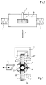
- Embodiment of the positioning and Cutting device is a corrugated tube 7 in one Corrugated pipe guide 4 reciprocally supported, where an upper feed wheel 2, one on the shaft distance of the corrugated tube hose has adapted external teeth 13 and driven via an axis 2 ', and a lower one Feed wheel 3, which also with a Adjusted shaft distance of the corrugated tube 7 External toothing 13 is provided and via an axis 3 ' is driven by recesses 11 and 11 'in the Corrugated pipe guide 4 are guided such that the External teeth 13 of the feed wheels 2 and 3 in the Intervene troughs of the waves of the corrugated tube 7.
- a marking or indicator device 14 is provided, which is firmly connected to the feed wheel 2, and together with a sensor 1 as a positioning device for the Corrugated tube 7 acts in the relative position a portion of the corrugated tube 7 to a Recess 12 in the corrugated pipe guide 4, in one Reciprocably mounted cutting device 11 for Carrying out a cutting process for the corrugated tube 7 is insertable, predeterminable and fixable.
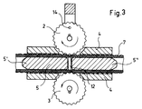
- FIG 3 is an embodiment of the invention Positioning and cutting device shown at which instead of a corrugated tube hose 7 with a hose 7 smooth surface is transportable.
- the feed wheels 2 and 3 have pointed ends that partly in the elastic surface material of the Intervene hose to transport the hose 7 and lock.
Landscapes
- Life Sciences & Earth Sciences (AREA)
- Forests & Forestry (AREA)
- Engineering & Computer Science (AREA)
- Mechanical Engineering (AREA)
- Rigid Pipes And Flexible Pipes (AREA)
- Shaping Of Tube Ends By Bending Or Straightening (AREA)
- Length Measuring Devices Characterised By Use Of Acoustic Means (AREA)
- Investigating Or Analyzing Materials By The Use Of Ultrasonic Waves (AREA)
- Lining Or Joining Of Plastics Or The Like (AREA)
Abstract
Description
- Fig.1
- eine schematische Ansicht einer bevorzugten Ausführungsform der erfindungsgemäßen Vorrichtung in einer Ansicht von oben;
- Fig.2
- die in Figur 1 dargestellte Ausführungsform der erfindungsgemäßen Vorrichtung in einer Querschnittsansicht;
- Fig.3
- die in den Figuren 1 und 2 dargestellte Ausführungsform der erfindungsgemäßen Vorrichtung in einer Längsschnittansicht;
- Fig.3a
- eine weitere Ausführungsform der erfindungsgemäßen Vorrichtung in einer Längsschnittansicht entsprechend Fig. 3;
- Fig.4
- eine Querschnittsansicht eines in der Vorrichtung gemäß den Figuren 1 bis 3 transportierten Wellrohrschlauches einschließlich Führungsrohr und Führungsdorn.
Claims (8)
- Vorrichtung zum Positionieren von Wellrohrschläuchen, mit mindestens einem Vorschubrad für einen Wellrohrschlauch, einer mit einem Sensor zusammenwirkenden Positioniereinrichtung für den Wellrohrschlauch, und einer Schneideeinrichtung, dadurch gekennzeichnet, daß mindestens ein Vorschubrad einer auf den Wellenabstand des Wellrohrschlauches angepaßte Außenzahnung aufweist, die in die Wellentäler der Wellen des Wellrohrschlauches eingreift, und zusammen mit einer mit dem mindestens einen Vorschubrad gekoppelten Indikatoreinrichtung als Positioniereinrichtung wirkt.
- Vorrichtung nach Anspruch 1, dadurch gekennzeichnet, daß die Indikatoreinrichtung und der Sensor so positioniert sind, daß die Indikatoreinrichtung von dem Sensor sensierbar ist.
- Vorrichtung nach einem der vorhergehenden Ansprüche, dadurch gekennzeichnet, daß zwei Vorschubräder vorgesehen sind, zwischen denen der Wellrohrschlauch geführt ist.
- Vorrichtung nach einem der vorhergehenden Ansprüche, dadurch gekennzeichnet, daß im Bereich des mindestens einen Vorschubrades eine Führung für den Wellrohrschlauch vorgesehen ist.
- Vorrichtung nach Anspruch 4, dadurch gekennzeichnet, daß die Führung im wesentlichen als Hohlzylinder ausgeführt ist, dessen Innendurchmesser zur schlüssigen reziprozierbaren Führung des Wellrohrschlauches ausgelegt ist.
- Vorrichtung nach einem der vorhergehenden Ansprüche, dadurch gekennzeichnet, daß ein in ein Ende des Wellrohrschlauches einschiebbarer Stützdorn vorgesehen ist, dessen Außendurchmesser so bemessen ist, daß er im Inneren des Wellrohrschlauches schlüssig reproduzierbar ist.
- Vorrichtung nach Anspruch 6, dadurch gekennzeichnet, daß der Stützdorn aus zwei zueinander beabstandeten Teildornen gebildet ist, die über einen Steg miteinander verbunden sind.
- Verfahren zum Positionieren von Wellrohrschläuchen, mit folgenden Schritten:Transportieren eines Wellrohrschlauches mittels einer Transporteinrichtung,Positionieren des Wellrohrschlauches mittels einer mit der Transporteinrichtung zusammenwirkenden Sensoreinrichtung, dadurch gekennzeichnet, daßbeim Transportieren des Wellrohrschlauches mindestens ein Vorschubrad aktiviert wird, das eine auf den Wellenabstand des Wellrohrschlauches angepaßte Außenzahnung aufweist, die in die Wellentäler der Wellen des Wellrohrschlauches eingreift, undbeim Positionieren des Wellrohrschlauches das Vorschubrad mit einer Indikatoreinrichtung zusammenwirkt.
Applications Claiming Priority (2)
| Application Number | Priority Date | Filing Date | Title |
|---|---|---|---|
| DE19812524 | 1998-03-21 | ||
| DE19812524A DE19812524C2 (de) | 1998-03-21 | 1998-03-21 | Vorrichtung zum Positionieren von Wellrohrschläuchen |
Publications (3)
| Publication Number | Publication Date |
|---|---|
| EP0945231A2 true EP0945231A2 (de) | 1999-09-29 |
| EP0945231A3 EP0945231A3 (de) | 2001-04-11 |
| EP0945231B1 EP0945231B1 (de) | 2002-10-09 |
Family
ID=7861858
Family Applications (1)
| Application Number | Title | Priority Date | Filing Date |
|---|---|---|---|
| EP99105770A Expired - Lifetime EP0945231B1 (de) | 1998-03-21 | 1999-03-22 | Verfahren und Vorrichtung zum Positionieren von Wellrohrschläuchen |
Country Status (4)
| Country | Link |
|---|---|
| EP (1) | EP0945231B1 (de) |
| AT (1) | ATE225698T1 (de) |
| DE (2) | DE19812524C2 (de) |
| ES (1) | ES2186270T3 (de) |
Cited By (6)
| Publication number | Priority date | Publication date | Assignee | Title |
|---|---|---|---|---|
| CN104596460A (zh) * | 2014-12-04 | 2015-05-06 | 北京福田戴姆勒汽车有限公司 | 一种波纹管的长度测量装置及方法 |
| CN104848765A (zh) * | 2014-09-11 | 2015-08-19 | 无锡市威特机械有限公司 | 一种挤出机棒料长度检测和推料装置 |
| CN105562808A (zh) * | 2016-02-25 | 2016-05-11 | 永康市合旺自动化设备有限公司 | 波纹管切断机 |
| CN108955581A (zh) * | 2018-09-25 | 2018-12-07 | 李童 | 波纹管定位装置及其使用方法 |
| CN109093704A (zh) * | 2018-08-01 | 2018-12-28 | 安徽海蚨祥橡胶有限公司 | 一种塑料管材制品用定长切割控制装置 |
| US20240009023A1 (en) * | 2020-08-11 | 2024-01-11 | Purewick Corporation | Fluid collection devices and methods of manufacturing same |
Families Citing this family (3)
| Publication number | Priority date | Publication date | Assignee | Title |
|---|---|---|---|---|
| DE10229081B4 (de) * | 2002-06-28 | 2007-07-19 | Contitech Luftfedersysteme Gmbh | Verfahren zum Trennen von Schläuchen und Vorrichtung zur Durchführung des Verfahrens |
| DE10229080A1 (de) * | 2002-06-28 | 2004-01-29 | Contitech Luftfedersysteme Gmbh | Vorrichtung und Verfahren zum Zuschneiden schlauchförmiger Erzeugnisse |
| DE102005005508B4 (de) * | 2005-02-04 | 2017-05-11 | Battenfeld-Cincinnati Germany Gmbh | Verfahren und Vorrichtung zum Trennen eines Extrudates |
Family Cites Families (8)
| Publication number | Priority date | Publication date | Assignee | Title |
|---|---|---|---|---|
| US3843758A (en) * | 1972-07-13 | 1974-10-22 | Plastic Tubing | Method for making and slitting plastic corrugated tubes |
| US3916763A (en) * | 1972-07-13 | 1975-11-04 | Ernest J Maroschak | Apparatus for forming slits in tubes |
| US3957386A (en) * | 1975-02-18 | 1976-05-18 | Lupke Manfred Arno Alfred | Corrugated tubing perforating machine |
| CA1060775A (en) * | 1977-03-18 | 1979-08-21 | Manfred A.A. Lupke | Apparatus for perforating tubing |
| FR2383742A1 (fr) * | 1977-03-18 | 1978-10-13 | Lupke Gerd Paul Heinrich | Appareil et procede de perforation de tubes, et procede de fabrication d'une partie de cet appareil |
| DE3426680A1 (de) * | 1984-07-19 | 1986-01-23 | Fränkische Rohrwerke Gebrüder Kirchner GmbH & Co, 8729 Königsberg | Vorrichtung zum herstellen von kunststoffschlaeuchen |
| US5572917A (en) * | 1992-02-05 | 1996-11-12 | Truemner; Dale | Apparatus for perforating corrugated tubing at high speeds and method of using same |
| DE9406849U1 (de) * | 1994-04-23 | 1994-07-14 | Göstl, Helmut, 87746 Erkheim | Vorrichtung zum Steuern von elektrischen Signalen für den Modellbau |
-
1998
- 1998-03-21 DE DE19812524A patent/DE19812524C2/de not_active Expired - Lifetime
-
1999
- 1999-03-22 EP EP99105770A patent/EP0945231B1/de not_active Expired - Lifetime
- 1999-03-22 AT AT99105770T patent/ATE225698T1/de not_active IP Right Cessation
- 1999-03-22 DE DE59902993T patent/DE59902993D1/de not_active Expired - Lifetime
- 1999-03-22 ES ES99105770T patent/ES2186270T3/es not_active Expired - Lifetime
Non-Patent Citations (1)
| Title |
|---|
| None |
Cited By (8)
| Publication number | Priority date | Publication date | Assignee | Title |
|---|---|---|---|---|
| CN104848765A (zh) * | 2014-09-11 | 2015-08-19 | 无锡市威特机械有限公司 | 一种挤出机棒料长度检测和推料装置 |
| CN104848765B (zh) * | 2014-09-11 | 2017-12-22 | 无锡市威特机械有限公司 | 一种挤出机棒料长度检测和推料装置 |
| CN104596460A (zh) * | 2014-12-04 | 2015-05-06 | 北京福田戴姆勒汽车有限公司 | 一种波纹管的长度测量装置及方法 |
| CN105562808A (zh) * | 2016-02-25 | 2016-05-11 | 永康市合旺自动化设备有限公司 | 波纹管切断机 |
| CN109093704A (zh) * | 2018-08-01 | 2018-12-28 | 安徽海蚨祥橡胶有限公司 | 一种塑料管材制品用定长切割控制装置 |
| CN108955581A (zh) * | 2018-09-25 | 2018-12-07 | 李童 | 波纹管定位装置及其使用方法 |
| CN108955581B (zh) * | 2018-09-25 | 2024-05-03 | 李童 | 波纹管定位装置及其使用方法 |
| US20240009023A1 (en) * | 2020-08-11 | 2024-01-11 | Purewick Corporation | Fluid collection devices and methods of manufacturing same |
Also Published As
| Publication number | Publication date |
|---|---|
| ES2186270T3 (es) | 2003-05-01 |
| EP0945231B1 (de) | 2002-10-09 |
| EP0945231A3 (de) | 2001-04-11 |
| ATE225698T1 (de) | 2002-10-15 |
| DE19812524A1 (de) | 1999-09-30 |
| DE19812524C2 (de) | 2001-07-05 |
| DE59902993D1 (de) | 2002-11-14 |
Similar Documents
| Publication | Publication Date | Title |
|---|---|---|
| EP0005444B1 (de) | Wickelkopf | |
| EP2896844A1 (de) | Verfahren und Vorrichtung zum Herstellen eines Wälzlagerkäfigs | |
| EP0945231B1 (de) | Verfahren und Vorrichtung zum Positionieren von Wellrohrschläuchen | |
| DE2952026A1 (de) | Biegemaschine zum gleichzeitigen biegen von betonstahldraehten bei baustahlmatten | |
| EP0470354A1 (de) | Bohrer zur Herstellung von zylindrischen Bohrlöchern | |
| EP0622136B1 (de) | Vorrichtung zur Herstellung von Bewehrungsgittern für Betonplatten | |
| DE2800079A1 (de) | Vorrichtung zur herstellung von flanschen an rohren | |
| EP3552785B1 (de) | Vorrichtung und verfahren zum schneiden eines leerrohrs | |
| EP0439830A2 (de) | Vorrichtung zur Be- oder Verarbeitung einer Materialbahn | |
| DE2009509C3 (de) | Maschine zur kontinuierlichen Herstellung von Bewehrungskörben für Pfähle, Masten o.dgl. aus Stahlbeton | |
| EP0465767B1 (de) | Gründungspfahl aus armiertem Beton | |
| DE3626323C1 (en) | Cutting device for flexible tubes with spiral wire reinforcement | |
| DE2901141A1 (de) | Vorrichtung zum zuschneiden eines metallstreifens bei der herstellung von aus einem spiralfoermig aufgewundenen metallstreifen hergestellten rohren | |
| DE29823651U1 (de) | Vorrichtung zum Positionieren von Wellrohrschläuchen | |
| DE2548853B2 (de) | Vorrichtung zur Herstellung von metallenen Ringrohlingen | |
| DE2108338B2 (de) | Schneidvorrichtung zum Unterteilen kontinuierlich angelieferter Material-Stränge | |
| DE3920974A1 (de) | Vorrichtung zur vorkalibrierung von zylindrischen, gehaeusefoermigen elementen fuer kontinuierlich arbeitende schweissmaschinen | |
| EP0785831B1 (de) | Verfahren zur herstellung eines metallischen hohlkörpers, nach diesem verfahren hergestellter hohlkörper und einrichtung zur durchführung dieses verfahrens | |
| DE3504433C2 (de) | ||
| DE19611435C2 (de) | Integrierte Einstellhilfe für Teleskopstützen und Verfahren zu deren Herstellung | |
| DE10030499B4 (de) | Montageeinheit zur Herstellung einer Tragzelle eines Luftschiffs | |
| DE19906201B4 (de) | Vorrichtung zur Befestigung eines Fadens an einer chirurgischen Nadel | |
| EP0765981B1 (de) | Integrierte Einstellhilfe für Teleskopstützen und Verfahren zu deren Herstellung | |
| DE10242883B4 (de) | Schneidvorrichtung zum gekrümmten Schneiden von Papier | |
| DE2550617B2 (de) | Vorrichtung zur Herstellung von metallenen Ringrohlingen |
Legal Events
| Date | Code | Title | Description |
|---|---|---|---|
| PUAI | Public reference made under article 153(3) epc to a published international application that has entered the european phase |
Free format text: ORIGINAL CODE: 0009012 |
|
| AK | Designated contracting states |
Kind code of ref document: A2 Designated state(s): AT CH DE ES FR GB IT LI |
|
| AX | Request for extension of the european patent |
Free format text: AL;LT;LV;MK;RO;SI |
|
| PUAL | Search report despatched |
Free format text: ORIGINAL CODE: 0009013 |
|
| AK | Designated contracting states |
Kind code of ref document: A3 Designated state(s): AT BE CH CY DE DK ES FI FR GB GR IE IT LI LU MC NL PT SE |
|
| AX | Request for extension of the european patent |
Free format text: AL;LT;LV;MK;RO;SI |
|
| RIC1 | Information provided on ipc code assigned before grant |
Free format text: 7B 26D 5/40 A, 7B 26D 3/16 B, 7B 26D 7/01 B |
|
| 17P | Request for examination filed |
Effective date: 20010908 |
|
| AKX | Designation fees paid |
Free format text: AT CH DE ES FR GB IT LI |
|
| GRAG | Despatch of communication of intention to grant |
Free format text: ORIGINAL CODE: EPIDOS AGRA |
|
| 17Q | First examination report despatched |
Effective date: 20020115 |
|
| GRAG | Despatch of communication of intention to grant |
Free format text: ORIGINAL CODE: EPIDOS AGRA |
|
| GRAH | Despatch of communication of intention to grant a patent |
Free format text: ORIGINAL CODE: EPIDOS IGRA |
|
| GRAH | Despatch of communication of intention to grant a patent |
Free format text: ORIGINAL CODE: EPIDOS IGRA |
|
| GRAA | (expected) grant |
Free format text: ORIGINAL CODE: 0009210 |
|
| AK | Designated contracting states |
Kind code of ref document: B1 Designated state(s): AT CH DE ES FR GB IT LI |
|
| REF | Corresponds to: |
Ref document number: 225698 Country of ref document: AT Date of ref document: 20021015 Kind code of ref document: T |
|
| REG | Reference to a national code |
Ref country code: GB Ref legal event code: FG4D Free format text: NOT ENGLISH |
|
| REG | Reference to a national code |
Ref country code: CH Ref legal event code: EP |
|
| REF | Corresponds to: |
Ref document number: 59902993 Country of ref document: DE Date of ref document: 20021114 |
|
| GBT | Gb: translation of ep patent filed (gb section 77(6)(a)/1977) |
Effective date: 20030128 |
|
| REG | Reference to a national code |
Ref country code: CH Ref legal event code: NV Representative=s name: ISLER & PEDRAZZINI AG |
|
| REG | Reference to a national code |
Ref country code: ES Ref legal event code: FG2A Ref document number: 2186270 Country of ref document: ES Kind code of ref document: T3 |
|
| ET | Fr: translation filed | ||
| PLBE | No opposition filed within time limit |
Free format text: ORIGINAL CODE: 0009261 |
|
| STAA | Information on the status of an ep patent application or granted ep patent |
Free format text: STATUS: NO OPPOSITION FILED WITHIN TIME LIMIT |
|
| 26N | No opposition filed |
Effective date: 20030710 |
|
| PGFP | Annual fee paid to national office [announced via postgrant information from national office to epo] |
Ref country code: GB Payment date: 20050311 Year of fee payment: 7 |
|
| PGFP | Annual fee paid to national office [announced via postgrant information from national office to epo] |
Ref country code: FR Payment date: 20050324 Year of fee payment: 7 Ref country code: AT Payment date: 20050324 Year of fee payment: 7 |
|
| PGFP | Annual fee paid to national office [announced via postgrant information from national office to epo] |
Ref country code: ES Payment date: 20050330 Year of fee payment: 7 |
|
| PG25 | Lapsed in a contracting state [announced via postgrant information from national office to epo] |
Ref country code: GB Free format text: LAPSE BECAUSE OF NON-PAYMENT OF DUE FEES Effective date: 20060322 Ref country code: AT Free format text: LAPSE BECAUSE OF NON-PAYMENT OF DUE FEES Effective date: 20060322 |
|
| PG25 | Lapsed in a contracting state [announced via postgrant information from national office to epo] |
Ref country code: ES Free format text: LAPSE BECAUSE OF NON-PAYMENT OF DUE FEES Effective date: 20060323 |
|
| GBPC | Gb: european patent ceased through non-payment of renewal fee |
Effective date: 20060322 |
|
| REG | Reference to a national code |
Ref country code: FR Ref legal event code: ST Effective date: 20061130 |
|
| REG | Reference to a national code |
Ref country code: ES Ref legal event code: FD2A Effective date: 20060323 |
|
| REG | Reference to a national code |
Ref country code: CH Ref legal event code: PCAR Free format text: ISLER & PEDRAZZINI AG;POSTFACH 1772;8027 ZUERICH (CH) |
|
| PG25 | Lapsed in a contracting state [announced via postgrant information from national office to epo] |
Ref country code: FR Free format text: LAPSE BECAUSE OF NON-PAYMENT OF DUE FEES Effective date: 20060331 |
|
| PG25 | Lapsed in a contracting state [announced via postgrant information from national office to epo] |
Ref country code: IT Free format text: LAPSE BECAUSE OF NON-PAYMENT OF DUE FEES Effective date: 20100322 |
|
| PGRI | Patent reinstated in contracting state [announced from national office to epo] |
Ref country code: IT Effective date: 20110616 |
|
| REG | Reference to a national code |
Ref country code: DE Ref legal event code: R082 Ref document number: 59902993 Country of ref document: DE Representative=s name: LORENZ & KOLLEGEN PATENTANWAELTE PARTNERSCHAFT, DE |
|
| REG | Reference to a national code |
Ref country code: DE Ref legal event code: R082 Ref document number: 59902993 Country of ref document: DE Representative=s name: LORENZ & KOLLEGEN PATENTANWAELTE PARTNERSCHAFT, DE Effective date: 20110927 Ref country code: DE Ref legal event code: R081 Ref document number: 59902993 Country of ref document: DE Owner name: RAUCH, GERHARD, DE Free format text: FORMER OWNER: METZNER, KLAUS, 89614 OEPFINGEN, DE Effective date: 20110927 |
|
| REG | Reference to a national code |
Ref country code: CH Ref legal event code: PUE Owner name: GERHARD RAUCH Free format text: METZNER, KLAUS#HAUPTSTRASSE 44#89614 OEPFINGEN (DE) -TRANSFER TO- GERHARD RAUCH#LAEMMERWEG 33#89079 ULM (DE) Ref country code: CH Ref legal event code: NV Representative=s name: CABINET ROLAND NITHARDT CONSEILS EN PROPRIETE INDU |
|
| PGFP | Annual fee paid to national office [announced via postgrant information from national office to epo] |
Ref country code: CH Payment date: 20180621 Year of fee payment: 20 Ref country code: DE Payment date: 20180329 Year of fee payment: 20 |
|
| PGFP | Annual fee paid to national office [announced via postgrant information from national office to epo] |
Ref country code: IT Payment date: 20180329 Year of fee payment: 20 |
|
| REG | Reference to a national code |
Ref country code: DE Ref legal event code: R071 Ref document number: 59902993 Country of ref document: DE |
|
| REG | Reference to a national code |
Ref country code: CH Ref legal event code: PL |