EP0945239A2 - Procédé et installation pour la fabrication de murs - Google Patents
Procédé et installation pour la fabrication de murs Download PDFInfo
- Publication number
- EP0945239A2 EP0945239A2 EP99105929A EP99105929A EP0945239A2 EP 0945239 A2 EP0945239 A2 EP 0945239A2 EP 99105929 A EP99105929 A EP 99105929A EP 99105929 A EP99105929 A EP 99105929A EP 0945239 A2 EP0945239 A2 EP 0945239A2
- Authority
- EP
- European Patent Office
- Prior art keywords
- wall
- masonry
- mortar
- bricks
- supply
- Prior art date
- Legal status (The legal status is an assumption and is not a legal conclusion. Google has not performed a legal analysis and makes no representation as to the accuracy of the status listed.)
- Withdrawn
Links
Images


Classifications
-
- B—PERFORMING OPERATIONS; TRANSPORTING
- B28—WORKING CEMENT, CLAY, OR STONE
- B28B—SHAPING CLAY OR OTHER CERAMIC COMPOSITIONS; SHAPING SLAG; SHAPING MIXTURES CONTAINING CEMENTITIOUS MATERIAL, e.g. PLASTER
- B28B15/00—General arrangement or layout of plant ; Industrial outlines or plant installations
-
- B—PERFORMING OPERATIONS; TRANSPORTING
- B28—WORKING CEMENT, CLAY, OR STONE
- B28B—SHAPING CLAY OR OTHER CERAMIC COMPOSITIONS; SHAPING SLAG; SHAPING MIXTURES CONTAINING CEMENTITIOUS MATERIAL, e.g. PLASTER
- B28B11/00—Apparatus or processes for treating or working the shaped or preshaped articles
-
- E—FIXED CONSTRUCTIONS
- E04—BUILDING
- E04C—STRUCTURAL ELEMENTS; BUILDING MATERIALS
- E04C2/00—Building elements of relatively thin form for the construction of parts of buildings, e.g. sheet materials, slabs, or panels
- E04C2/02—Building elements of relatively thin form for the construction of parts of buildings, e.g. sheet materials, slabs, or panels characterised by specified materials
- E04C2/04—Building elements of relatively thin form for the construction of parts of buildings, e.g. sheet materials, slabs, or panels characterised by specified materials of concrete or other stone-like material; of asbestos cement; of cement and other mineral fibres
- E04C2/041—Building elements of relatively thin form for the construction of parts of buildings, e.g. sheet materials, slabs, or panels characterised by specified materials of concrete or other stone-like material; of asbestos cement; of cement and other mineral fibres composed of a number of smaller elements, e.g. bricks, also combined with a slab of hardenable material
- E04C2/042—Apparatus for handling the smaller elements or the hardenable material; bricklaying machines for prefabricated panels
-
- E—FIXED CONSTRUCTIONS
- E04—BUILDING
- E04G—SCAFFOLDING; FORMS; SHUTTERING; BUILDING IMPLEMENTS OR AIDS, OR THEIR USE; HANDLING BUILDING MATERIALS ON THE SITE; REPAIRING, BREAKING-UP OR OTHER WORK ON EXISTING BUILDINGS
- E04G21/00—Preparing, conveying, or working-up building materials or building elements in situ; Other devices or measures for constructional work
- E04G21/14—Conveying or assembling building elements
- E04G21/16—Tools or apparatus
- E04G21/20—Tools or apparatus for applying mortar
- E04G21/204—Mortar sledges
Definitions
- the invention relates to a method for producing Masonry, especially prefabricated masonry, with a mobile Masonry, the layered wall elements below Consideration of the planned openings for doors and Windows created, as well as a device for carrying out of the procedure.
- DE 28 29 863 A1 describes a device for manufacturing of vertical wall panels made of bricks known with a scaffold arranged on wheels.
- the the entire scaffold moves in the longitudinal direction of a hall, whereas the brickwork moves in the transverse direction and thus wall elements defined in terms of size and shape in the transverse direction of the hall.
- the object of the present invention is a method for the production of masonry, especially prefabricated masonry to create which is very flexible and through which masonry with a high quality associated with a high output can be produced.
- the associated Device is said to be a relatively straightforward Have structure.
- This object is achieved in that several wall elements in one step in the form of a continuous masonry wall made of bricks on a Underlay are made, and that the masonry wall after curing at predefined locations in individual Wall elements is separated, after which the individual wall elements lifted off the surface and ready for rework and / or transported to the installation site for transport become.
- the wall device can be provided that the mortar is mixed on the wall device, or alternatively, that the mortar in mixed condition on the wall device is loaded.
- a very dimensionally accurate masonry wall is obtained when the beginning and end of the masonry wall and openings for windows and doors determined by an optoelectronic length measuring system become.
- the individual wall elements can be made very accurately if the position of the separation points for the individual wall elements through the optoelectronic length measuring system be determined.
- a constructive solution to the above problem results themselves in that the wall device on parallel to the masonry wall to be made on a base extending rails is movable, the wall device at least at one end for moving and / or for filling up the stone supply and / or the mortar application device is traversable, and that for separating in individual wall elements a mobile sawing device and to remove the cut wall elements Extending device are provided.
- the continuous masonry wall on any Place Due to the mobile sawing device, it is according to the invention possible, the continuous masonry wall on any Place to separate.
- the extension device according to the invention takes over the removal of the cut wall elements, without affecting the manufacture of the masonry wall.
- the sawing device is arranged on the extension device is an additional device for the procedure of Sawing device can be saved.
- a structurally very simple way to set up the wall to be transported to the next masonry wall is achieved when to cross-move the brickwork a traversing device movable on rails is provided is.
- the displacement gripper in the height is adjustable, making the masonry as well can be manufactured easily and precisely.
- the removal of the finished wall elements is very easy possible if the exit car is on one on the opposite Arranged side of the first transverse displacement device second traversing device is mobile.
- the pad with several in the transverse direction the recesses running along the masonry wall is in which support devices for the to be created Masonry wall can be inserted, which upwards protrude beyond the recesses.
- Such a structure of the pad according to the invention enables on the one hand a complete cut through the Masonry wall through the sawing device without this must be moved in the horizontal direction. On the other hand can thereby on conventional hitherto supporting devices the individual wall elements can be dispensed with, since the wall element in a simple manner at its bottom from the Pad is removable.
- the cover can be done in a simple and inexpensive manner through one or more foils and / or bitumen sheets and / or narrow-mesh fabric strips are formed.
- the support devices are designed as wooden slats.
- extension car is equipped with tines, its width is less than between the support devices themselves gaps, there is a simple way to transport the cut wall element further.
- the mortar applicator is a screw conveyor through which mortar towards an opening of the mortar applicator is eligible, one results Forced delivery of the mortar and thus safe application of the mortar on the masonry wall.
- the opening can be closed by a slide device be, which has at least one slide.
- slide device can be provided that these several side by side arranged slider.
- the reinforcing mesh can combine very well with the mortar.
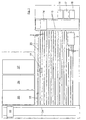
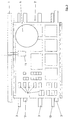
- Fig. 1 and Fig. 2 are several, parallel to each other arranged masonry walls 1 shown. These will through a wall device 2 also parallel to each other arranged documents 3 by stacking individual bricks 4 made. The documents 3 are only in Fig. 2 below two masonry walls 1 indicated.
- the wall device 2 there is a height-adjustable floor 5 the wall device 2, a stock of bricks 4, a Dry mortar silo designed in a manner known per se 6 with a mortar applicator arranged thereon.
- a mortar supply 8 In the dry mortar silo 6 is a mortar supply 8.
- the mortar is mixed in a known manner Supply of a water supply that is in a suitable, container, not shown.
- the mortar can also be mixed with water mixed state on the wall device 2, e.g. in the Mortar applicator 7 are located.
- a displacement gripper also arranged on the wall device 2 11 grabs the required bricks 4 and through the mortar applicator 7 is to the corresponding Place mortar and then the brick 4 put on. If the displacement gripper 11 in not shown Way is height-adjustable, if necessary the height adjustability of the floor 5 is dispensed with become.
- the wall device 2 has rollers 12 so that they are on rails 13 shown in Fig. 3 is movable. Consequently can the wall device 2 on the rails 13 in the longitudinal direction move the pad 3 and so the masonry wall 1 created by stacking the bricks 4 become.
- the wall device 2 When a masonry wall 1 is completely created the wall device 2 at the end of the rails 13 where it is moved onto a transverse displacement device 14.
- the Cross travel device 14 is located on rails 15, which are arranged transversely to the rails 13.
- the cross traversing device 14 brings the wall device 2 to one on the rails 15 arranged refill 16 for Bricks 4, a mortar silo 17 and one Main water tank 18.
- the wall device 2 moves then back on the rails 13 and starts there on the opposite side of the cross traversing device 14 with the production of a new masonry wall 1.
- masonry wall 1 If the masonry wall 1 is cured, what usually after a day, so drives on the rails 13 a sawing device 19 over the corresponding masonry wall 1 to this in individual Separate wall elements 20.
- openings not shown e.g. For Doors and windows, already taken into account, i.e. in places at which the openings were provided, none Bricks 4 set. This results in the predefined ones Wall elements 20 which e.g. a sidewall of a Can represent house.
- a complete masonry wall 1 can e.g. the processing of a complete floor of a house.
- the wall elements 20 are extended by an extension device 22, which is also on the rails 13 is moved, moved to a second transverse displacement device 23.
- the second transverse displacement device 23 is open that opposite the first transverse displacement device 14 Side of the rails 13 is arranged and is transverse to the rails 13 extending rails 24 moves.
- the sawing device 19 also arranged on the extension device 22 be.
- the rework stations 25, 26 and 27 may differ rotated by 90 ° from the illustrated embodiment be arranged. Furthermore, in the rework stations 25, 26 and 27 also complete work, such as the installation of windows, doors and installations as well attaching a wall plaster.
- an optoelectronic length measuring system not shown can the openings for windows and doors as well the places for separating the masonry walls 1 into wall elements 20 exactly determined by the sawing device 19 and be taken into account during production.
- the described one enables Design of the base 3 sawing through the masonry wall 1 by the sawing device 19 according to the invention.
- the sawing device 19 points namely in not shown Way two counter-rotating saw blades, their Feed direction is vertical.
- the Support devices 29 have the recesses 28 Saw blades have enough space around the masonry wall 1 to be able to saw through completely. Should the saw blades hit and damage a support 29 when sawing, so the support device 29 can be replaced very easily become. Usually several cuts are necessary to to make a support device 29 unusable.
- a sawing device 19 can be provided with only one saw blade, which is then used controlled to separate the masonry wall becomes.
- the pad 3 can of course also from others Materials are manufactured that match the existing static Can take loads such as Steel, wood or Concrete. It is essential that between the support devices 29 are the spaces 30 into which the tines of the extension device 22 or other devices can to lift off the wall element 20 for transport can.
- This cover should be attached, causing falling mortar can be prevented from soiling the pad 3.
- This cover can e.g. through one or more foils and / or bitumen sheets and / or close-meshed fabric strips be formed.
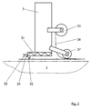
- Fig. 5 shows a side view of the mortar application device 7, which has a screw conveyor 31, the Mortar forcibly promotes an opening 32.
- the opening 32 is closed with a slide device 33, which in this case four arranged side by side Has slide 34.
- the Slider 34 By opening one or more of the Slider 34, e.g. by pneumatic, not shown or hydraulic cylinder can be reached the mortar is applied to the top layer of the masonry wall 1.
- mortar arrives in a different Width from the opening 32, allowing adaptation to different Widths of the masonry wall 1 take place can.
- the mortar application device 7 a roll 35, on which reinforcement fabric known per se 36 is rolled up.
- the reinforcing fabric 36 is in If necessary, e.g. computer controlled, unrolled from roll 35 and also on the mortar applicator 7 attached pressure rollers 37 in the top Mortar layer pressed in. Through this impression comes the reinforcement fabric 36 in the middle of the mortar layer lie and can absorb tensile stresses occurring there.
- the described device is e.g. in a factory hall: be on the floor of the hall at a predetermined distance, the rails 13 for the Wall device 2 and the extension device 22 mounted. At an appropriate distance from the rails 13 and in the same grid dimension is the base 3 for the masonry walls 1 attached to the floor. Then be nor the rails 15 and 24 orthogonal to the rails 13 relocated.
Landscapes
- Engineering & Computer Science (AREA)
- Architecture (AREA)
- Mechanical Engineering (AREA)
- Structural Engineering (AREA)
- Civil Engineering (AREA)
- Chemical & Material Sciences (AREA)
- Ceramic Engineering (AREA)
- Conveying And Assembling Of Building Elements In Situ (AREA)
- Retaining Walls (AREA)
- Processing Of Stones Or Stones Resemblance Materials (AREA)
Applications Claiming Priority (2)
| Application Number | Priority Date | Filing Date | Title |
|---|---|---|---|
| DE19813583A DE19813583B4 (de) | 1998-03-27 | 1998-03-27 | Vorrichtung zur Herstellung von Mauerwerk |
| DE19813583 | 1998-03-27 |
Publications (2)
| Publication Number | Publication Date |
|---|---|
| EP0945239A2 true EP0945239A2 (fr) | 1999-09-29 |
| EP0945239A3 EP0945239A3 (fr) | 2002-05-22 |
Family
ID=7862566
Family Applications (1)
| Application Number | Title | Priority Date | Filing Date |
|---|---|---|---|
| EP99105929A Withdrawn EP0945239A3 (fr) | 1998-03-27 | 1999-03-24 | Procédé et installation pour la fabrication de murs |
Country Status (2)
| Country | Link |
|---|---|
| EP (1) | EP0945239A3 (fr) |
| DE (1) | DE19813583B4 (fr) |
Cited By (3)
| Publication number | Priority date | Publication date | Assignee | Title |
|---|---|---|---|---|
| EP2159340A2 (fr) | 2008-08-27 | 2010-03-03 | Udo Nagl | Unité préfabriquée de briques |
| EP1918478A3 (fr) * | 2006-10-24 | 2013-11-20 | Josef Kurz | Dispositif de fabrication d'éléments préfabriqués maçonnés à partir de blocs de construction |
| CN108972866A (zh) * | 2018-08-22 | 2018-12-11 | 南京航空航天大学 | 一种自保温砌体墙片自动化生产装置 |
Families Citing this family (1)
| Publication number | Priority date | Publication date | Assignee | Title |
|---|---|---|---|---|
| DE102024124768A1 (de) | 2024-08-29 | 2026-03-05 | Rimatem GmbH | Vorrichtung zum Auftragen von Mörtel auf eine Reihe von Mauersteinen |
Family Cites Families (7)
| Publication number | Priority date | Publication date | Assignee | Title |
|---|---|---|---|---|
| DE1000145B (de) * | 1952-01-19 | 1957-01-03 | Friedrich Karl Lueder | Verfahren und Geraet zur Herstellung von Bauteilen, z.B. Waenden, insbesondere aus Formsteinen mit Trennfugen und lotrecht durchlaufenden Hohlraeumen |
| SE334729B (fr) * | 1970-01-14 | 1971-05-03 | Ytong Ab | |
| DE2530973A1 (de) * | 1975-07-11 | 1977-01-27 | Wolfgang Lachnit | Maschine zur maschinellen herstellung von bausteinmauerwerk |
| DE2646591C3 (de) * | 1976-10-15 | 1981-01-08 | Hermann Dipl.-Volksw. 4440 Rheine Twiehaus | Vo !-richtung zum Herstellen von Wandelementen aus Kunststeinen |
| DE2829863C2 (de) * | 1978-07-07 | 1982-04-15 | Ernst Riffel | Vorrichtung zum Herstellen von senkrecht stehenden Wandtafeln aus Mauersteinen |
| DE9218809U1 (de) * | 1991-01-18 | 1995-09-14 | Harmony Holdings Ltd., Vaduz | Vorrichtung zum Herstellen von Mauerstücken oder Wandtafeln aus Mauersteinen |
| DE19603234C2 (de) * | 1996-01-30 | 2001-01-04 | Paul Wasmer | Vorrichtung zm automatischen Mauern |
-
1998
- 1998-03-27 DE DE19813583A patent/DE19813583B4/de not_active Expired - Lifetime
-
1999
- 1999-03-24 EP EP99105929A patent/EP0945239A3/fr not_active Withdrawn
Cited By (5)
| Publication number | Priority date | Publication date | Assignee | Title |
|---|---|---|---|---|
| EP1918478A3 (fr) * | 2006-10-24 | 2013-11-20 | Josef Kurz | Dispositif de fabrication d'éléments préfabriqués maçonnés à partir de blocs de construction |
| EP2159340A2 (fr) | 2008-08-27 | 2010-03-03 | Udo Nagl | Unité préfabriquée de briques |
| DE102008039919A1 (de) | 2008-08-27 | 2010-03-04 | Udo Nagl | Vorgefertigte Ziegeleinheit |
| CN108972866A (zh) * | 2018-08-22 | 2018-12-11 | 南京航空航天大学 | 一种自保温砌体墙片自动化生产装置 |
| CN108972866B (zh) * | 2018-08-22 | 2023-10-17 | 南京航空航天大学 | 一种自保温砌体墙片自动化生产装置 |
Also Published As
| Publication number | Publication date |
|---|---|
| EP0945239A3 (fr) | 2002-05-22 |
| DE19813583A1 (de) | 1999-09-30 |
| DE19813583B4 (de) | 2010-05-06 |
Similar Documents
| Publication | Publication Date | Title |
|---|---|---|
| DE2910432C2 (fr) | ||
| DE102015209157B4 (de) | Schalungseinrichtung und Batterieschalung mit dieser Schalungseinrichtung | |
| AT247768B (de) | Verfahren und Vorrichtung zur Herstellung vorgefertigter, vorzugsweise stockwerkshoher Mauersteintafeln | |
| DE2918652C2 (de) | Vorrichtung zum Herstellen von monolithischen Stahlbetonraumzellen, z.B. von Fertiggaragen | |
| EP0077070B1 (fr) | Procédé et dispositif pour poser les éléments de socle nivelés d'un fond double | |
| DE19813583B4 (de) | Vorrichtung zur Herstellung von Mauerwerk | |
| AT253200B (de) | Verfahren und Vorrichtung zur Herstellung von Mauerwerk aus Bausteinen | |
| DE2649221A1 (de) | Bank zur herstellung von in einer form geformten bauelementen | |
| DE102021100228A1 (de) | Vorrichtung und Verfahren zur Herstellung einer festen, tragfähigen Konstruktion aus einem aushärtenden Baustoff sowie Aussparungsschalungssystem, Bewehrungsmatte und Befestigungselement | |
| DE2325218B2 (de) | Verfahren für den Umlauf von Paletten bei der Fertigung von Großtafeln aus armiertem Beton und Anlage zur Durchführung des Verfahrens | |
| DE3540962C2 (fr) | ||
| DE202004012919U1 (de) | Mörtelauftragsvorrichtung für Dünnbettmörtel | |
| DE1584637C3 (de) | Vorrichtung zum Herstellen einer großformatigen Bauplatte und Verwendung der Vorrichtung | |
| EP0085366B1 (fr) | Procédé et dispositif pour fabriquer des cellules tridimensionnelles en matériau de construction solidifiable | |
| DE4028884C2 (de) | Vorrichtung und Verfahren zum Herstellen von senkrecht stehenden Wandelementen aus Mauersteinen | |
| DE69411601T2 (de) | Verfahren zum Errichten von Gebäuden und dabei verwendete Vorrichtung | |
| EP0536600B1 (fr) | Dispositif pour la fabrication d'armatures | |
| AT263597B (de) | Verfahren und Vorrichtung zur Herstellung großer Bauteile | |
| AT409395B (de) | Verfahren zur herstellung mehrschaliger mauerscheiben | |
| DE1683943C3 (fr) | ||
| DE1683884C (de) | Zuteilvorrichtung fur Zuschlagstoffe zum Anschluß an Betonmischer | |
| DE1010437B (de) | Verfahren und Anlage zum Herstellen von laenglichen Erzeugnissen aus Beton oder von Reihen solcher Erzeugnisse mit einer Armierung | |
| DE3308322C2 (de) | Maschine zur Herstellung von Deckenelementen und Stürzen aus Ziegeln und Beton | |
| DE803941C (de) | Verfahren zur schalungslosen Erstellung von Stahlbeton- oder Holz-Skelettbauten | |
| DE6605645U (de) | Schalung zum herstellen von beton- und stahlbetonbauteilen mit rundem querschnitt |
Legal Events
| Date | Code | Title | Description |
|---|---|---|---|
| PUAI | Public reference made under article 153(3) epc to a published international application that has entered the european phase |
Free format text: ORIGINAL CODE: 0009012 |
|
| AK | Designated contracting states |
Kind code of ref document: A2 Designated state(s): AT BE CH CY DE DK ES FI FR GB GR IE IT LI LU MC NL PT SE |
|
| AX | Request for extension of the european patent |
Free format text: AL;LT;LV;MK;RO;SI |
|
| PUAL | Search report despatched |
Free format text: ORIGINAL CODE: 0009013 |
|
| AX | Request for extension of the european patent |
Free format text: AL;LT;LV;MK;RO;SI |
|
| AKX | Designation fees paid | ||
| REG | Reference to a national code |
Ref country code: DE Ref legal event code: 8566 |
|
| STAA | Information on the status of an ep patent application or granted ep patent |
Free format text: STATUS: THE APPLICATION IS DEEMED TO BE WITHDRAWN |
|
| 18D | Application deemed to be withdrawn |
Effective date: 20021122 |