EP0945286A1 - Schwinghebelaufhängung für ein Doppelachsfahrzeug, mit einem zentralen elastischen Element, welches mit dem Fahrzeugrahmen verbunden ist. - Google Patents
Schwinghebelaufhängung für ein Doppelachsfahrzeug, mit einem zentralen elastischen Element, welches mit dem Fahrzeugrahmen verbunden ist. Download PDFInfo
- Publication number
- EP0945286A1 EP0945286A1 EP98119657A EP98119657A EP0945286A1 EP 0945286 A1 EP0945286 A1 EP 0945286A1 EP 98119657 A EP98119657 A EP 98119657A EP 98119657 A EP98119657 A EP 98119657A EP 0945286 A1 EP0945286 A1 EP 0945286A1
- Authority
- EP
- European Patent Office
- Prior art keywords
- suspension system
- axles
- rocker arm
- vehicle
- cylinder
- Prior art date
- Legal status (The legal status is an assumption and is not a legal conclusion. Google has not performed a legal analysis and makes no representation as to the accuracy of the status listed.)
- Withdrawn
Links
- 239000000725 suspension Substances 0.000 title claims abstract description 27
- 239000012530 fluid Substances 0.000 claims description 9
- 239000000463 material Substances 0.000 claims description 3
- 230000000284 resting effect Effects 0.000 claims 1
- 230000010355 oscillation Effects 0.000 description 4
- 239000006096 absorbing agent Substances 0.000 description 2
- 238000010276 construction Methods 0.000 description 2
- 238000006073 displacement reaction Methods 0.000 description 2
- 239000007788 liquid Substances 0.000 description 2
- 239000002184 metal Substances 0.000 description 2
- 230000035939 shock Effects 0.000 description 2
- 230000006835 compression Effects 0.000 description 1
- 238000007906 compression Methods 0.000 description 1
- 238000013016 damping Methods 0.000 description 1
- 230000001419 dependent effect Effects 0.000 description 1
- 230000000694 effects Effects 0.000 description 1
- 229920001971 elastomer Polymers 0.000 description 1
- 230000004048 modification Effects 0.000 description 1
- 238000012986 modification Methods 0.000 description 1
- 229920000642 polymer Polymers 0.000 description 1
- 239000005060 rubber Substances 0.000 description 1
- 238000007789 sealing Methods 0.000 description 1
- 239000007787 solid Substances 0.000 description 1
Images

Classifications
-
- B—PERFORMING OPERATIONS; TRANSPORTING
- B60—VEHICLES IN GENERAL
- B60G—VEHICLE SUSPENSION ARRANGEMENTS
- B60G5/00—Resilient suspensions for a set of tandem wheels or axles having interrelated movements
- B60G5/02—Resilient suspensions for a set of tandem wheels or axles having interrelated movements mounted on a single pivoted arm, e.g. the arm being rigid
-
- B—PERFORMING OPERATIONS; TRANSPORTING
- B60—VEHICLES IN GENERAL
- B60G—VEHICLE SUSPENSION ARRANGEMENTS
- B60G11/00—Resilient suspensions characterised by arrangement, location or kind of springs
- B60G11/14—Resilient suspensions characterised by arrangement, location or kind of springs having helical, spiral or coil springs only
- B60G11/16—Resilient suspensions characterised by arrangement, location or kind of springs having helical, spiral or coil springs only characterised by means specially adapted for attaching the spring to axle or sprung part of the vehicle
-
- B—PERFORMING OPERATIONS; TRANSPORTING
- B60—VEHICLES IN GENERAL
- B60G—VEHICLE SUSPENSION ARRANGEMENTS
- B60G2200/00—Indexing codes relating to suspension types
- B60G2200/30—Rigid axle suspensions
- B60G2200/318—Rigid axle suspensions two or more axles being mounted on a longitudinal rocking or walking beam
-
- B—PERFORMING OPERATIONS; TRANSPORTING
- B60—VEHICLES IN GENERAL
- B60G—VEHICLE SUSPENSION ARRANGEMENTS
- B60G2204/00—Indexing codes related to suspensions per se or to auxiliary parts
- B60G2204/10—Mounting of suspension elements
- B60G2204/12—Mounting of springs or dampers
- B60G2204/124—Mounting of coil springs
Definitions
- the present invention relates to a rocker arm suspension for a tandem axle vehicle provided with a central elastic member connected to the vehicle frame.
- An articulated structure of this kind is rigidly connected to the vehicle frame or self-bearing structure through a central articulated joint allowing the swinging of the two axles along a vertical direction (upwards or downwards) so that the wheels can move over humps and bumps by rotating about such joint while at the same time transferring to the frame the vibrations caused by the road unevenness
- the arms are usually made up by leaf springs.
- the known axles suspension systems have a poor drive comfort caused by an insufficient cushioning of the road irregularities, because of the use of a too rigid elastic means.
- An uneven road surface causes vibrations and stresses that are harmful to the whole vehicle structure, and moreover cause a loss of adherence between the tires and the ground, thus increasing the tire wear with a reduction of their useful life.
- the known devices have not yet satisfactorily solved the technical problem of cushioning the oscillations caused by the road unevenness that are transmitted to the vehicle frame.
- EP-A-0 149 262 in the name of the present applicant, discloses a suspension system provided with rigid arms having an end directly connected to the axles and being articulated at their centre at a pivot pin about which the system can rotate, which arms act onto an elastic body whose deformation - caused by the oscillation of the arms about their pivot pin - accomplishes the suspension effect.
- an elastic member formed by a pair of parts movable relative to one another is disposed between the vehicle frame and the tandem point of connection, one of such parts being directly anchored to the frame, and with at least one elastic means located between said pair of parts and being compressed by their relative displacement along a given direction.
- the two parts or members movable relative to one another are realized by means of a circular cross-section cylinder and a slidable member or piston movable within such cylinder along an upwards-downwards direction.
- a cylinder-piston assembly By using a cylinder-piston assembly the side pushes and the sideways thrusts applied by the axles are kept low.
- an elastic or resilient means acting as an air cushion or shock absorber to damp the vertical oscillations generated by an uneven road and transmitted to the vehicle frame.
- This elastic means can comprise a fluid, preferably a gaseous fluid, for example air, or a liquid, for example oil, or even elastic metal components such as a metal spring, or polymer elastic bodies, for example rubbers.
- a fluid preferably a gaseous fluid, for example air, or a liquid, for example oil, or even elastic metal components such as a metal spring, or polymer elastic bodies, for example rubbers.
- a compressible fluid for example air
- Another possible embodiment employs an oil (incompressible per se) in which there are dispersed or otherwise contained bubbles of a gas, such as air, such bubbles being compressed when the two movable parts, in particular the piston and/or the cylinder, axially move/s towards a closing position.
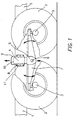
- a portion of a vehicle provided with several axles for the transport of goods, for example a truck and full trailer, comprising a chassis frame with only two portions of the side members 1 being represented, and at least two adjacent axles 3, 3 to each ends of which wheels (or pairs of wheels) 2, 2 are mounted.
- the suspension member 4 secured to the frame by means of a flanged portion 11 and bolts 8.
- the suspension member 4 is formed by two coaxial cylinders, respectively an outer fixed cylinder 9 secured to the frame, and an inner cylinder 10 movable along a vertical direction.
- At least one elastic or resilient compressible means acting as a shock absorber is provided within the cylinder 10, for example a resilient solid body, such as a helical spring or a body of a polymeric material, or a fluid elastic body, such as a liquid or a gas, or a combination of two or more of such elastic means.
- a resilient solid body such as a helical spring or a body of a polymeric material
- a fluid elastic body such as a liquid or a gas, or a combination of two or more of such elastic means.
- a combination formed by two or more elastic means for example a helical spring and a compressible fluid (for example air), so as to obtain an optimum resulting elastic characteristic of the assembly.
- a compressible fluid for example air
- Another possible embodiment of the invention provides for the use of an oil (that it by itself incompressible) into which are dispersed or anyhow present bubbles of a gas, such as air, that are compressed when the two movable parts, in particular the piston and/or the cylinder, axially move/s towards a closing position.
- the suspension member allows a vertical displacement of the whole assembly, while the compression of the fluid (for example air or a gas) and/or of the spring accomplishes the desired suspension function.
- the movable cylinder 10 carries at the lower end a fork 5 to which an articulation pin 6 of a rocker arm 7 is mounted.
- the ends of this rocker arm rest on the adjacent axles 3 of the vehicle wheels 2, and the pin 6 allows the rocker 7 to oscillate about its axis (i.e. the axis of pin 6).
- the rocker arm 7 is formed as a rigid body, although this embodiment is not to be construed as a limitation since the rocker arm can be provided with a certain amount of elasticity, for example by realizing the rocker with a spring leaf or the like.
- an articulated connection or joint between the movable member 10 (the piston in the present case) and the axles 3 there is provided an articulated connection or joint.
- Such articulated connection can be built in several forms, e.g. as a ball joint.
Landscapes
- Engineering & Computer Science (AREA)
- Mechanical Engineering (AREA)
- Vehicle Body Suspensions (AREA)
- Springs (AREA)
Applications Claiming Priority (2)
| Application Number | Priority Date | Filing Date | Title |
|---|---|---|---|
| ITTO980251 | 1998-03-24 | ||
| ITTO980251 ITTO980251A1 (it) | 1998-03-24 | 1998-03-24 | Sospensione a bilanciere per assi tandem con elemento elastico central e collegato al telaio. |
Publications (1)
| Publication Number | Publication Date |
|---|---|
| EP0945286A1 true EP0945286A1 (de) | 1999-09-29 |
Family
ID=11416626
Family Applications (1)
| Application Number | Title | Priority Date | Filing Date |
|---|---|---|---|
| EP98119657A Withdrawn EP0945286A1 (de) | 1998-03-24 | 1998-10-17 | Schwinghebelaufhängung für ein Doppelachsfahrzeug, mit einem zentralen elastischen Element, welches mit dem Fahrzeugrahmen verbunden ist. |
Country Status (2)
| Country | Link |
|---|---|
| EP (1) | EP0945286A1 (de) |
| IT (1) | ITTO980251A1 (de) |
Cited By (2)
| Publication number | Priority date | Publication date | Assignee | Title |
|---|---|---|---|---|
| CN111038203A (zh) * | 2020-03-17 | 2020-04-21 | 绩溪县徽洋车桥有限责任公司 | 一种电动汽车车桥 |
| AT525736A4 (de) * | 2022-05-09 | 2023-07-15 | Anton Johann Gottfried | Fahrgestell für ein Kraftfahrzeug |
Citations (3)
| Publication number | Priority date | Publication date | Assignee | Title |
|---|---|---|---|---|
| US2493004A (en) * | 1945-08-27 | 1950-01-03 | Robert W Pointer | Vehicle suspension |
| FR1252924A (fr) * | 1959-12-21 | 1966-06-03 | Perfectionnements aux suspensions progressives pour véhicules | |
| US4360220A (en) * | 1980-07-14 | 1982-11-23 | Beers Lionel W | Independent, load-seeking, preloaded, vehicle suspension |
-
1998
- 1998-03-24 IT ITTO980251 patent/ITTO980251A1/it unknown
- 1998-10-17 EP EP98119657A patent/EP0945286A1/de not_active Withdrawn
Patent Citations (3)
| Publication number | Priority date | Publication date | Assignee | Title |
|---|---|---|---|---|
| US2493004A (en) * | 1945-08-27 | 1950-01-03 | Robert W Pointer | Vehicle suspension |
| FR1252924A (fr) * | 1959-12-21 | 1966-06-03 | Perfectionnements aux suspensions progressives pour véhicules | |
| US4360220A (en) * | 1980-07-14 | 1982-11-23 | Beers Lionel W | Independent, load-seeking, preloaded, vehicle suspension |
Cited By (5)
| Publication number | Priority date | Publication date | Assignee | Title |
|---|---|---|---|---|
| CN111038203A (zh) * | 2020-03-17 | 2020-04-21 | 绩溪县徽洋车桥有限责任公司 | 一种电动汽车车桥 |
| CN111038203B (zh) * | 2020-03-17 | 2022-11-22 | 绩溪县徽洋车桥有限责任公司 | 一种电动汽车车桥 |
| AT525736A4 (de) * | 2022-05-09 | 2023-07-15 | Anton Johann Gottfried | Fahrgestell für ein Kraftfahrzeug |
| AT525736B1 (de) * | 2022-05-09 | 2023-07-15 | Anton Johann Gottfried | Fahrgestell für ein Kraftfahrzeug |
| EP4275928A1 (de) | 2022-05-09 | 2023-11-15 | Rehberger, Ingrid | Fahrgestell für ein kraftfahrzeug |
Also Published As
| Publication number | Publication date |
|---|---|
| ITTO980251A1 (it) | 1999-09-24 |
Similar Documents
| Publication | Publication Date | Title |
|---|---|---|
| US5785345A (en) | Means for and method of controlling frame rise in vehicle suspensions | |
| US5366237A (en) | Axle suspension systems | |
| AU707479B2 (en) | Beam-type axle suspension system | |
| AU703205B2 (en) | Linkage suspension system | |
| CA2467792C (en) | Spacer for suspension arm bushing assemblies | |
| AU2002360652A1 (en) | Spacer for suspension arm bushing assemblies | |
| CA1193294A (en) | Vehicle axle suspension | |
| CA1236139A (en) | Dual trailing arm vehicle suspension system | |
| US2816616A (en) | Vehicle wheel suspension | |
| US3726540A (en) | Tandem axle suspension system for heavy-duty vehicle | |
| EP1309461A1 (de) | Radaufhängungsanordnung | |
| US3751063A (en) | Multiple joint tandem suspension with torque springs | |
| KR100579227B1 (ko) | 자동차의 후륜 현가장치 | |
| CA1195359A (en) | Suspension for pivotally mounting a rigid axle assembly | |
| CN85104432A (zh) | 具有不同弹性元件的机动车辆悬架 | |
| CZ2024498A3 (cs) | Zařízení pro odpružení těžkých náprav | |
| GB2099380A (en) | Improvements in or relating to vehicle suspension devices | |
| KR19980029888U (ko) | 판 스프링에 의한 자동차 어퍼 암 축핀의 핀 볼트 고정구조 | |
| NZ260280A (en) | Vehicle axle rigidly attached to swing beam by passing through beam side walls so as to minimise distortion of axle cross-section | |
| WO1997024236A1 (en) | Improvements relating to vehicle suspensions systems | |
| MXPA93006307A (en) | Axle suspension system for overhead vehicles |
Legal Events
| Date | Code | Title | Description |
|---|---|---|---|
| PUAI | Public reference made under article 153(3) epc to a published international application that has entered the european phase |
Free format text: ORIGINAL CODE: 0009012 |
|
| AK | Designated contracting states |
Kind code of ref document: A1 Designated state(s): AT BE CH CY DE DK ES FI FR GB GR IE IT LI LU MC NL PT SE |
|
| AX | Request for extension of the european patent |
Free format text: AL;LT;LV;MK;RO;SI |
|
| AKX | Designation fees paid | ||
| REG | Reference to a national code |
Ref country code: DE Ref legal event code: 8566 |
|
| STAA | Information on the status of an ep patent application or granted ep patent |
Free format text: STATUS: THE APPLICATION IS DEEMED TO BE WITHDRAWN |
|
| 18D | Application deemed to be withdrawn |
Effective date: 20000330 |