EP0945307A2 - Befestigungsvorrichtung für Lastenträger an Kraftfahrzeugen - Google Patents
Befestigungsvorrichtung für Lastenträger an Kraftfahrzeugen Download PDFInfo
- Publication number
- EP0945307A2 EP0945307A2 EP99302254A EP99302254A EP0945307A2 EP 0945307 A2 EP0945307 A2 EP 0945307A2 EP 99302254 A EP99302254 A EP 99302254A EP 99302254 A EP99302254 A EP 99302254A EP 0945307 A2 EP0945307 A2 EP 0945307A2
- Authority
- EP
- European Patent Office
- Prior art keywords
- support
- roof
- gutter
- carrying device
- fastener
- Prior art date
- Legal status (The legal status is an assumption and is not a legal conclusion. Google has not performed a legal analysis and makes no representation as to the accuracy of the status listed.)
- Withdrawn
Links
- 230000007246 mechanism Effects 0.000 title claims abstract description 37
- 238000005192 partition Methods 0.000 claims description 8
- 238000004873 anchoring Methods 0.000 claims description 7
- 230000033001 locomotion Effects 0.000 claims description 5
- 238000006073 displacement reaction Methods 0.000 claims description 3
- 230000002459 sustained effect Effects 0.000 claims description 3
- 230000003028 elevating effect Effects 0.000 claims description 2
- 230000000717 retained effect Effects 0.000 claims 3
- 230000001133 acceleration Effects 0.000 description 1
- 230000004075 alteration Effects 0.000 description 1
- 230000001681 protective effect Effects 0.000 description 1
- 239000007787 solid Substances 0.000 description 1
Images




Classifications
-
- B—PERFORMING OPERATIONS; TRANSPORTING
- B60—VEHICLES IN GENERAL
- B60R—VEHICLES, VEHICLE FITTINGS, OR VEHICLE PARTS, NOT OTHERWISE PROVIDED FOR
- B60R9/00—Supplementary fittings on vehicle exterior for carrying loads, e.g. luggage, sports gear or the like
- B60R9/04—Carriers associated with vehicle roof
- B60R9/058—Carriers associated with vehicle roof characterised by releasable attaching means between carrier and roof
Definitions
- the present invention relates to brackets and clip mechanisms for securing utility racks to various vehicles and, more particularly, to different types of gutters and anchors provided on such vehicles.
- a utility rack It is frequently necessary for owners of vehicles, such as cars, to install on the roof thereof a utility rack in order to carry on the utility rack various objects which are either too awkward or too large to be positioned within the vehicle, whereby it becomes preferable to carry these objects on the outside of the vehicle. Accordingly, many utility racks have been designed to be fastened to the vehicles with a view of carrying objects, such as skis, bicycles, sailboards, etc. Regardless of the areas of attachment to the vehicle, a carrying device such as a utility rack must meet certain criteria. For instance, the utility rack must be firmly attached to the vehicle and remain secure during all of the normal motions encountered by the vehicle, such as acceleration, deceleration, turns, and also sudden movements.
- the attachment points have to be firm and must be able to bear the weight of the intended load.
- the carrier should be easy to attach to and remove from the vehicle. If the carrying device is basically permanently mounted to the vehicle, the vehicle should not require any alteration whatsoever and should retain its original appearance if the carrying device is removed therefrom.
- a bracket for removably attaching an object carrying device to a vehicle of type having a pair of opposed supports and a carrier bar extending therebetween wherein at least one of the supports is capable of displacement along the carrier bar, said bracket being provided at each support, comprising a lower hook portion adapted to engage a protrusion of the roof of the vehicle, and an upper load bearing portion adapted to be fastened to the support and against an inside face thereof, such that once said hook portions of two brackets have been positioned outwardly of respective protrusions of the roof, at least once support is displaced inwardly such that said brackets engage the protrusions and thus secure the supports and the object carrying device to the roof, wherein outward anchoring stresses applied on said brackets are sustained by substantially the whole supports.
- a clip mechanism for removably attaching an object carrying device to a roof gutter of a vehicle of type having a pair of opposed supports and a carrier bar extending therebetween, the gutter having therein an upwardly protruding anchor having opposed protruding ends, comprising a clip means having a pair of displaceable jaws and a web portion therebetween, a threaded member at said web portion, a bolt engaged in said threaded member, said bolt being mounted in the support, wherein rotation of said bolt causes said threaded to elevate thereby pulling on said web portion and forcing said jaws inwardly into engagement with the protruding ends of the gutter's anchor and thus securing the object carrying device to the roof.
- a clip mechanism for removably attaching an object carrying device to a roof gutter of a vehicle of type having a pair of opposed supports and a carrier bar extending therebetween, the gutter defining inwardly projecting upper lips, comprising a inverted U-shaped member having a pair of side arms defining lower hook portions, a bolt mounted in the support and extending through said U-shaped member, a spreading member located between said side arms and threadably engaging said bolt, wherein when said bolt is rotated said spreading member is forced to elevate thereby spreading said side arms such that said hook portion engage the lips of the gutter and thus securing the object carrying device to the roof.
- FIG. 1 illustrates part of a utility rack R provided at the opposed ends thereof with a pair of feet or supports 10, only one such support 10 being shown in Fig. 1.
- the utility rack R also includes a bridge or carrier bar 12 which joins both supports 10.
- Each support 10 includes a high friction resilient and protective sole 14 for overlying a roof 16 (only partly shown in Fig. 1) of a vehicle which is not shown herein.
- the roof defines in Fig. 1 a gutter 18 with the support 10 being securely anchored thereto, as explained in details hereinbelow.
- the support 10 includes a hollow housing 20, a pivotable door 22 to provide access to the inside of the housing 20, this door 22 being lockable by way of a lock mechanism 24.
- the door is adapted to pivot in a plane transversal to the roof 16 and along a longitudinal axis of the carrier bar 12, as seen by arrow 26 (see Fig. 1).
- a first bracket 28 is shown assembled to the support 10 of the utility rack R.
- the first bracket 28 includes a lower hook portion 30 adapted to engage the roof of the vehicle, an intermediate straight portion 32 defining a hole therein such that the first bracket 28 can be secured to the support 10 by way of bolt 34 and nut 36, and an upper multi-hook portion 38 which includes two end elbows (not shown) adapted to abuttingly overly a structural member 40 of the support 10 and which further includes a pair of upper hooks 42, located between the aforementioned end elbows, and adapted to be engaged in slots 44 (see Figs. 3 and 4) located above the structural member 40.
- the first bracket 28 is engaged to the support 10 by its upper hooks 42 engaging the slots 44 and with the end elbows of the bracket 28 overlying the structural member 40 of the support 10; the intermediate portion 32 bears against the inner side wall of the structural member 40 and the lower hook portion 30 is adapted to engage a rib or protrusion defined by the roof.
- At least one of the end supports 10 of the utility rack R is capable of being displaced translationally along, and relative to, the carrier bar 12 such as to vary the span between the two supports 10.
- the hook portions 30 of the brackets 28 of both supports 10 are sufficiently spaced apart such that they can be lowered and positioned outwardly of the roof's rib or protrusion which they will engage.
- bolt 46 is rotated (typically with an Allen key) along arrow 48 of Fig. 3 such as to displace the support 10 along arrow 50 respective to the carrier bar 12.
- the inward transitional displacement of the support 10 causes the hook portions of both the brackets 28 to firmly engage the roof of the vehicle thereby solidly anchoring the utility rack R thereto.
- the present first bracket 28 is disposed inwardly of the support 10 such that the load that the first bracket 28 is bearing when the rack R is secured to the roof is also being sustained by the whole support 10, whereby the present invention provides a much more solid assembly of a roof engaging bracket with an end support of a rack. With the anchor plate or first bracket 28 on the inside of the support 10, the support 10 does not deform under anchoring stress.
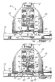
- Figs. 4 to 6 illustrate the utility rack R provided with a first clip mechanism 52 which includes a bolt 54, an upper plate 56, a threaded member 58 and a clip 60 provided with a pair of jaws 62.
- a first clip mechanism 52 which includes a bolt 54, an upper plate 56, a threaded member 58 and a clip 60 provided with a pair of jaws 62.
- Inside of the housing 20 of the support 10 there are provided a pair of horizontal structural merging walls 64 with the upper plate 56 being located above the upper one of these two walls 64 and with the bolt 54 extending through the upper plate 56 and through holes defined in the horizontal walls 64.
- the head of the bolt 54 overlies the upper plate 56.
- the bolt 54 threadably engages the threaded member 58 which has the form of a horizontal U.
- Fig. 4 shows the clip 60 in its expanded position, wherein the jaws 62 are sufficiently spaced apart so that the support 10 can be lowered onto the roof with the jaws 62 outwardly clearing a trapezoidal anvil or T-shaped anchor 68 which is permanently secured inside a gutter 70 of the roof. Then, the bolt 54 is rotated as per arrow 72 of Fig. 5 and, as the bolt 54 is restricted by the upper horizontal wall 64, the rotation thereof causes the threaded member 58 to rise (as per arrow 74) along the threaded body of the bolt 54.
- each jaw 62 includes a pair of sidewalls 78 which are joined at their lower edges by a bottom wall 80 thereby defining an opening 82 through which the T-shaped anchor 68 can extend.
- Figs. 7 and 8 illustrate a second clip mechanism 84 for use with a further gutter 86 provided in the roof 16 of the vehicle, the gutter 86 including a pair of inwardly projecting lips 88.
- the second clip mechanism 84 comprises an elongated inverted U-shaped body 90 defining an opening 92 at its apex, a bolt 94 mounted in the housing 20 of the support 10 as in the case of bolt 54 of Figs 4 to 6 in that the bolt 94 extends through an opening 96 defined in structural members 64 of the support 10, and an upper plate 98 disposed between the head of the bolt 94 and the structural members 64 of the support 10.
- An elongated threaded bar 100 is located between a pair of side arms 102 of the U-shaped body 90.
- the side arms each define at their lower ends a hook portion 104.
- the threaded bar 100 is located along the bolt 94 such that the hook portions 104 are sufficiently closed together such that the clip mechanism 84 attached to the support 10 of the utility rack R can be lowered into the gutter 86, the hook portions 104 inwardly clearly the lips 88 of the gutter 86 (see arrow 106) when forced therethrough against their resiliency with the hook portions 104 defining angled lower leading edges to facilitate the introduction of the hook portions through the lips 88 and into the gutter 86.
- the bolt 94 is rotated as per arrow 108 in Fig.
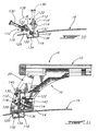
- Fig. 9 specifically shows a second bracket 112 provided with an angled intermediate section 114, an upper plate 116 integral to the angled section 114, and a hook assembly integral and provided at the lower end of the angled section 114 and comprising a pair of straight end supports 118 and an elongated central hook portion 120.
- a U-shaped threaded member 122 (similar to threaded member 58 of Figs. 4 to 6) is disposed above and below the upper plate 116.
- the threaded member 122 defines an upper opening 124 and a lower threaded hub 126 (best seen in Figs. 9 and 10) with the upper plate 116 defining an opening 128 aligned with the threaded hub 126 and the upper opening 124 of the threaded member 122.
- the second bracket 112 also includes a bolt 130 which threadably engages the threaded hub 126 of the threaded member 122.
- the second bracket 112 is adapted to secure the utility rack R to a specific gutter 132 which includes a central raised wall 134 defining a side rib 136 at an upper end thereof.
- the second bracket 112 is first positioned at an angle (see bracket 112 in solid lines in Fig. 10) such that its central hook portion 120 can engage the side rib 136 while allowing the end supports 118 to slide above the central wall 134, and then the bolt 130 is pivoted along arrow 138 until it adopts a position thereof shown in phantom lines in Fig.
Landscapes
- Engineering & Computer Science (AREA)
- Mechanical Engineering (AREA)
- Fittings On The Vehicle Exterior For Carrying Loads, And Devices For Holding Or Mounting Articles (AREA)
- Body Structure For Vehicles (AREA)
- Supports For Pipes And Cables (AREA)
Applications Claiming Priority (2)
| Application Number | Priority Date | Filing Date | Title |
|---|---|---|---|
| CA002232829A CA2232829A1 (en) | 1998-03-23 | 1998-03-23 | Attachment mechanisms for securing utility racks to vehicles |
| CA2232829 | 1998-03-23 |
Publications (2)
| Publication Number | Publication Date |
|---|---|
| EP0945307A2 true EP0945307A2 (de) | 1999-09-29 |
| EP0945307A3 EP0945307A3 (de) | 2000-04-05 |
Family
ID=4162239
Family Applications (1)
| Application Number | Title | Priority Date | Filing Date |
|---|---|---|---|
| EP99302254A Withdrawn EP0945307A3 (de) | 1998-03-23 | 1999-03-23 | Befestigungsvorrichtung für Lastenträger an Kraftfahrzeugen |
Country Status (5)
| Country | Link |
|---|---|
| US (1) | US6182876B1 (de) |
| EP (1) | EP0945307A3 (de) |
| JP (1) | JP2000118310A (de) |
| BR (1) | BR9915372A (de) |
| CA (1) | CA2232829A1 (de) |
Cited By (16)
| Publication number | Priority date | Publication date | Assignee | Title |
|---|---|---|---|---|
| EP1136323A1 (de) * | 2000-03-24 | 2001-09-26 | Scambia Industrial Developments Aktiengesellschaft | Lastenträger für ein Kraftfahrzeug sowie Kraftfahrzeug mit einem Lastenträger |
| EP1088704A3 (de) * | 1999-09-30 | 2003-09-10 | Meritor Automotive GmbH | Vorrichtung zur lösbaren Befestigung eines Lastenträgers an einem Fahrzeug |
| DE10234572A1 (de) * | 2002-07-30 | 2004-02-26 | Webasto Vehicle Systems International Gmbh | Befestigungsvorrichtung für einen Dachgepäckträger |
| EP1205357A3 (de) * | 2000-10-24 | 2004-08-04 | Van den Born, Marcus Philippus Adrianus | Dachlastenträger bestehend aus Modulteilen |
| WO2004094194A1 (en) * | 2003-04-16 | 2004-11-04 | Sportrack, Llc | Securement mechanism includng top loading tie down cleat assembly and locking member |
| EP1820697A1 (de) * | 2006-02-20 | 2007-08-22 | Aurilis Group Italia S.R.L. | Vorrichtung zur Befestigung Mehrzweck-Querstangen für Fahrzeuge |
| US7497651B2 (en) | 2003-04-16 | 2009-03-03 | Sportrack Llc | Securement mechanism |
| EP2200868A4 (de) * | 2007-09-24 | 2012-12-19 | Hubco Automotive Ltd | Universalfuss für einen dachträger |
| EP2783919A1 (de) * | 2013-03-25 | 2014-10-01 | Kamei GmbH & Co. KG. | Vorrichtung zum Befestigen einer Dachbox |
| US8925775B2 (en) | 2012-07-30 | 2015-01-06 | Yakima Innovation Development Corporation | Crossbar T-slot infill |
| US9102274B2 (en) | 2007-09-21 | 2015-08-11 | Hubco Automotive Limited | Resilient infill |
| US9132782B2 (en) | 2008-09-15 | 2015-09-15 | Hubco Automotive Limited | Bracket and a crossbar assembly for a roof rack |
| US9187047B2 (en) | 2012-04-30 | 2015-11-17 | Yakima Products, Inc. | Retention dock |
| US9409527B2 (en) | 2007-09-21 | 2016-08-09 | Hubco Automotive Limited | Extendable roof rack |
| US10040403B2 (en) | 2015-06-09 | 2018-08-07 | Yakima Products, Inc. | Crossbar clamp actuator |
| CN111216646A (zh) * | 2020-03-17 | 2020-06-02 | 蒙城县望槐信息科技有限责任公司 | 一种便于安装的汽车行李架 |
Families Citing this family (14)
| Publication number | Priority date | Publication date | Assignee | Title |
|---|---|---|---|---|
| US6311882B1 (en) * | 2000-05-09 | 2001-11-06 | Jac Products, Inc. | Adaptor for mounting a slat over a roof ditch in a vehicle roof |
| US6409063B1 (en) * | 2000-10-20 | 2002-06-25 | Jac Products, Inc. | Vehicle article carrier having angled tap plate and cooperating slat |
| SE0203734L (sv) * | 2002-12-18 | 2004-06-08 | Thule Sweden Ab | Lastbärarfot |
| US20040155233A1 (en) * | 2003-02-06 | 2004-08-12 | Clift Kenneth L. | Small craft hand rail assembly |
| US20070235485A1 (en) * | 2006-03-28 | 2007-10-11 | Ford Global Technologies, Llc | System for mounting an automotive accessory |
| USD582337S1 (en) * | 2006-11-01 | 2008-12-09 | Tracrac, Inc. | Set of overhead racks |
| US20150232038A1 (en) * | 2012-08-14 | 2015-08-20 | Hubco Automotive Limited | Roof rack leg for a roof rail |
| US9643542B2 (en) | 2013-12-20 | 2017-05-09 | Jac Products, Inc. | Vehicle article carrier system having cross bar end supports with anti-loosening mechanism |
| EP3552881B1 (de) * | 2018-04-11 | 2020-07-08 | Thule Sweden AB | Lastenträger |
| USD885304S1 (en) * | 2018-06-15 | 2020-05-26 | Thule Sweden Ab | Rack foot |
| EP3594065B1 (de) * | 2018-07-13 | 2020-11-04 | Thule Sweden AB | Lastenträger |
| US11433800B2 (en) * | 2019-12-20 | 2022-09-06 | Jac Products, Inc. | Article carrier track system |
| US11752945B2 (en) * | 2020-02-06 | 2023-09-12 | Honda Motor Co., Ltd. | Roof rack system for a vehicle |
| US20250121891A1 (en) * | 2023-10-16 | 2025-04-17 | Ford Global Technologies, Llc | Cross bar attachment interface to base plate |
Family Cites Families (18)
| Publication number | Priority date | Publication date | Assignee | Title |
|---|---|---|---|---|
| FR1211727A (fr) * | 1958-10-04 | 1960-03-17 | Accessoire pour le transport d'objets sur le toit des automobiles | |
| US3917136A (en) * | 1974-05-08 | 1975-11-04 | Miles Thomas Carson | Vehicle rack mounting means |
| DE3201171A1 (de) | 1982-01-16 | 1983-07-28 | Oris-Metallbau KG Hans Riehle, 7141 Möglingen | "befestigung von gepaeckbuegeln, relingen o.dgl. auf einem kraftwagendach" |
| SE454156B (sv) | 1985-06-13 | 1988-04-11 | Kalix Mekaniska Ind | Lastberare |
| DE3614740A1 (de) * | 1986-04-30 | 1987-11-05 | Bayerische Motoren Werke Ag | Gepaecktraegerbefestigung an einem fahrzeugdach |
| SE455589B (sv) | 1987-01-12 | 1988-07-25 | Thule Ind Ab | Festanordning for en for ett fordonstak avsedd lastanordning |
| DE3729641A1 (de) | 1987-09-04 | 1989-03-23 | Opel Adam Ag | Dachlasttraeger fuer ein kraftfahrzeug |
| SE459569B (sv) * | 1987-11-24 | 1989-07-17 | Thule Ind Ab | Anordning foer uppbaerning av en last |
| DE4007263A1 (de) | 1989-03-15 | 1990-09-20 | Volkswagen Ag | Anordnung zur loesbaren befestigung eines gepaecktraegers auf einem fahrzeugdach |
| DE4027452A1 (de) | 1990-08-30 | 1992-03-05 | Opel Adam Ag | Dachlasttraeger |
| DE4108058C2 (de) * | 1991-03-13 | 1995-01-12 | Votex Gmbh | Dachgepäckträger für Kraftfahrzeuge mit Dachreling |
| FR2675444B1 (fr) * | 1991-04-18 | 1993-09-03 | Crometal | Ensemble de porte-charge, tel que porte-skis pour voitures. |
| SE470015B (sv) * | 1991-11-13 | 1993-10-25 | Thule Ind Ab | Lastbärarfot |
| SE501766C2 (sv) * | 1992-06-24 | 1995-05-08 | Thule Ind Ab | Lastbärarfot |
| JPH06107077A (ja) * | 1992-09-30 | 1994-04-19 | Honda Access:Kk | 自動車用ルーフキャリア |
| DE4313885A1 (de) * | 1993-04-28 | 1994-11-03 | Happich Gmbh Gebr | Dachlastenträger für Fahrzeuge |
| SE504203C2 (sv) | 1995-04-04 | 1996-12-09 | Mont Blanc Ind Ab | Anordning för lösbar infästning av objekt på ett underlag |
| GB2314059B (en) | 1996-06-12 | 2000-09-06 | Jac Products Inc | Load bar for automobile luggage carrier |
-
1998
- 1998-03-23 CA CA002232829A patent/CA2232829A1/en not_active Abandoned
-
1999
- 1999-03-23 BR BR9915372-6A patent/BR9915372A/pt not_active Application Discontinuation
- 1999-03-23 US US09/274,589 patent/US6182876B1/en not_active Expired - Lifetime
- 1999-03-23 EP EP99302254A patent/EP0945307A3/de not_active Withdrawn
- 1999-03-23 JP JP11078136A patent/JP2000118310A/ja active Pending
Non-Patent Citations (1)
| Title |
|---|
| None |
Cited By (25)
| Publication number | Priority date | Publication date | Assignee | Title |
|---|---|---|---|---|
| EP1088704A3 (de) * | 1999-09-30 | 2003-09-10 | Meritor Automotive GmbH | Vorrichtung zur lösbaren Befestigung eines Lastenträgers an einem Fahrzeug |
| EP1136323A1 (de) * | 2000-03-24 | 2001-09-26 | Scambia Industrial Developments Aktiengesellschaft | Lastenträger für ein Kraftfahrzeug sowie Kraftfahrzeug mit einem Lastenträger |
| EP1205357A3 (de) * | 2000-10-24 | 2004-08-04 | Van den Born, Marcus Philippus Adrianus | Dachlastenträger bestehend aus Modulteilen |
| DE10234572A1 (de) * | 2002-07-30 | 2004-02-26 | Webasto Vehicle Systems International Gmbh | Befestigungsvorrichtung für einen Dachgepäckträger |
| DE10234572B4 (de) * | 2002-07-30 | 2006-03-02 | Webasto Ag | Befestigungsvorrichtung für einen Dachgepäckträger |
| WO2004094194A1 (en) * | 2003-04-16 | 2004-11-04 | Sportrack, Llc | Securement mechanism includng top loading tie down cleat assembly and locking member |
| US7040849B2 (en) | 2003-04-16 | 2006-05-09 | Sportrack Llc | Securement mechanism including top loading tie down cleat assembly and locking member |
| US7497651B2 (en) | 2003-04-16 | 2009-03-03 | Sportrack Llc | Securement mechanism |
| EP1820697A1 (de) * | 2006-02-20 | 2007-08-22 | Aurilis Group Italia S.R.L. | Vorrichtung zur Befestigung Mehrzweck-Querstangen für Fahrzeuge |
| US9102274B2 (en) | 2007-09-21 | 2015-08-11 | Hubco Automotive Limited | Resilient infill |
| US9409527B2 (en) | 2007-09-21 | 2016-08-09 | Hubco Automotive Limited | Extendable roof rack |
| EP2200868A4 (de) * | 2007-09-24 | 2012-12-19 | Hubco Automotive Ltd | Universalfuss für einen dachträger |
| US9132782B2 (en) | 2008-09-15 | 2015-09-15 | Hubco Automotive Limited | Bracket and a crossbar assembly for a roof rack |
| US9187047B2 (en) | 2012-04-30 | 2015-11-17 | Yakima Products, Inc. | Retention dock |
| US8925775B2 (en) | 2012-07-30 | 2015-01-06 | Yakima Innovation Development Corporation | Crossbar T-slot infill |
| EP2783919A1 (de) * | 2013-03-25 | 2014-10-01 | Kamei GmbH & Co. KG. | Vorrichtung zum Befestigen einer Dachbox |
| US10040403B2 (en) | 2015-06-09 | 2018-08-07 | Yakima Products, Inc. | Crossbar clamp actuator |
| US10071693B2 (en) | 2015-06-09 | 2018-09-11 | Yakima Products, Inc. | Rooftop cargo carrying system |
| US10131288B2 (en) | 2015-06-09 | 2018-11-20 | Yakima Products, Inc. | Strap-type vehicle-to-crossbar coupler assembly |
| US10160394B2 (en) | 2015-06-09 | 2018-12-25 | Yakima Products, Inc. | Rooftop cargo carrying systems with biaxial clip adjustment |
| US10202083B2 (en) | 2015-06-09 | 2019-02-12 | Yakima Products, Inc. | Crossbar-to-vehicle coupler having adjustable toe angle |
| US10232791B2 (en) | 2015-06-09 | 2019-03-19 | Yakima Products, Inc. | Crossbar-to-vehicle coupler |
| US10391948B2 (en) | 2015-06-09 | 2019-08-27 | Yakima Products, Inc. | Selectable pitch crossbar-to-vehicle coupler |
| CN111216646A (zh) * | 2020-03-17 | 2020-06-02 | 蒙城县望槐信息科技有限责任公司 | 一种便于安装的汽车行李架 |
| CN111216646B (zh) * | 2020-03-17 | 2021-11-26 | 蒙城县望槐信息科技有限责任公司 | 一种便于安装的汽车行李架 |
Also Published As
| Publication number | Publication date |
|---|---|
| JP2000118310A (ja) | 2000-04-25 |
| CA2232829A1 (en) | 1999-09-23 |
| US6182876B1 (en) | 2001-02-06 |
| EP0945307A3 (de) | 2000-04-05 |
| BR9915372A (pt) | 2001-06-19 |
Similar Documents
| Publication | Publication Date | Title |
|---|---|---|
| US6182876B1 (en) | Attachment mechanisms for securing utility racks to vehicles | |
| AU752848B1 (en) | Tailgate ramp and load locking accessories for a pickup truck | |
| US4858803A (en) | Invisible mount roof rack | |
| US5848743A (en) | Vehicle roof rack | |
| KR960005526B1 (ko) | 자동차의 물건 운반체 | |
| US4676413A (en) | Vehicle frame mounted bicycle carrier | |
| US4531774A (en) | Truck tool box anchor assembly | |
| US5002216A (en) | Invisible mount roof rack | |
| US3385488A (en) | Clamping device | |
| US6862825B1 (en) | Mounting of flexible display panels | |
| US5115955A (en) | Ski rack with adjustable retention post | |
| CA2887226C (en) | Locking adjustable gutter hanger | |
| US5104018A (en) | Article carrying system | |
| US20040118886A1 (en) | Apparatus and methods for securing a crossbar to a roof rack | |
| CA1184162A (en) | Car rack | |
| US5551609A (en) | Bicycle rack with integral lock holder | |
| US6508458B1 (en) | Rail and supports thereof | |
| EP0205414A2 (de) | Lastträger | |
| US5195669A (en) | Covering cap assembly for a transverse girder of a roof luggage carrier | |
| US5383589A (en) | Modular carrier system for elongate articles | |
| US5524803A (en) | Load carrier | |
| KR200412701Y1 (ko) | 차량용 자전거 캐리어 | |
| EP1733921B1 (de) | Lastensicherungselement | |
| WO2006048632A1 (en) | Flooring structures with anchorages | |
| WO1996031366A1 (en) | A device for releasable attachment of an object to a support |
Legal Events
| Date | Code | Title | Description |
|---|---|---|---|
| PUAI | Public reference made under article 153(3) epc to a published international application that has entered the european phase |
Free format text: ORIGINAL CODE: 0009012 |
|
| AK | Designated contracting states |
Kind code of ref document: A2 Designated state(s): AT BE CH CY DE DK ES FI FR GB GR IE IT LI LU MC NL PT SE |
|
| AX | Request for extension of the european patent |
Free format text: AL;LT;LV;MK;RO;SI |
|
| PUAL | Search report despatched |
Free format text: ORIGINAL CODE: 0009013 |
|
| AK | Designated contracting states |
Kind code of ref document: A3 Designated state(s): AT BE CH CY DE DK ES FI FR GB GR IE IT LI LU MC NL PT SE |
|
| AX | Request for extension of the european patent |
Free format text: AL;LT;LV;MK;RO;SI |
|
| AKX | Designation fees paid | ||
| STAA | Information on the status of an ep patent application or granted ep patent |
Free format text: STATUS: THE APPLICATION IS DEEMED TO BE WITHDRAWN |
|
| 18D | Application deemed to be withdrawn |
Effective date: 20001006 |