EP0945308B1 - Schaltungsanordnung für die Kraftfahrzeugelektrik - Google Patents
Schaltungsanordnung für die Kraftfahrzeugelektrik Download PDFInfo
- Publication number
- EP0945308B1 EP0945308B1 EP99105518A EP99105518A EP0945308B1 EP 0945308 B1 EP0945308 B1 EP 0945308B1 EP 99105518 A EP99105518 A EP 99105518A EP 99105518 A EP99105518 A EP 99105518A EP 0945308 B1 EP0945308 B1 EP 0945308B1
- Authority
- EP
- European Patent Office
- Prior art keywords
- loads
- electrical system
- circuit
- central electrical
- lines
- Prior art date
- Legal status (The legal status is an assumption and is not a legal conclusion. Google has not performed a legal analysis and makes no representation as to the accuracy of the status listed.)
- Expired - Lifetime
Links
Images
Classifications
-
- B—PERFORMING OPERATIONS; TRANSPORTING
- B60—VEHICLES IN GENERAL
- B60R—VEHICLES, VEHICLE FITTINGS, OR VEHICLE PARTS, NOT OTHERWISE PROVIDED FOR
- B60R16/00—Electric or fluid circuits specially adapted for vehicles and not otherwise provided for; Arrangement of elements of electric or fluid circuits specially adapted for vehicles and not otherwise provided for
- B60R16/02—Electric or fluid circuits specially adapted for vehicles and not otherwise provided for; Arrangement of elements of electric or fluid circuits specially adapted for vehicles and not otherwise provided for electric constitutive elements
- B60R16/023—Electric or fluid circuits specially adapted for vehicles and not otherwise provided for; Arrangement of elements of electric or fluid circuits specially adapted for vehicles and not otherwise provided for electric constitutive elements for transmission of signals between vehicle parts or subsystems
- B60R16/0238—Electrical distribution centers
Definitions
- the invention relates to a circuit arrangement for automotive electrics according to the preamble of claim 1.
- the central electrical system or in the fuse box of motor vehicles run the lines of most consumers of a motor vehicle together.
- the central electrical system or the fuse box generally houses a central one Supply from the battery or the generator, the fuses for consumers as well as control switches for consumers for example a flashing relay for the direction indicator.
- the central electrical system is mostly in all but one electrical supply and discharge lines closed plastic box housed with a lid that gives access to the fuses and should enable the relay.
- This box is arranged for example in the engine compartment or in the driver's footwell.
- Wiring lines go from the central electrical system to the switching elements the consumer, for example to the light switch and from this back to the central electrical system and from there to the Consumers, for example the light sources.
- switches are also in the area of the steering column arranged, for example the switch for actuating the High beam, hazard warning lights or wipers.
- This Switches can be grouped into multiple switches, whereby the operation of these multiple switches mostly with a lever takes place, the individual switching operations with certain lever positions can be achieved.
- terminals 15, 50 and 75 connected consumers such as radio, instrument cluster and at smaller vehicles also the starter.
- terminals or Terminal designations are for electrical System defined in the motor vehicle according to DIN 72552. This system of terminal designations is intended to be as error-free as possible Connecting the lines to the devices, especially allow for repairs and replacement buildings.
- the terminal designations are not line names at the same time, since devices with different ends Terminal designation can be connected.
- Terminal 15 extends the plus switched by the ignition lock behind the battery, Terminal 50 denotes the starter control, terminal 75 denotes the terminal or the connection for radio and cigarette lighter as well as other secondary consumers.
- a circuit arrangement (preamble of claim 1) of the above Art is known from DE 35 35 860 A, the one relatively large volume of cable space required.
- the object of the invention is a circuit arrangement or To create central electrical system, which is easier to assemble and requires less cable space.
- the number and the cross section of the lines reduced between the central electrical system and the ignition lock.
- the consumer or consumer groups which previously switched directly via the ignition lock were, now indirectly via additional circuit breakers, such as relays, in the central electrical system or in the area or on Fuse box, i.e. that for the terminals 15, 50 and 75 each have at least one switching relay or circuit breaker is provided with which the terminal is switched centrally becomes.
- the ignition lock is only a thin one and correspondingly weakly secured control power supply and also only one from the ignition lock to the switching relay led thin control power line.
- the other switches on the steering column especially the multiple switches, only circuit breakers, like switching relays, control for consumers, whereby these switching relays in or on or in the area of the central electrical system are arranged.
- Another advantage is that the partially high performance in the Central electrics switched better and moreover by stamped Printed circuit boards or circuit boards safely and with little resistance can be directed. Here the electrical resistance and thus minimizes the loss of performance. Furthermore can have smaller plug contacts with a smaller contact area be used.
- the circuit arrangement according to the invention enables it also to use an electronic ignition lock.
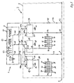
- the outer limits of the ignition lock 1 are schematized shown in dash-dotted lines with a line 2.
- the outer limits the central electrical system or the fuse box 3 are schematized also indicated by a dot-dash line 4.
- a main lead 5 leads into the central electrical system 3 or the fuse box 3.
- a first supply line 7 which is located at a second node 8 branches into two lines 9, 10.
- Line 9 runs to a first circuit breaker 12.
- the Circuit breaker 12 has a switching input 13 with which the Line 9 is conductively connected, a switching output 14, a Control input 15 and a control output or control mass 16 on.
- a supply line 17 runs from the switching output 14 a number of nodes 18 at which several consumers, in this case the consumer group usually located at terminal 15 branch off with lines 20.
- the lines 20 are in the area of the central electrical system 3 with in front of the consumers (not shown) arranged fuses 21 secured.
- the line 10 is in the same way to another Circuit breaker 24 connected, this circuit breaker 24 a switching input 25, a switching output 26, a Control input 27 and a control ground or a control output 28 has.
- Line 10 is conductive to the circuit input 25 connected.
- a line runs from circuit output 26 29 to nodes 30, of which the lines 31 of the individual consumer, in this case the consumer of the terminal 75, with fuses 32 behind the nodes 30 are arranged.
- the Circuit breaker 37 From the main feed line 5 branches at a further node 35 a further lines 36 from which to a circuit breaker 37 is performed, which switches the starter current.
- the Circuit breaker 37 has a switching input 38, a switching output 39, a control input 40 and a control output or ground connection 41.
- the supply line is at the switching output 39 39a connected to the starter.
- an ignition lock control current supply line 44 which is in the area the central electrical system 3 is secured with a fuse 45.
- This ignition lock control current lead 44 is from the central electrical system led out to the ignition lock 1.
- the ignition lock 1 is constructed in a manner known per se, with a 75 for the terminal Output 48, an output 49 for terminal 15 and for the terminal 50 an output 50 is provided. From exits 48, 49, 50 control lines 48a, 49a and 50a run to the control inputs 15, 27 and 40 of the circuit breakers 12, 24 and 37.
- In the ignition lock 1 is a separate circuit arrangement for each terminal 53 provided which four contact points 54, 55, 56 and 57 and each has a contact finger 58.
- the circuit arrangements 53 or the contact fingers 58 are together by the Turning the ignition key actuated, the first or zero position does not make contact. According to consumers the control current supply with the individual contact points of the Circuitry 53 connected so that the one Circuit 53 connected terminal in the first and / or the second and / or only the third position by contact a contact point 54, 55, 56, 57 with a contact finger 58 is operated.
- the starter is usually in the end position of the ignition lock is actuated, so that the control current lead 44 over the contact finger 58 only with the last one Contact point 57 of the circuit arrangement 53 for the terminal 50 connected is.
- control current leads 48a, 49a, 50a which out of the ignition lock 1 and into the fuse box 3 are introduced, are with the control inputs 15, 27, 40 in conductive connection, so that when in the ignition lock 1 with the contact point connected to the ignition lock control current lead 44 55, 56, 57 with the control current derivative 48a, 49a, 50a via a Contact finger 58 is connected, a control current in the Circuit breaker 12, 24, 37 flows and this to close the Switch contact between switching input 13, 25, 38 and switching output 14, 26, 39 causes.
- Control blocks which are not only as Circuit breakers serve, but also known per se represent controlled fuses, with the electronic Building blocks of the security status of the line, in particular monitors the temperature, current and / or voltage level become.
- the circuit described above can also in an equivalent manner for other switches arranged in the area of the steering column, in particular Multiple switches are used, so that from the fuse box to the multiple switches or combination switches only one control power line and one switch or switch position only one control current lead must be present a circuit breaker with the control current derivation in the fuse box or in the central electrical system.
- the currents in the central electrical system to the Consumers can flow in easier and more safely Way over stamped boards or wire grids or busbars in the central electrical system.
Landscapes
- Engineering & Computer Science (AREA)
- Mechanical Engineering (AREA)
- Details Of Connecting Devices For Male And Female Coupling (AREA)
- Keying Circuit Devices (AREA)
- Lock And Its Accessories (AREA)
Description
Claims (10)
- Schaltungsanordnung in der Kraftfahrzeugelektrik für elektrische Verbraucher, deren elektrische Zuleitungen von einer Sicherungsbox bzw. einer Zentralelektrik aus zu den Verbrauchern führen, wobei die Zuleitungen in der Zentralelektrik mit Sicherungen abgesichert sind,
wobei Schalter, insbesondere ein Zündschlossschalter vorhanden sind, welche außerhalb der Zentralelektrik bzw. der Sicherungsbox angeordnet sind, mit welchen die elektrischen Verbraucher geschaltet werden, und
wobei für die von außerhalb der Zentralelektrik angeordneten Schaltern zu schaltenden Verbraucher oder Verbrauchergruppen Leistungsschalter in der Zuleitung zu diesen Verbrauchern bzw. Verbrauchergruppen in der Zentralelektrik bzw. an der Sicherungs-Box angeordnet sind und mit diesen Schaltern, z. B. dem Zündschloss, derart verbunden sind, dass die Leistungsschalter mit diesen Schaltern z.B. Zündschloß, geschaltet werden und damit die Verbraucher bzw. Verbrauchergruppen des jeweiligen, in der Zentralelektrik bzw. an der Sicherungs-Box angeordneten Leistungsschalters indirekt mit dem außerhalb der Zentralelektrik angeordneten Schalter, insbesondere dem Zündschloss, geschaltet werden, dadurch gekennzeichnet daß an einem Knotenpunkt (43) von der Hauptzuleitung (5) eine Zündschloss-Steuerstromzuleitung (44) abzweigt, wobei im Bereich der Zentralelektrik (3) eine Sicherung (45) in der Zündschloss-Steuerstromzuleitung (44) vorgesehen ist, wobei die Zündschloss-Steuerstromzuleitung (44) aus der Zentralelektrik (3) heraus zum Zündschloss (1) geführt ist, wobei das Zündschloss (1) für die vom Zündschloss zu schaltenden Klemmen 15, 50, 75 Schaltausgänge (48, 49, 50) aufweist und von den Ausgängen (48, 49, 50) Steuerleitungen (48a, 49a, 50a) zu den Steuereingängen (15, 27, 40) der Leistungsschalter (12, 24, 37) geführt sind. - Schaltungsanordnung nach Anspruch 1,
dadurch gekennzeichnet, daß für die von in bzw. an der Lenksäule angeordneten Schalter zu schaltenden Verbraucher oder Verbrauchergruppen Leistungsschalter in der Zentralelektrik vorhanden sind und mit den in bzw. an der Lenksäule angeordneten Schaltern derart verbunden sind, daß die Leistungsschalter für die Verbraucher mit den an der Lenksäule angeordneten Schaltern geschaltet werden. - Schaltungsanordnung nach Anspruch 1 und/oder 2,
dadurch gekennzeichnet, daß die Leistungsschalter Relais sind. - Schaltungsanordnung nach Anspruch 1 und/oder 2,
dadurch gekennzeichnet, daß die Leistungsschalter elektronische Leistungsschalter sind. - Schaltungsanordnung nach Anspruch 4,
dadurch gekennzeichnet, daß die elektronischen Leistungsschalter als elektronisch gesteuerter Sicherungen für die zu schaltenden Verbraucher und deren Leitungen ausgebildet sind. - Schaltungsanordnung nach einem oder mehreren der vorhergehenden Ansprüche,
dadurch gekennzeichnet, daß zu einem Steuerschalter, der mehrere Leistungsschalter steuert, lediglich eine Steuerstromzuleitung und pro Leistungsschalter eine Steuerstromableitung vorhanden ist. - Schaltungsanordnung nach einem oder mehreren der vorhergehenden Ansprüche,
dadurch gekennzeichnet, daß von der Stromquelle des Kraftfahrzeuges eine Hauptstromzuleitung (5) in die Zentralelektrik (3) bzw. den Sicherungskasten (3) führt, wobei von der Hauptzuleitung (5) im Bereich der Zentralelektrik (3) Leitungen (7, 9,10, 36, 44) zu den Schalteingängen der Leistungsschalter führen und von den Schaltausgängen der Leistungsschalter Zuleitungen zu den Verbrauchern führen, wobei im Bereich der Zentralelektrik bzw. des Sicherungskastens in den Verbraucherzuleitungen Sicherungen angeordnet sind. - Schaltungsanordnung nach einem oder mehreren der vorhergehenden Ansprüche,
dadurch gekennzeichnet, daß von der Hauptzuleitung (5) an einem ersten Knotenpunkt (6) eine erste Zuleitung (7) abzweigt, welche sich an einem zweiten Knotenpunkt (8) in zwei Leitungen (9, 10) verzweigt, wobei die Leitung (9) zu einem ersten Leistungsschalter (12) führt und mit einem Schalteingang (13) des Leistungsschalters (12) leitend verbunden ist, wobei an einem Schaltausgang (14) des Leistungsschalters (12) eine Versorgungsleitung (17) zu einer Reihe von Knotenpunkten (18) geführt ist, an denen mehrere Verbraucher mit Leitungen (20) abzweigen. - Schaltungsanordnung nach einem oder mehreren der vorhergehenden Ansprüche,
dadurch gekennzeichnet, daß die Leitung (10) an einen Schalteingang (25) eines Leistungsschalters (24) angeschlossen ist, wobei vom Schaltungsausgang (26) eine Leitung (29) zu Knotenpunkten (30) verläuft, von denen Leitungen (31) von Verbrauchern, insbesondere von Verbrauchern der Fahrzeugklemme 75 abgehen. - Schaltungsanordnung nach einem oder mehreren der vorhergehenden Ansprüche,
dadurch gekennzeichnet, daß von der Hauptzuleitung (5) an einem Knotenpunkt (35) eine Leitung (36) abzweigt, welche zu einem Leistungsschalter (37) geführt ist und mit einem Schalteingang (38) des Leistungsschalters (37) leitend in Verbindung steht, wobei an dem Schaltausgang (39) eine Zuleitung (39a) zum Anlasser des Kraftfahrzeuges führt.
Applications Claiming Priority (2)
| Application Number | Priority Date | Filing Date | Title |
|---|---|---|---|
| DE19813473 | 1998-03-26 | ||
| DE19813473A DE19813473A1 (de) | 1998-03-26 | 1998-03-26 | Schaltungsanordnung für die Kraftfahrzeugelektronik |
Publications (3)
| Publication Number | Publication Date |
|---|---|
| EP0945308A2 EP0945308A2 (de) | 1999-09-29 |
| EP0945308A3 EP0945308A3 (de) | 2002-06-05 |
| EP0945308B1 true EP0945308B1 (de) | 2004-10-06 |
Family
ID=7862488
Family Applications (1)
| Application Number | Title | Priority Date | Filing Date |
|---|---|---|---|
| EP99105518A Expired - Lifetime EP0945308B1 (de) | 1998-03-26 | 1999-03-18 | Schaltungsanordnung für die Kraftfahrzeugelektrik |
Country Status (2)
| Country | Link |
|---|---|
| EP (1) | EP0945308B1 (de) |
| DE (2) | DE19813473A1 (de) |
Families Citing this family (2)
| Publication number | Priority date | Publication date | Assignee | Title |
|---|---|---|---|---|
| US9802558B2 (en) * | 2013-09-27 | 2017-10-31 | GM Global Technology Operations LLC | Distributed vehicle battery high-voltage bus systems and methods |
| DE102018212507A1 (de) * | 2018-07-26 | 2020-01-30 | Robert Bosch Gmbh | Elektronischer Leistungsverteiler |
Family Cites Families (6)
| Publication number | Priority date | Publication date | Assignee | Title |
|---|---|---|---|---|
| DE3535860A1 (de) * | 1985-10-08 | 1987-04-09 | Joachim Dipl Phys Schick | Verdrahtungsanordnung fuer kraftfahrzeuge |
| DE3930153A1 (de) * | 1989-09-09 | 1991-03-21 | Rheydt Kabelwerk Ag | Verkabelungssystem fuer fahrzeuge |
| FR2690601B1 (fr) * | 1992-04-22 | 2002-02-01 | Valeo Electronique | Platine de servitude pour la commande et/ou l'alimentation d'organes électriques de véhicules. |
| DE4233865A1 (de) * | 1992-10-08 | 1994-04-14 | Bosch Gmbh Robert | Bedienvorrichtung für elektrische Verbraucher, wie Blinker, Scheinwerfer, Scheibenwischer o. dgl. in einem Fahrzeug |
| DE4329860A1 (de) * | 1993-09-03 | 1995-03-09 | Hotzenblitz Mobile Gmbh Co Kg | Schaltungsanordnung zur Steuerung unterschiedlicher elektrischer Verbraucher in einem Kraftfahrzeug |
| DE19526809A1 (de) * | 1995-07-13 | 1997-01-16 | Siemens Ag | Bordnetz mit Multiplexsteuerung für Kraftfahrzeuge |
-
1998
- 1998-03-26 DE DE19813473A patent/DE19813473A1/de not_active Withdrawn
-
1999
- 1999-03-18 EP EP99105518A patent/EP0945308B1/de not_active Expired - Lifetime
- 1999-03-18 DE DE59910683T patent/DE59910683D1/de not_active Expired - Fee Related
Also Published As
| Publication number | Publication date |
|---|---|
| EP0945308A3 (de) | 2002-06-05 |
| DE59910683D1 (de) | 2004-11-11 |
| EP0945308A2 (de) | 1999-09-29 |
| DE19813473A1 (de) | 1999-09-30 |
Similar Documents
| Publication | Publication Date | Title |
|---|---|---|
| DE102017101369B4 (de) | Energieversorgungssystem für sicherheitsrelevante systeme in einem kraftfahrzeug | |
| EP3545603B1 (de) | Zweispannungsbatterie | |
| EP3304673B1 (de) | Elektrische versorgungseinrichtung und damit ausgestattetes bordnetz eines fahrzeugs | |
| DE102011083582A1 (de) | Stromverteiler für Kraftfahrzeug-Bordnetze | |
| DE19646264A1 (de) | Schmelzleiteraufbau | |
| EP0939959B1 (de) | Elektrisch leitendes kabel | |
| DE3930153A1 (de) | Verkabelungssystem fuer fahrzeuge | |
| DE19922408A1 (de) | Bus-System mit bei Störungen automatisch abschaltbaren Teilnetzen | |
| DE10247307B3 (de) | Fahrzeugbordnetz | |
| DE4329860A1 (de) | Schaltungsanordnung zur Steuerung unterschiedlicher elektrischer Verbraucher in einem Kraftfahrzeug | |
| WO2023001947A1 (de) | Stromverteilervorrichtung und kraftfahrzeug | |
| DE2942987A1 (de) | Einrichtung zur steuerung und verteilung elektrischer leistung in einem motorfahrzeug | |
| EP0945308A2 (de) | Schaltungsanordnung für die Kraftfahrzeugelektrik | |
| DE102022106118B4 (de) | Modular aufgebaute Schaltschützbox | |
| EP1630916A1 (de) | Einspeisesystem für Niederspannungsschaltgeräte | |
| EP1570505B1 (de) | Niederspannungs-leistungsschalter | |
| DE10331823A1 (de) | Schiffs-Energieversorgungs- und -verteilungsanlage | |
| DE1900872C3 (de) | Vorrichtung zur Energieversorgung der Stromverbraucher eines Kraftfahrzeuges aus einer Stromquelle | |
| EP1353430B1 (de) | Schaltungsanordnung | |
| DE102006058587A1 (de) | Elektrischer Anschlusskasten | |
| DE102020212249B4 (de) | Schaltschrank mit einem Kabelverlegekasten | |
| DE19733019C2 (de) | Elektrische Schaltungsanordnung | |
| DE60133580T2 (de) | Elektrisch leitendes element zum uberbrücken der elektrizitätsversorgung | |
| DE102006045859A1 (de) | Potentialverteiler für Kraftfahrzeuge | |
| DE2604398C3 (de) | Schaltanordnung zum Verhindern des unbefugten Einschaltens einer Fahrtrichtungs- und Warnblinkanlage, insbesondere an offenen Kraftfahrzeugen |
Legal Events
| Date | Code | Title | Description |
|---|---|---|---|
| PUAI | Public reference made under article 153(3) epc to a published international application that has entered the european phase |
Free format text: ORIGINAL CODE: 0009012 |
|
| AK | Designated contracting states |
Kind code of ref document: A2 Designated state(s): AT BE CH CY DE DK ES FI FR GB GR IE IT LI LU MC NL PT SE |
|
| AX | Request for extension of the european patent |
Free format text: AL;LT;LV;MK;RO;SI |
|
| PUAL | Search report despatched |
Free format text: ORIGINAL CODE: 0009013 |
|
| AK | Designated contracting states |
Kind code of ref document: A3 Designated state(s): AT BE CH CY DE DK ES FI FR GB GR IE IT LI LU MC NL PT SE |
|
| AX | Request for extension of the european patent |
Free format text: AL;LT;LV;MK;RO;SI |
|
| 17P | Request for examination filed |
Effective date: 20021113 |
|
| AKX | Designation fees paid |
Designated state(s): DE FR SE |
|
| 17Q | First examination report despatched |
Effective date: 20030923 |
|
| GRAP | Despatch of communication of intention to grant a patent |
Free format text: ORIGINAL CODE: EPIDOSNIGR1 |
|
| GRAS | Grant fee paid |
Free format text: ORIGINAL CODE: EPIDOSNIGR3 |
|
| GRAA | (expected) grant |
Free format text: ORIGINAL CODE: 0009210 |
|
| RAP1 | Party data changed (applicant data changed or rights of an application transferred) |
Owner name: GHW GROTE & HARTMANN GMBH & CO. KG |
|
| AK | Designated contracting states |
Kind code of ref document: B1 Designated state(s): DE FR SE |
|
| RAP2 | Party data changed (patent owner data changed or rights of a patent transferred) |
Owner name: LEAR CORPORATION ELECTRICAL AND ELECTRONICS GMBH & |
|
| REG | Reference to a national code |
Ref country code: IE Ref legal event code: FG4D Free format text: GERMAN |
|
| REF | Corresponds to: |
Ref document number: 59910683 Country of ref document: DE Date of ref document: 20041111 Kind code of ref document: P |
|
| REG | Reference to a national code |
Ref country code: SE Ref legal event code: TRGR |
|
| REG | Reference to a national code |
Ref country code: FR Ref legal event code: CD |
|
| PG25 | Lapsed in a contracting state [announced via postgrant information from national office to epo] |
Ref country code: SE Free format text: LAPSE BECAUSE OF NON-PAYMENT OF DUE FEES Effective date: 20050319 |
|
| ET | Fr: translation filed | ||
| PLBE | No opposition filed within time limit |
Free format text: ORIGINAL CODE: 0009261 |
|
| STAA | Information on the status of an ep patent application or granted ep patent |
Free format text: STATUS: NO OPPOSITION FILED WITHIN TIME LIMIT |
|
| 26N | No opposition filed |
Effective date: 20050707 |
|
| EUG | Se: european patent has lapsed | ||
| PG25 | Lapsed in a contracting state [announced via postgrant information from national office to epo] |
Ref country code: FR Free format text: LAPSE BECAUSE OF NON-PAYMENT OF DUE FEES Effective date: 20051130 |
|
| REG | Reference to a national code |
Ref country code: FR Ref legal event code: ST Effective date: 20051130 |
|
| PGFP | Annual fee paid to national office [announced via postgrant information from national office to epo] |
Ref country code: DE Payment date: 20080430 Year of fee payment: 10 |
|
| PG25 | Lapsed in a contracting state [announced via postgrant information from national office to epo] |
Ref country code: DE Free format text: LAPSE BECAUSE OF NON-PAYMENT OF DUE FEES Effective date: 20091001 |