EP0945355A2 - Container closure having a pull tab - Google Patents
Container closure having a pull tab Download PDFInfo
- Publication number
- EP0945355A2 EP0945355A2 EP99302299A EP99302299A EP0945355A2 EP 0945355 A2 EP0945355 A2 EP 0945355A2 EP 99302299 A EP99302299 A EP 99302299A EP 99302299 A EP99302299 A EP 99302299A EP 0945355 A2 EP0945355 A2 EP 0945355A2
- Authority
- EP
- European Patent Office
- Prior art keywords
- panel section
- pulling tab
- plastic material
- pulling
- container
- Prior art date
- Legal status (The legal status is an assumption and is not a legal conclusion. Google has not performed a legal analysis and makes no representation as to the accuracy of the status listed.)
- Withdrawn
Links
Images


Classifications
-
- B—PERFORMING OPERATIONS; TRANSPORTING
- B65—CONVEYING; PACKING; STORING; HANDLING THIN OR FILAMENTARY MATERIAL
- B65D—CONTAINERS FOR STORAGE OR TRANSPORT OF ARTICLES OR MATERIALS, e.g. BAGS, BARRELS, BOTTLES, BOXES, CANS, CARTONS, CRATES, DRUMS, JARS, TANKS, HOPPERS, FORWARDING CONTAINERS; ACCESSORIES, CLOSURES, OR FITTINGS THEREFOR; PACKAGING ELEMENTS; PACKAGES
- B65D17/00—Rigid or semi-rigid containers specially constructed to be opened by cutting or piercing, or by tearing of frangible members or portions
- B65D17/28—Rigid or semi-rigid containers specially constructed to be opened by cutting or piercing, or by tearing of frangible members or portions at lines or points of weakness
- B65D17/401—Rigid or semi-rigid containers specially constructed to be opened by cutting or piercing, or by tearing of frangible members or portions at lines or points of weakness characterised by having the line of weakness provided in an end wall
- B65D17/4011—Rigid or semi-rigid containers specially constructed to be opened by cutting or piercing, or by tearing of frangible members or portions at lines or points of weakness characterised by having the line of weakness provided in an end wall for opening completely by means of a tearing tab
-
- B—PERFORMING OPERATIONS; TRANSPORTING
- B65—CONVEYING; PACKING; STORING; HANDLING THIN OR FILAMENTARY MATERIAL
- B65D—CONTAINERS FOR STORAGE OR TRANSPORT OF ARTICLES OR MATERIALS, e.g. BAGS, BARRELS, BOTTLES, BOXES, CANS, CARTONS, CRATES, DRUMS, JARS, TANKS, HOPPERS, FORWARDING CONTAINERS; ACCESSORIES, CLOSURES, OR FITTINGS THEREFOR; PACKAGING ELEMENTS; PACKAGES
- B65D2517/00—Containers specially constructed to be opened by cutting, piercing or tearing of wall portions, e.g. preserving cans or tins
- B65D2517/0001—Details
- B65D2517/001—Action for opening container
- B65D2517/0016—Action for opening container pivot tab, push-down and pull-out tear panel
-
- B—PERFORMING OPERATIONS; TRANSPORTING
- B65—CONVEYING; PACKING; STORING; HANDLING THIN OR FILAMENTARY MATERIAL
- B65D—CONTAINERS FOR STORAGE OR TRANSPORT OF ARTICLES OR MATERIALS, e.g. BAGS, BARRELS, BOTTLES, BOXES, CANS, CARTONS, CRATES, DRUMS, JARS, TANKS, HOPPERS, FORWARDING CONTAINERS; ACCESSORIES, CLOSURES, OR FITTINGS THEREFOR; PACKAGING ELEMENTS; PACKAGES
- B65D2517/00—Containers specially constructed to be opened by cutting, piercing or tearing of wall portions, e.g. preserving cans or tins
- B65D2517/0001—Details
- B65D2517/0058—Other details of container end panel
- B65D2517/008—Materials of container end panel
- B65D2517/0085—Foil-like, e.g. paper or cardboard
- B65D2517/0088—Foil-like, e.g. paper or cardboard with plastic overmoulded onto foil
Definitions
- the present invention relates to a container closure having a pulling tab for opening the container in which the closure is attached, in particular, to a container closure comprising a peripheral section adapted to be attached to a peripheral edge of an opening of a container body, a panel section surrounded by the peripheral section, a score portion formed on the periphery of the panel section for providing a weakened region, and a pulling tab provided on said panel section for allowing said container to be opened by separating the panel section along said score portion from said peripheral section by pulling said pulling tab up.
- the present invention though not limited to any specific use, is effective when applied to a container closure in which at least portions of the panel portion and the pulling tab are formed by molding a plastic material.
- a closure for this type of container is structured to have a score line for breaking the closure so that the container is opened by pulling a pulling tab provided to the closure to thereby break the closure along the score line.
- Conventional container closures provided with this type of pulling tab may include those which are totally or substantially formed of a metallic material and those which are formed of a plastic material by injection molding.
- the closure using plastic material generally has a gas barrier layer whose major component is aluminum foil which is covered by layers of a plastic material formed by injection-molding on either or both sides of the gas barrier layer.
- a rim At the peripheral section formed is a rim to be attached to a peripheral edge portion of the opening of the container body.
- the pulling tab is also formed of the metallic material and is riveted to the closure body.
- the pulling tab is also formed of a plastic material and bonded to the closure body through a suitable bonding technique such as by an ultrasonic welding, as described in the Japanese Laid-open Patent Publications Nos. Sho 62-168852 and Sho 63-44441.
- the pulling tab is disposed substantially in parallel with the plane of the closure panel.
- the pulling tab has first to be pulled up.
- the pulling tab has a front end portion which is generally disposed in the vicinity of the score line.
- the pulling tab of the conventional structure is, however, not easy to handle particularly in the initial stage of opening process.
- the tab has to be raised to a certain angle with respect to the plane of the closure panel, however, this task is not easy since the pulling tab is disposed nearly parallel to the container panel.
- the pulling tab is formed separately from container body and later attached to the container body, an additional manufacturing process is required, and therefore, cost for the product is increased.
- Japanese Patent Publication No. Hei 4-55564 discloses a manufacturing process, which uses a prefabricated pulling tab formed at the portion to be fixed to the container body with an attachment aperture. The pulling tab is then placed in the mold together with the gas barrier multi-layered sheet and molten plastic material is then injected into the mold cavity. This process also requires steps of molding a pulling tab and then molding a closure using this molded pulling tab. Thus, complicated process steps are required.
- Japanese Laid-Open Patent Publication No. Sho 59-221256 discloses a process in which the pulling tab is simultaneously molded together with the panel portion.
- the panel portion is formed by injection-molding a plastic material layer onto a multi-layered sheet including a gas barrier material.
- the multi-layered sheet is in advance applied at an area where the pulling tab is to be molded (hereafter referred to as "pulling tab molding area") with a separating agent, and plastic material is injected thereon.
- a groove is formed around the pulling tab molding area for separating the pulling tab molding area from its outside area.
- the method described in this Japanese Laid-Open Patent Publication has an advantage in that the pulling tab of the container and the container body can be molded at the same time. It should however be noted that the method is disadvantageous in that an additional step of applying the separating agent is required. Further, it should be noted that, in the proposed process, it is also required to make a precise registration of the area where the separating agent to be applied. Another problem which may be encountered in this process is that the separating agent may be removed during the molding due to the heat and flow of the injected molten plastic material.
- Another object of the present invention is to provide a method for manufacturing such container closure.
- the present invention provides a container closure comprising a peripheral section adapted to be attached to a peripheral edge portion of an opening of a container body, a panel section covering an area surrounded by said peripheral section.
- the closure includes a score portion formed along the periphery of the panel section to provide a weakened region.
- a pulling tab is attached to the panel section by pulling the pulling tab up to thereby separate the panel section from the peripheral section along the score line.
- On the panel section there is provided a projection extending laterally with respect to the pulling tab at a position adjacent to the front end portion of the pulling tab.
- the pulling tab has an abutting end portion at the front end portion for engagement with the projection when the pulling tab is pulled up by a predetermined angle with respect to the panel section and for causing the panel section to be broken along the score portion by pushing the projection as the pulling tab is further pulled up.
- This container closure may be formed of any material.
- a container closure in accordance with the present invention suitable for manufacture by a plastic molding comprises a peripheral section adapted to be attached to a peripheral edge portion of an opening of a container body and a panel section covering an area surrounded by the peripheral section.
- the panel section includes a substrate of gas blocking property having a layer of a plastic material formed on at least one side thereof.
- the closure further includes a score portion formed along a periphery of the panel section to provide a weakened region.
- a pulling tab is attached to the panel section for allowing a container to be opened by pulling the pulling tab up to thereby separate the panel section from the peripheral section along the score portion.
- the pulling tab is integrally molded together with the plastic material layer of the panel section through a thin walled hinge portion so that the pulling tab can be pulled up with respect to the panel section.
- a projection is molded integrally with the plastic material layer of the panel section adjacent to a front end portion of the pulling tab.
- the projection is made of a plastic material and extends laterally with respect to the pulling tab.
- An abutting end portion is formed at the front end of the pulling tab and adapted to be brought into engagement with the projection when said pulling tab is pulled up by a predetermined angle with respect to the panel section to cause the panel section to be broken along the score portion by pushing the projection as the pulling tab is further pulled up with respect to the panel section.
- the score portion may be formed by molding the plastic layer in the panel section in a manner that the the plastic material of the panel section is interrupted and the gas blocking substrate is thus exposed at the area of the score portion.
- a holding portion is desirably formed at the panel section for releasably holding the pulling tab substantially in parallel with and close to the panel section.
- the projection desirably comprises a ridge extending laterally with respect to the pulling tab, and a reinforcement extending at a side opposite to the pulling tab with respect to the ridge in a direction intersecting the ridge for transmitting a pushing force.
- the reinforcement for transmitting pushing force is desirably formed to extend to a position close to the score portion.
- a preferable operation of the pulling tab can be obtained if the angle for the pulling tab is determined so that the abutting end portion of the front end of the pulling tab is brought into contact with the projection when the pulling tab is raised to an angle between 30 and 90 degrees with respect to the panel section.
- a heat sealable material layer may be applied on the side opposite to the pulling tab.
- the container closure may then be fastened to the peripheral edge portion of the opening of the container body at the area of this heat sealable material.
- the present invention also provides a method for molding the above mentioned container closure through a plastic molding.
- the method comprises the steps of providing a lower mold part having a molding face for supporting the gas blocking substrate, at least one slide core having a molding face for molding a part of an upper face of the panel section and a lower face of the pulling tab including the hinge portion with the pulling tab positioned with an angle smaller than the aforementioned predetermined angle with respect to the panel section, and an upper mold part having a molding face for forming a molding cavity together with the slide core and the lower mold, and then injecting a molten plastic material into the molding cavity, and thereafter removing the upper mold after the plastic material has been solidified, removing the slide core and taking out a molded product, molded pulling tab being deflected while the molded product is being taken out in the direction to increase the angle between the molded pulling tab and the panel section in the molded product.
- a container closure of the present invention In a container closure of the present invention, at the initial stage of raising the pulling tab with respect to the panel face, no force for opening a container is applied to said pulling tab. Therefore, the pulling tab can easily be raised when the container is to be opened. after the front end of the pulling tab comes into contact with the projection, further lifting movement of the pulling tab in a direction to raise the pulling tab causes a force to be added from the projection to the score line of the panel section, and then the panel section is broken off along the score line.
- the projection comprises a ridge extending laterally with respect to the pulling tab and a reinforcement extending at a side opposite to the pulling tab with respect to the ridge in a direction intersecting the ridge for transmitting pushing force
- a breaking force can effectively be applied to the score line by locating the front end of said reinforcement in the vicinity of the score line.
- a container closure can easily manufactured in a single process using a molding die having the aforementioned slide core.
- the pulling tab since a pulling tab is molded in a manner that it is allowed to swing around a hinge with respect to the panel section of the container closure, the pulling tab can be easily removed from the mold because the pulling tab can be deflected at its hinge Portion. Further, no additional process for attaching the pulling tab is necessary after the closure has been molded.
- the present invention will hereafter be described taking reference to the accompanying drawings which show an embodiment thereof.
- the gas blocking substrate 1 comprises a thin sheet 2 which may be a metal foil such as aluminum foil, iron foil, and the like, or a sheet of any other material of gas blocking property such as saponified ethylene vinyl acetate copolymer, poly-vinylidene chloride, poly-amide, poly-acrylo nitrile, or the like.
- Layers 3, 4 of a heat-fusible plastic material are formed on the opposite surfaces of the sheet 2.
- the layer 3 is provided to cover the upper face of the sheet 2 and made of a material capable of forming an intimate layer together with a plastic layer which will be formed in later stage by injection molding over the gas barrier substrate 1.
- Materials which can be used for this purpose include polypropylene, polyethylene, polyester, polyamide, polycarbonate, polystyrene, and the like. In case of a container for retort pouch food, polypropylene is preferable.
- the plastic material layer 4 is provided on the lower face of the sheet 2 and is adapted for heat sealing the closure to the peripheral edge portion of the top opening of a container body.
- Preferable materials for this purpose consiste polypropylene, polyethylene, polyester, polyamide, polycarbonate, polyacrylo nitrile, polystyrene, or any other adhesive materials such as maleic anhydride graft polymerised carboxyl group denatured polypropylene, carboxyl group denatured linear low density polyethylene.
- Figs. 2 and 3 show a container closure 5 embodying the present invention.
- the closure 5 comprises a gas blocking substrate 1 shown in Fig.1 and a layer 6 of a plastic material formed on the upper face of the substrate 1.
- the container closure 5 comprises a planar panel section 5a which is shaped to conform with a top opening of a container body (not illustrated) such as a can and an annular peripheral section 5b including a raised ridge portion formed along a periphery of the panel section 5a.
- the peripheral section of the gas blocking substrate 1 is bent to form a substantially Z-shaped cross-section as shown in Figs. 2 and 4.
- the peripheral section of the plastic material layer 6 has a portion which is laid over the peripheral portion of the gas blocking substrate 1 and the outer fringe of the plastic material layer 6 is further bent downward to form-a downwardly opening annular groove.
- a score line 7 is formed substantially along the inner circumference of the peripheral section 5b of the container closure 5.
- the score line 7 is formed by making the plastic material layer 6 to be discontinuous to thereby expose the gas blocking substrate 1.
- a pulling tab 8 which is integrally molded together with the plastic material layer 6.
- a groove 5c is formed in the plastic material layer 6 on the panel section 5a to extend in the direction of a chord of the panel section 5a at a position corresponding to the front end of the pulling tab. This groove 5c is formed by providing a thin walled portion in the plastic material layer 6 on the panel section 5a.
- the pulling tab 8 is connected through a thin walled hinge portion 8a to the plastic material layer 6 on the panel section 5a.
- the pulling tab 8 is a substantially planar configuration having an aperture 8b for accommodating a finger for opening the closure.
- the thickness of the tab 8 is substantially uniform throughout the length as shown in Fig. 2. In a preferable embodiment, the thickness of the pulling tab is approximately 0.5 mm to 5.0 mm and that of the hinge portion is approximately 50 ⁇ m to 500 ⁇ m.
- a projection 9 is formed and located adjacent to the front end portion 8c of the pulling tab 8.
- This projection 9 comprises a ridge 9a which is located outside the groove 5c at a position close to the score line.
- the ridge 9a extends along the score line 5c.
- the reinforcement 9b is formed integrally with the ridge 9a so as to extend outwards from the central portion of the ridge 9a toward the score line 7.
- the ridge 9a of the projection 9 has a slant face 9c which is adapted to be brought into contact with the front end of the pulling tab 8 (hereafter referred to as a slant contacting face 9C) when the pulling tab 8 is pulled up from the panel 5a.
- a pair of holding portions 10 are formed on the upper face of the plastic material layer 6 of the panel section 5a of the container closure 5. These holding portions 10 resiliently hold the pulling tab 8 at both sides thereof and thereby function so that the pulling tab 8 is held substantially in parallel with the panel section 5a as shown in Figs. 4a, 4b.
- a V-notch having an including angle ⁇ is formed between the front end 8c of the pulling tab 8 and the slant contacting face 9c of the ridge 9a of the projection 9.
- the container closure 5 shown in Fig. 4 is heat sealed to the peripheral edge portion of the upper opening of the container body 11.
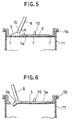
- the pulling tab 8 When it is desired to open the closure, the pulling tab 8 is pulled up from the face of the panel section 6 to the position shown in Fig. 5, so that the front end 8c of the pulling tab 8 is brought into contact with the slant contacting face 9c formed on the ridge 9a of the projection 9.
- the front end 8c of the pulling tab 8 contacts with the slant contacting face 9c formed at the ridge 9a of the projection 9.
- the reinforcement 9b of the projection 9 penetrates into the gas blocking substrate 1 of the panel section 5a so that the panel section 5a is broken along the score line 7 as shown in Fig. 6.
- the pulling tab 8 is further pulled up, to cause the panel section 5a of the closure 5 to be separated along the score line 7 from the peripheral section 5b.
- the angle ⁇ is preferably determined to be between 30 and 90 degrees but a larger angle up to 120 degrees, for example, may be adopted.
- the score line 7 is formed by making the plastic material to be discontinuous to thereby expose the gas blocking substrate.
- the thickness of the sheet 2 of the gas blocking substrate 1 is preferably determined to be less than 50 ⁇ m and preferably about between 9 ⁇ m and 30 ⁇ m.
- the thickness of each of the plastic material layers 3, 4 is preferably less than 100 ⁇ m.
- the width of the score line 7 should not be so large and is preferably less than 2.0 mm and more preferably less than 1.0 mm.
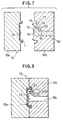
- Fig. 7 shows an injection mold assembly 12 employed for molding a container closure 5 of an embodiment of the present invention.
- the mold 12 comprises a lower mold 12a, an upper mold 12b, and a slide core 12c.
- the lower mold 12a has a recessed mold portion 13 for disposing the gas blocking substrate 1 of the container closure 5.
- the slide core 12c is arranged so as to slide up and down in the upper mold 12b.
- the slide core 12c is provided at its lower end with a flat plane 14 for forming the upper face of the plastic material layer 6 and a recess 15 for forming the holding portions 10.
- the slide core 12c is provided with an upwardly facing molding face 16 which is slanted with respect to the flat plane 14 by a predetermined angle for forming the pulling tab 8.
- the inclination angle of the molding face 16 with respect to the flat face 14 is smaller than the angle ⁇ described above.
- the upper mold 12b comprises a molding recess 17 for molding the peripheral section 5b and an annular projection 18 for forming the score line 7. Further the upper mold 12b comprises a molding face 19 adapted to cooperate with the molding face 16 of the slide core 12c for molding the pulling tab and a projection 20 for forming the hinge portion 8a.
- the gas blocking substrate 1 is disposed on the mold recess portion 13 of the lower mold 12a, and the upper mold 12b is then placed on the lower mold 12a to form a molding cavity for injecting molten plastic material.
- the upper mold 12b comprises two injection gates 21, 22 for injecting the molten plastic material into the molding cavity.
- the gate 21 is open to the cavity at a position corresponding to the peripheral section 5b of the container closure 5.
- the gate 22 is open to the cavity at a position corresponding the projection 9.
- molten plastic material is injected from the gates 21, 22 into the mold to completely fill the cavity.
- the injected plastic material forms the plastic material layer 6 on the gas blocking substrate 1.
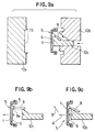
- the upper mold 12b is separated from the lower mold 12a as shown in Fig. 9a.
- the slide core 12c is also separated from the lower mold 12b.
- the molded container closure 5 is separated together with the slide core 12c from the lower mold 12a and the upper mold 12b.
- the pulling tab 8 on the molded product is deflected around its hinge portion 8a and thereby the molded container closure 5 is removed from the slide core 12c.
- Fig. 9c shows another method for removing the molded container closure 5 from the slide core 12c.
- the molded container closure 5 is moved downwards a little with respect to the slide core 12c.
- the molded pulling tab 8 is deflected only a bit. Then, by moving the container closure 5 obliquely in the direction as indicated by an arrow B, the container closure 5 can be removed from the slide core 12c.
- Materials such as polypropylene, polyethylene, polyester, polyamide, polycarbonate, and polystyrene may be used for molding the plastic material layer 6.
- An inorganic filler may be mixed to these materials.
- the mixed inorganic filler improves the dimensional stability of the container closure and reduces the thermal contraction rate. Further, the addition of such inorganic material is effective to improve thermal resistance, with the result that the thermal deformation temperature can be increased, and the thermal conductivity can be improved.
- Such property of the closure is preferable for use with a container for retort pouch food. Further, it should be noted that, in disposing the container closure after use, the thermal calorie produced during the incineration can be decreased. This property is effective to protect the incinerator from thermal damage.
- the added inorganic filler can give the container closure more rigidity which provides advantages for the distribution of product.
- an inorganic filler those employed as additives in the fields of synthetic plastic material or rubber are available.
- any substance may be employed so long as it is an inorganic compound inactive to oxygen and water, preferable in terms of food sanitation, and not dissolvable during the process of kneading and molding.
- materials such as compounds like metal oxide, hydrate (hydroxide) thereof, sulfate, carbonate, silicate of a metal, and their double salts, or their compounds.
- materials which may be used for the purpose include aluminum hydrate, calcium hydrate, magnesium hydrate, zinc oxide, red lead, magnesium carbonate, calcium carbonate, white carbon, talc, mica, glass fiber, glass powder, glass beads, diatomaceous earth, silica, wollastonite, iron oxide, titanium oxide, lithopone, pumice powder, gypsum, barium carbonate, dolomite, and iron sand.
- those in powder form preferably have a diameter less than 20 ⁇ m, more preferably less than 10 ⁇ m.
- Those in fiber form preferably are from 1 to 500 ⁇ m in diameter, more preferably from 1 to 300 ⁇ m, and are from 0.1 to 6 mm in length, more preferably from 0.1 to 5 mm.
- Those in planar form are preferably less than 30 ⁇ m in diameter, more preferably from 1 to 10 ⁇ m.
- these inorganic fillers those of planar or powder form are especially preferable.
- various additives including pigment may be added to the plastic material for use in the injection molding.
- MFR ethylene propylene block copolymer
- MFR 20
- the layer functions as a heat fusible layer adapted to be integrated with an injection plastic material whch will be injected on the substrate 1 in a later stage.
- the multi-layered substrate 1 was disposed in the recessed mold portion 13 of the lower mold 12a of the mold 12 shown in Fig. 8, and ethylene propylene block copolymer(Showa Denko ShowAromer MK-451-2) was injected through the gates 21, 22 shown in Fig. 8 by an injection molding machine Toshiba IS50A(302) with the temperature and pressure at the injection cylinder being set at 240°C and 60 Kg/cm 2 respectively and thereby a container closure 5 shown in Figs. 2, 3 was molded.
- a polypropylene container was fully filled with water of 230g and the container closure was heat sealed by high frequency sealing process and a retort sterilization at 125°C for 30 minutes was then implemented to make the test sample.
- Drop strength was evaluated by dropping a container fully filled with water onto a concrete floor.
- the container was dropped in a direction that the joint portion of the closure and the container body on the side of the front end of the pulling tab would first hit the floor.
- the drop height in the test was incrementally changed from 50 cm by every 10 cm.
- the denominator and the numerator are the number of tested samples and the number of broken samples, respectively. In all samples, the breakage occurred at the score line of the container closure. As seen from Table 2, the container closure of the present invention has a high strength against breakage.
- the present invention can provide a container closure which can be readily manufactured and easy to open. Further, the container closure of the present invention has a higher drop strength than that of the prior art.
Landscapes
- Engineering & Computer Science (AREA)
- Mechanical Engineering (AREA)
- Containers Opened By Tearing Frangible Portions (AREA)
- Closures For Containers (AREA)
Abstract
Description
- The present invention relates to a container closure having a pulling tab for opening the container in which the closure is attached, in particular, to a container closure comprising a peripheral section adapted to be attached to a peripheral edge of an opening of a container body, a panel section surrounded by the peripheral section, a score portion formed on the periphery of the panel section for providing a weakened region, and a pulling tab provided on said panel section for allowing said container to be opened by separating the panel section along said score portion from said peripheral section by pulling said pulling tab up. The present invention, though not limited to any specific use, is effective when applied to a container closure in which at least portions of the panel portion and the pulling tab are formed by molding a plastic material.
- It is common to store beverage and food in a container like a can and close the container tightly with a sealing closure for preservation or sales display at shop front. A closure for this type of container is structured to have a score line for breaking the closure so that the container is opened by pulling a pulling tab provided to the closure to thereby break the closure along the score line.
- Conventional container closures provided with this type of pulling tab may include those which are totally or substantially formed of a metallic material and those which are formed of a plastic material by injection molding. The closure using plastic material generally has a gas barrier layer whose major component is aluminum foil which is covered by layers of a plastic material formed by injection-molding on either or both sides of the gas barrier layer. At the peripheral section formed is a rim to be attached to a peripheral edge portion of the opening of the container body. In the case where the major component of the container closure is formed of a metallic material, the pulling tab is also formed of the metallic material and is riveted to the closure body. In the case where the major component of the container closure is formed out of a plastic material, the pulling tab is also formed of a plastic material and bonded to the closure body through a suitable bonding technique such as by an ultrasonic welding, as described in the Japanese Laid-open Patent Publications Nos. Sho 62-168852 and Sho 63-44441.
- In either case, the pulling tab is disposed substantially in parallel with the plane of the closure panel. When it is desired to open the closure, the pulling tab has first to be pulled up. The pulling tab has a front end portion which is generally disposed in the vicinity of the score line. As the pulling tab is pulled up, the front end portion is pushed downward by leverage effect. The pulling tab of the conventional structure is, however, not easy to handle particularly in the initial stage of opening process. When the pulling tab is being pulled up in the initial stage of opening process, the tab has to be raised to a certain angle with respect to the plane of the closure panel, however, this task is not easy since the pulling tab is disposed nearly parallel to the container panel. Further, since the pulling tab is formed separately from container body and later attached to the container body, an additional manufacturing process is required, and therefore, cost for the product is increased.
- Japanese Patent Publication No. Hei 4-55564 discloses a manufacturing process, which uses a prefabricated pulling tab formed at the portion to be fixed to the container body with an attachment aperture. The pulling tab is then placed in the mold together with the gas barrier multi-layered sheet and molten plastic material is then injected into the mold cavity. This process also requires steps of molding a pulling tab and then molding a closure using this molded pulling tab. Thus, complicated process steps are required.
- Japanese Laid-Open Patent Publication No. Sho 59-221256 discloses a process in which the pulling tab is simultaneously molded together with the panel portion. In this process, the panel portion is formed by injection-molding a plastic material layer onto a multi-layered sheet including a gas barrier material. In the method disclosed in this Japanese Laid-Open Patent Publication, the multi-layered sheet is in advance applied at an area where the pulling tab is to be molded (hereafter referred to as "pulling tab molding area") with a separating agent, and plastic material is injected thereon. A groove is formed around the pulling tab molding area for separating the pulling tab molding area from its outside area.
- The method described in this Japanese Laid-Open Patent Publication has an advantage in that the pulling tab of the container and the container body can be molded at the same time. It should however be noted that the method is disadvantageous in that an additional step of applying the separating agent is required. Further, it should be noted that, in the proposed process, it is also required to make a precise registration of the area where the separating agent to be applied. Another problem which may be encountered in this process is that the separating agent may be removed during the molding due to the heat and flow of the injected molten plastic material.
- It is therefore an object of the present invention to provide a container closure which is easy to manufacture and convenient to open.
- Another object of the present invention is to provide a method for manufacturing such container closure.
- In order to accomplish the above and other objects, the present invention provides a container closure comprising a peripheral section adapted to be attached to a peripheral edge portion of an opening of a container body, a panel section covering an area surrounded by said peripheral section. The closure includes a score portion formed along the periphery of the panel section to provide a weakened region. A pulling tab is attached to the panel section by pulling the pulling tab up to thereby separate the panel section from the peripheral section along the score line. On the panel section, there is provided a projection extending laterally with respect to the pulling tab at a position adjacent to the front end portion of the pulling tab. The pulling tab has an abutting end portion at the front end portion for engagement with the projection when the pulling tab is pulled up by a predetermined angle with respect to the panel section and for causing the panel section to be broken along the score portion by pushing the projection as the pulling tab is further pulled up. This container closure may be formed of any material.
- A container closure in accordance with the present invention suitable for manufacture by a plastic molding comprises a peripheral section adapted to be attached to a peripheral edge portion of an opening of a container body and a panel section covering an area surrounded by the peripheral section. The panel section includes a substrate of gas blocking property having a layer of a plastic material formed on at least one side thereof. The closure further includes a score portion formed along a periphery of the panel section to provide a weakened region. A pulling tab is attached to the panel section for allowing a container to be opened by pulling the pulling tab up to thereby separate the panel section from the peripheral section along the score portion. The pulling tab is integrally molded together with the plastic material layer of the panel section through a thin walled hinge portion so that the pulling tab can be pulled up with respect to the panel section. A projection is molded integrally with the plastic material layer of the panel section adjacent to a front end portion of the pulling tab. The projection is made of a plastic material and extends laterally with respect to the pulling tab. An abutting end portion is formed at the front end of the pulling tab and adapted to be brought into engagement with the projection when said pulling tab is pulled up by a predetermined angle with respect to the panel section to cause the panel section to be broken along the score portion by pushing the projection as the pulling tab is further pulled up with respect to the panel section. The score portion may be formed by molding the plastic layer in the panel section in a manner that the the plastic material of the panel section is interrupted and the gas blocking substrate is thus exposed at the area of the score portion.
- In a container closure of the present invention, a holding portion is desirably formed at the panel section for releasably holding the pulling tab substantially in parallel with and close to the panel section. Further, the projection desirably comprises a ridge extending laterally with respect to the pulling tab, and a reinforcement extending at a side opposite to the pulling tab with respect to the ridge in a direction intersecting the ridge for transmitting a pushing force. In this case, the reinforcement for transmitting pushing force is desirably formed to extend to a position close to the score portion. A preferable operation of the pulling tab can be obtained if the angle for the pulling tab is determined so that the abutting end portion of the front end of the pulling tab is brought into contact with the projection when the pulling tab is raised to an angle between 30 and 90 degrees with respect to the panel section.
- In a container closure of the present invention, at least on the peripheral section, a heat sealable material layer may be applied on the side opposite to the pulling tab. The container closure may then be fastened to the peripheral edge portion of the opening of the container body at the area of this heat sealable material.
- The present invention also provides a method for molding the above mentioned container closure through a plastic molding. The method comprises the steps of providing a lower mold part having a molding face for supporting the gas blocking substrate, at least one slide core having a molding face for molding a part of an upper face of the panel section and a lower face of the pulling tab including the hinge portion with the pulling tab positioned with an angle smaller than the aforementioned predetermined angle with respect to the panel section, and an upper mold part having a molding face for forming a molding cavity together with the slide core and the lower mold, and then injecting a molten plastic material into the molding cavity, and thereafter removing the upper mold after the plastic material has been solidified, removing the slide core and taking out a molded product, molded pulling tab being deflected while the molded product is being taken out in the direction to increase the angle between the molded pulling tab and the panel section in the molded product.
- In a container closure of the present invention, at the initial stage of raising the pulling tab with respect to the panel face, no force for opening a container is applied to said pulling tab. Therefore, the pulling tab can easily be raised when the container is to be opened. after the front end of the pulling tab comes into contact with the projection, further lifting movement of the pulling tab in a direction to raise the pulling tab causes a force to be added from the projection to the score line of the panel section, and then the panel section is broken off along the score line. In the case where the projection comprises a ridge extending laterally with respect to the pulling tab and a reinforcement extending at a side opposite to the pulling tab with respect to the ridge in a direction intersecting the ridge for transmitting pushing force, a breaking force can effectively be applied to the score line by locating the front end of said reinforcement in the vicinity of the score line.
- According to a manufacturing method of the present invention by plastic material molding, a container closure can easily manufactured in a single process using a molding die having the aforementioned slide core. In this case, since a pulling tab is molded in a manner that it is allowed to swing around a hinge with respect to the panel section of the container closure, the pulling tab can be easily removed from the mold because the pulling tab can be deflected at its hinge Portion. Further, no additional process for attaching the pulling tab is necessary after the closure has been molded.
-
- Fig. 1 is a sectional view of a gas barrier material used as a container closure of an embodiment of the present invention;
- Fig. 2 is a sectional view of a container closure in accordance with one embodiment of the present invention;
- Fig. 3 is a plan view of the container closure of Fig. 2;
- Fig. 4a and 4b are sectional views showing how the holding portion of the container closure of Figs. 2 and 3 works, Fig. 4a and Fig. 4b showing an overall sectional view of a closure and another sectional view respectively, and the viewing direction of Fig. 4b being right to that of Fig. 4a;
- Fig. 5 is a sectional view similar to Fig. 2 but showing the initial stage of opening the container closure of the embodiment of the present invention;
- Fig. 6 is a sectional view similar to Fig. 5 but showing a further advanced stage of opening the container closure of the embodiment of the present invention;
- Fig. 7 is a sectional view of a set of mold parts used for manufacturing the container closure of the present invention;
- Fig. 8 is a sectional view showing the process of injecting the plastic material during the container closure manufacturing process using the mold of Fig. 7;
- Fig. 9a, 9b, 9c show the steps of taking out the molded container closure from the molds shown in Fig. 7; Figs. 9a, 9b, and 9c respectively showing the state of the upper and lower molds after being separated; and
- Fig. 10 shows tables showing the evaluation test results of the containers of the present evaluation.
-
- The present invention will hereafter be described taking reference to the accompanying drawings which show an embodiment thereof. Referring now to Fig. 1, there is shown an example of a
gas blocking substrate 1 which may be used for forming a panel section in accordance with an embodiment of the present invention. Thegas blocking substrate 1 comprises athin sheet 2 which may be a metal foil such as aluminum foil, iron foil, and the like, or a sheet of any other material of gas blocking property such as saponified ethylene vinyl acetate copolymer, poly-vinylidene chloride, poly-amide, poly-acrylo nitrile, or the like.Layers sheet 2. Thelayer 3 is provided to cover the upper face of thesheet 2 and made of a material capable of forming an intimate layer together with a plastic layer which will be formed in later stage by injection molding over thegas barrier substrate 1. Materials which can be used for this purpose include polypropylene, polyethylene, polyester, polyamide, polycarbonate, polystyrene, and the like. In case of a container for retort pouch food, polypropylene is preferable. Theplastic material layer 4 is provided on the lower face of thesheet 2 and is adapted for heat sealing the closure to the peripheral edge portion of the top opening of a container body. Preferable materials for this purpose incluse polypropylene, polyethylene, polyester, polyamide, polycarbonate, polyacrylo nitrile, polystyrene, or any other adhesive materials such as maleic anhydride graft polymerised carboxyl group denatured polypropylene, carboxyl group denatured linear low density polyethylene. - Figs. 2 and 3 show a
container closure 5 embodying the present invention. Theclosure 5 comprises agas blocking substrate 1 shown in Fig.1 and alayer 6 of a plastic material formed on the upper face of thesubstrate 1. Thecontainer closure 5 comprises aplanar panel section 5a which is shaped to conform with a top opening of a container body (not illustrated) such as a can and an annularperipheral section 5b including a raised ridge portion formed along a periphery of thepanel section 5a. The peripheral section of thegas blocking substrate 1 is bent to form a substantially Z-shaped cross-section as shown in Figs. 2 and 4. The peripheral section of theplastic material layer 6 has a portion which is laid over the peripheral portion of thegas blocking substrate 1 and the outer fringe of theplastic material layer 6 is further bent downward to form-a downwardly opening annular groove. - A
score line 7 is formed substantially along the inner circumference of theperipheral section 5b of thecontainer closure 5. In the present embodiment, thescore line 7 is formed by making theplastic material layer 6 to be discontinuous to thereby expose thegas blocking substrate 1. In the portion of thepanel section 5a surrounded by thescore line 7, there is a pullingtab 8 which is integrally molded together with theplastic material layer 6. Agroove 5c is formed in theplastic material layer 6 on thepanel section 5a to extend in the direction of a chord of thepanel section 5a at a position corresponding to the front end of the pulling tab. Thisgroove 5c is formed by providing a thin walled portion in theplastic material layer 6 on thepanel section 5a. - As shown in Fig. 2, the pulling
tab 8 is connected through a thinwalled hinge portion 8a to theplastic material layer 6 on thepanel section 5a. As shown in Fig. 3, the pullingtab 8 is a substantially planar configuration having anaperture 8b for accommodating a finger for opening the closure. The thickness of thetab 8 is substantially uniform throughout the length as shown in Fig. 2. In a preferable embodiment, the thickness of the pulling tab is approximately 0.5 mm to 5.0 mm and that of the hinge portion is approximately 50 µm to 500 µm. - A
projection 9 is formed and located adjacent to thefront end portion 8c of the pullingtab 8. Thisprojection 9 comprises aridge 9a which is located outside thegroove 5c at a position close to the score line. Theridge 9a extends along thescore line 5c. There is also formed areinforcement 9b for transmitting pushing force from thetab 8 to thepanel section 5a. Thereinforcement 9b is formed integrally with theridge 9a so as to extend outwards from the central portion of theridge 9a toward thescore line 7. Theridge 9a of theprojection 9 has aslant face 9c which is adapted to be brought into contact with the front end of the pulling tab 8 (hereafter referred to as a slant contacting face 9C) when the pullingtab 8 is pulled up from thepanel 5a. - As shown in Fig. 4b, a pair of holding
portions 10 are formed on the upper face of theplastic material layer 6 of thepanel section 5a of thecontainer closure 5. These holdingportions 10 resiliently hold the pullingtab 8 at both sides thereof and thereby function so that the pullingtab 8 is held substantially in parallel with thepanel section 5a as shown in Figs. 4a, 4b. As shown in Fig. 4a, in the position where the pullingtab 8 is held substantially parallel with thepanel section 5a, a V-notch having an including angle α is formed between thefront end 8c of the pullingtab 8 and theslant contacting face 9c of theridge 9a of theprojection 9. Thecontainer closure 5 shown in Fig. 4 is heat sealed to the peripheral edge portion of the upper opening of thecontainer body 11. - When it is desired to open the closure, the pulling
tab 8 is pulled up from the face of thepanel section 6 to the position shown in Fig. 5, so that thefront end 8c of the pullingtab 8 is brought into contact with theslant contacting face 9c formed on theridge 9a of theprojection 9. When the pullingtab 8 is pulled up to the angle α, thefront end 8c of the pullingtab 8 contacts with theslant contacting face 9c formed at theridge 9a of theprojection 9. In this position, when the pulling tab is further pulled upwards, thereinforcement 9b of theprojection 9 penetrates into thegas blocking substrate 1 of thepanel section 5a so that thepanel section 5a is broken along thescore line 7 as shown in Fig. 6. Then the pullingtab 8 is further pulled up, to cause thepanel section 5a of theclosure 5 to be separated along thescore line 7 from theperipheral section 5b. In the present invention, the angle α is preferably determined to be between 30 and 90 degrees but a larger angle up to 120 degrees, for example, may be adopted. - As described above, the
score line 7 is formed by making the plastic material to be discontinuous to thereby expose the gas blocking substrate. In order for providing the properties of readiness of opening the container through the aforementioned processes, as well as the drop-resistant strength of the tightly-closed container, break-resistant strength in molding, etc., the thickness of thesheet 2 of thegas blocking substrate 1 is preferably determined to be less than 50µm and preferably about between 9µm and 30µm. The thickness of each of theplastic material layers score line 7 should not be so large and is preferably less than 2.0 mm and more preferably less than 1.0 mm. - Fig. 7 shows an
injection mold assembly 12 employed for molding acontainer closure 5 of an embodiment of the present invention. Themold 12 comprises alower mold 12a, anupper mold 12b, and aslide core 12c. Thelower mold 12a has a recessedmold portion 13 for disposing thegas blocking substrate 1 of thecontainer closure 5. Theslide core 12c is arranged so as to slide up and down in theupper mold 12b. Theslide core 12c is provided at its lower end with aflat plane 14 for forming the upper face of theplastic material layer 6 and arecess 15 for forming the holdingportions 10. Theslide core 12c is provided with an upwardly facingmolding face 16 which is slanted with respect to theflat plane 14 by a predetermined angle for forming the pullingtab 8. The inclination angle of themolding face 16 with respect to theflat face 14 is smaller than the angle α described above. Theupper mold 12b comprises amolding recess 17 for molding theperipheral section 5b and anannular projection 18 for forming thescore line 7. Further theupper mold 12b comprises amolding face 19 adapted to cooperate with themolding face 16 of theslide core 12c for molding the pulling tab and aprojection 20 for forming thehinge portion 8a. - As shown in Fig. 8, after the
upper mold 12b has been assembled with theslide core 12c inserted into theupper mold 12b, thegas blocking substrate 1 is disposed on themold recess portion 13 of thelower mold 12a, and theupper mold 12b is then placed on thelower mold 12a to form a molding cavity for injecting molten plastic material. Theupper mold 12b comprises twoinjection gates 21, 22 for injecting the molten plastic material into the molding cavity. The gate 21 is open to the cavity at a position corresponding to theperipheral section 5b of thecontainer closure 5. Thegate 22 is open to the cavity at a position corresponding theprojection 9. - In this condition, molten plastic material is injected from the
gates 21, 22 into the mold to completely fill the cavity. The injected plastic material forms theplastic material layer 6 on thegas blocking substrate 1. After the injected plastic material has been solidified, theupper mold 12b is separated from thelower mold 12a as shown in Fig. 9a. In this step, theslide core 12c is also separated from thelower mold 12b. The moldedcontainer closure 5 is separated together with theslide core 12c from thelower mold 12a and theupper mold 12b. After this step, as shown in Fig. 9b, the pullingtab 8 on the molded product is deflected around itshinge portion 8a and thereby the moldedcontainer closure 5 is removed from theslide core 12c. - Fig. 9c shows another method for removing the molded
container closure 5 from theslide core 12c. In this method, the moldedcontainer closure 5 is moved downwards a little with respect to theslide core 12c. At this moment, the molded pullingtab 8 is deflected only a bit. Then, by moving thecontainer closure 5 obliquely in the direction as indicated by an arrow B, thecontainer closure 5 can be removed from theslide core 12c. - Materials such as polypropylene, polyethylene, polyester, polyamide, polycarbonate, and polystyrene may be used for molding the
plastic material layer 6. An inorganic filler may be mixed to these materials. The mixed inorganic filler improves the dimensional stability of the container closure and reduces the thermal contraction rate. Further, the addition of such inorganic material is effective to improve thermal resistance, with the result that the thermal deformation temperature can be increased, and the thermal conductivity can be improved. Such property of the closure is preferable for use with a container for retort pouch food. Further, it should be noted that, in disposing the container closure after use, the thermal calorie produced during the incineration can be decreased. This property is effective to protect the incinerator from thermal damage. The added inorganic filler can give the container closure more rigidity which provides advantages for the distribution of product. - As an inorganic filler, those employed as additives in the fields of synthetic plastic material or rubber are available. For example, any substance may be employed so long as it is an inorganic compound inactive to oxygen and water, preferable in terms of food sanitation, and not dissolvable during the process of kneading and molding. For example, use may be made of materials such as compounds like metal oxide, hydrate (hydroxide) thereof, sulfate, carbonate, silicate of a metal, and their double salts, or their compounds. Further, materials which may be used for the purpose include aluminum hydrate, calcium hydrate, magnesium hydrate, zinc oxide, red lead, magnesium carbonate, calcium carbonate, white carbon, talc, mica, glass fiber, glass powder, glass beads, diatomaceous earth, silica, wollastonite, iron oxide, titanium oxide, lithopone, pumice powder, gypsum, barium carbonate, dolomite, and iron sand. Among these filler matarials, those in powder form preferably have a diameter less than 20µm, more preferably less than 10 µm. Those in fiber form preferably are from 1 to 500 µm in diameter, more preferably from 1 to 300 µm, and are from 0.1 to 6 mm in length, more preferably from 0.1 to 5 mm. Those in planar form are preferably less than 30 µm in diameter, more preferably from 1 to 10 µm. Among these inorganic fillers, those of planar or powder form are especially preferable. Besides those described above, various additives including pigment may be added to the plastic material for use in the injection molding.
- Specific examples of the present invention and comaparattive examples will now be described.
- A gas blocking barrier
multi-layered substrate 1 was prepared by analuminum foil 2 of 30 µm thick which is attached at one side with an ethylene propylene block copolymer (MFR = 1.1,ethylene content 9 wt%) film of 30 µm thick which functions as a heat-fusible layer to be bonded to a container body, through a maleic anhydride graft polymerized polypropylene plastic material (MFR = 20) layer of 3 µm thick placed therebetween. The layers were firmly fixed together by passing through a thermal roll to apply heat. On the other side of thealuminum foil 2 of the gas blocking barriermulti-layered substrate 1, there was formed a layer of ethylene propylene block copolymer (MFR = 1.1,ethylene content 9 wt%) film of 30 µm thick which is attached to the aluminum foil by a polyurethane based adhesive (4.5 g/m2). The layer functions as a heat fusible layer adapted to be integrated with an injection plastic material whch will be injected on thesubstrate 1 in a later stage. - The
multi-layered substrate 1 was disposed in the recessedmold portion 13 of thelower mold 12a of themold 12 shown in Fig. 8, and ethylene propylene block copolymer(Showa Denko ShowAromer MK-451-2) was injected through thegates 21, 22 shown in Fig. 8 by an injection molding machine Toshiba IS50A(302) with the temperature and pressure at the injection cylinder being set at 240°C and 60 Kg/cm2 respectively and thereby acontainer closure 5 shown in Figs. 2, 3 was molded. - A polypropylene container was fully filled with water of 230g and the container closure was heat sealed by high frequency sealing process and a retort sterilization at 125°C for 30 minutes was then implemented to make the test sample.
- Using samples of the present invention, pulling tab operation feeling was evaluated by 10 panelists and the drop strength was evaluated in the actual drop test. Table 1 and Table 2 in Fig. 10 show the results of operation feeling and drop strength respectively. As seen from Table 1 for the result of the operation feeling, the container closure of the present invention is better than that of the prior art in the point that the pulling tab is easy to lift. While a container closure of the present invention allows its pulling tab to be pulled up without resistance only by removing the pulling tab from the holding portion and to be lifted till the front end of the pulling tab contacts with the slant contacting face of the projection, a container closure of the prior art makes it difficult for a finger to be put between the pulling tab and the panel section and also makes it difficult for the pulling tab to be lifted.
- Drop strength was evaluated by dropping a container fully filled with water onto a concrete floor. The container was dropped in a direction that the joint portion of the closure and the container body on the side of the front end of the pulling tab would first hit the floor. The drop height in the test was incrementally changed from 50 cm by every 10 cm. In Table 2, the denominator and the numerator are the number of tested samples and the number of broken samples, respectively. In all samples, the breakage occurred at the score line of the container closure. As seen from Table 2, the container closure of the present invention has a high strength against breakage.
- It will be noted from the above description, the present invention can provide a container closure which can be readily manufactured and easy to open. Further, the container closure of the present invention has a higher drop strength than that of the prior art.
Claims (10)
- A container closure comprising a peripheral section adapted to be attached to a peripheral edge of an opening of a container body and a panel section covering an area surrounded by the peripheral section, a score portion formed along a periphery of the panel section to provide a weakened region, and a pulling tab attached to the panel section for allowing a container to be opened by pulling the pulling tab up to thereby separate the panel section from the peripheral section along the score portion, characterized by:a projection formed on the panel section adjacent to a front end portion of the pulling tab to extend laterally with respect to the pulling tab; andan abutting end portion formed at the front end portion of said pulling tab and adapted to be brought into engagement with said projection when said pulling tab is pulled up by a predetermined angle with respect to said panel section to cause said panel section to be broken along said score portion by pushing said projection as said pulling tab is further pulled up with respect to said panel section.
- A container closure comprising a peripheral section to be attached to a peripheral edge of an opening of a container body and a panel section covering an area surrounded by said peripheral section, said panel section including a substrate of gas blocking property having a layer of a plastic material formed on at least one side thereof; said closure further including a score portion formed along a periphery of said panel section to provide a weakened region, and a pulling tab attached to said panel section for allowing a container to be opened by pulling said pulling tab up to thereby separate said panel section from said peripheral section along said score portion;
characterized by:said pulling tab being integrally molded together with said plastic material layer of said panel section through a thin walled hinge portion so that said pulling tab can be pulled up with respect to said panel section;a projection molded integrally with said plastic material layer of said panel section and located adjacent to a front end portion of said pulling tab, said projection being made of a plastic material and extending laterally with respect to said pulling tab,; andan abutting end portion formed at the front end portion of said pulling tab and adapted to be brought into engagement with said projection when said pulling tab is pulled up by a predetermined angle with respect to said panel section to cause said panel section to be broken along said score portion by pushing said projection as said pulling tab is further pulled up with respect to said panel section. - A container closure in accordance with claim 2, wherein said score portion is formed by molding a plastic material layer of said panel section so that the plastic material of said panel section is made discontinuous to thereby expose said gas blocking substrate.
- A container closure in accordance with anyone of claims 1 to 3, which includes a holding portion formed in said panel section so as to releasably hold said pulling tab substantially along said panel section.
- A container closure in accordance with anyone of claims 1 to 4, wherein said projection comprises a ridge extending laterally with respect to said pulling tab and a reinforcement formed at a side opposite to said pulling tab with respect to said ridge to extend in a direction intersecting said ridge.
- A container closure in accordance with claim 5, wherein said reinforcement extends to a portion close to said score portion.
- A container closure in accordance with anyone of claims 1 to 6, wherein said abutting end portion on the front end of said pulling tab is brought into contact with said projection when said pulling tab is pulled up by an angle between 30 and 90 degrees with respect to said panel section.
- A container closure in accordance with anyone of claims 1 to 7, wherein said peripheral section is formed on the side opposite to said pulling tab with a layer of heat sealable material.
- A method for molding a container closure as defined by claim 2, said method comprising the steps of;preparing a lower mold part having a molding face for supporting said gas blocking substrate, at least one slide core having a molding face for molding a part of an upper face of said panel section and a lower face of said pulling tab including said hinge portion with said pulling tab positioned with an angle smaller than said predetermined angle with respect to said panel section, and an upper mold part having a molding face for forming a molding cavity together with said slide core and said lower mold;injecting molten plastic material into said molding cavity; andremoving said upper mold after said plastic material has been solidified, removing said slide core and taking out a molded product, the molded pulling tab being deflected while the molded product is being taken out in the direction to increase the angle between said molded pulling tab and the panel section in the molded product.
- A container having an opening with a peripheral edge portion to which is attached a container closure as defined in any of claims 1 to 8, to close the opening.
Applications Claiming Priority (2)
| Application Number | Priority Date | Filing Date | Title |
|---|---|---|---|
| JP10077007A JPH11278482A (en) | 1998-03-25 | 1998-03-25 | Container lid with opening handle |
| JP7700798 | 1998-03-25 |
Publications (2)
| Publication Number | Publication Date |
|---|---|
| EP0945355A2 true EP0945355A2 (en) | 1999-09-29 |
| EP0945355A3 EP0945355A3 (en) | 2000-04-19 |
Family
ID=13621717
Family Applications (1)
| Application Number | Title | Priority Date | Filing Date |
|---|---|---|---|
| EP99302299A Withdrawn EP0945355A3 (en) | 1998-03-25 | 1999-03-24 | Container closure having a pull tab |
Country Status (4)
| Country | Link |
|---|---|
| US (1) | US6145689A (en) |
| EP (1) | EP0945355A3 (en) |
| JP (1) | JPH11278482A (en) |
| CA (1) | CA2266293A1 (en) |
Cited By (5)
| Publication number | Priority date | Publication date | Assignee | Title |
|---|---|---|---|---|
| WO2004058581A1 (en) * | 2002-12-30 | 2004-07-15 | Bruce Gitelman | Articulated tab opener for container |
| FR2876994A1 (en) * | 2004-10-22 | 2006-04-28 | Joseph Aquilina | Soda container opening device for e.g. warehouse, has flap equipped with closet in its inner side, where closet has corking function and serves as housing for blow pipe if soda container has automatic blowpipe ejection system |
| USD523332S1 (en) | 2005-08-18 | 2006-06-20 | Stolle Machinery Company, Llc | Tab |
| US7703624B2 (en) | 2005-08-18 | 2010-04-27 | Stolle Machinery Company, Llc | Flexible tab, tooling for the manufacture of the flexible tab and method of manufacturing the flexible tab |
| USD620796S1 (en) | 2009-12-09 | 2010-08-03 | Stolle Machinery Company, Llc | Tab |
Families Citing this family (16)
| Publication number | Priority date | Publication date | Assignee | Title |
|---|---|---|---|---|
| JP2000302147A (en) * | 1999-02-16 | 2000-10-31 | Ishida Co Ltd | Container lid |
| DE60035898D1 (en) * | 1999-10-21 | 2007-09-20 | Double H Plastics Inc | INDUCTION SEALED END OF A COMPOSITE CONTAINER |
| US6427862B1 (en) * | 2000-11-07 | 2002-08-06 | Ming-Tang Hsu | Self-opening can |
| EP1551723A4 (en) * | 2002-08-16 | 2009-12-09 | Plastech Inc | Multi-component packaging system and method for manufacture |
| GB0604097D0 (en) * | 2006-03-01 | 2006-04-12 | Crown Packaging Technology Inc | Container |
| US8815360B2 (en) | 2007-08-28 | 2014-08-26 | Cryovac, Inc. | Multilayer film having passive and active oxygen barrier layers |
| US9452592B2 (en) | 2007-08-28 | 2016-09-27 | Cryovac, Inc. | Multilayer film having an active oxygen barrier layer with radiation enhanced active barrier properties |
| US8998030B2 (en) | 2011-02-07 | 2015-04-07 | Berry Plastics Corporation | Package with lid sealing system |
| US9469445B2 (en) | 2011-02-07 | 2016-10-18 | Berry Plastics Corporation | Package with lid sealing system |
| US9032698B2 (en) | 2011-07-07 | 2015-05-19 | Berry Plastics Corporation | Package with lid sealing system |
| WO2013006858A1 (en) * | 2011-07-07 | 2013-01-10 | Berry Plastics Corporation | Canister |
| MX2015015310A (en) | 2013-05-03 | 2016-08-23 | Berry Plastics Corp | Container closure. |
| US9630762B2 (en) | 2014-01-22 | 2017-04-25 | Berry Plastics Corporation | Package with peelable closure |
| WO2016014825A1 (en) | 2014-07-23 | 2016-01-28 | Berry Plastics Corporation | Package with peelable closure |
| WO2016163981A1 (en) * | 2015-04-06 | 2016-10-13 | Aptargroup, Inc. | Closure for a container, closure components, and method of use thereof |
| DE102019122324A1 (en) * | 2019-08-20 | 2021-03-11 | Miele & Cie. Kg | Washing machine and / or dryer |
Citations (4)
| Publication number | Priority date | Publication date | Assignee | Title |
|---|---|---|---|---|
| JPS59221256A (en) | 1983-05-25 | 1984-12-12 | 昭和電工株式会社 | Easy open and seal can-like vessel cover and manufacture thereof |
| JPS62168852A (en) | 1986-01-14 | 1987-07-25 | 昭和電工株式会社 | Method of mounting grip section of vessel cover |
| JPS6344441A (en) | 1986-08-09 | 1988-02-25 | 昭和電工株式会社 | Can-shaped vessel cover body |
| JPH0455564A (en) | 1990-06-23 | 1992-02-24 | Nippon Naisouzai Kk | Non-slip sheet and layout of tile carpet making use thereof |
Family Cites Families (8)
| Publication number | Priority date | Publication date | Assignee | Title |
|---|---|---|---|---|
| GB1409685A (en) * | 1973-10-18 | 1975-10-15 | American Can Co | Easy open container end closures |
| DE2928000A1 (en) * | 1978-07-26 | 1980-02-21 | Tokan Kogyo Co Ltd | EASY TO OPEN LID PART |
| JPS581669A (en) * | 1981-06-20 | 1983-01-07 | 東罐興業株式会社 | Vessel encasing article |
| JPS624051A (en) * | 1985-06-20 | 1987-01-10 | 北海製罐株式会社 | Vessel with easy-open type cover |
| DE3622795A1 (en) * | 1986-07-07 | 1988-01-21 | Bosch Gmbh Robert | OPENING DEVICE ON A PACKAGING CONTAINER |
| CA1284624C (en) * | 1986-08-09 | 1991-06-04 | Yoshihiko Kawakami | Cover for a can-shaped container |
| JPH0547061Y2 (en) * | 1987-09-24 | 1993-12-10 | ||
| JPH01294434A (en) * | 1987-12-22 | 1989-11-28 | Ajinomoto Co Inc | Container lid structure and its manufacture |
-
1998
- 1998-03-25 JP JP10077007A patent/JPH11278482A/en active Pending
-
1999
- 1999-03-23 CA CA002266293A patent/CA2266293A1/en not_active Abandoned
- 1999-03-23 US US09/274,967 patent/US6145689A/en not_active Expired - Lifetime
- 1999-03-24 EP EP99302299A patent/EP0945355A3/en not_active Withdrawn
Patent Citations (4)
| Publication number | Priority date | Publication date | Assignee | Title |
|---|---|---|---|---|
| JPS59221256A (en) | 1983-05-25 | 1984-12-12 | 昭和電工株式会社 | Easy open and seal can-like vessel cover and manufacture thereof |
| JPS62168852A (en) | 1986-01-14 | 1987-07-25 | 昭和電工株式会社 | Method of mounting grip section of vessel cover |
| JPS6344441A (en) | 1986-08-09 | 1988-02-25 | 昭和電工株式会社 | Can-shaped vessel cover body |
| JPH0455564A (en) | 1990-06-23 | 1992-02-24 | Nippon Naisouzai Kk | Non-slip sheet and layout of tile carpet making use thereof |
Cited By (5)
| Publication number | Priority date | Publication date | Assignee | Title |
|---|---|---|---|---|
| WO2004058581A1 (en) * | 2002-12-30 | 2004-07-15 | Bruce Gitelman | Articulated tab opener for container |
| FR2876994A1 (en) * | 2004-10-22 | 2006-04-28 | Joseph Aquilina | Soda container opening device for e.g. warehouse, has flap equipped with closet in its inner side, where closet has corking function and serves as housing for blow pipe if soda container has automatic blowpipe ejection system |
| USD523332S1 (en) | 2005-08-18 | 2006-06-20 | Stolle Machinery Company, Llc | Tab |
| US7703624B2 (en) | 2005-08-18 | 2010-04-27 | Stolle Machinery Company, Llc | Flexible tab, tooling for the manufacture of the flexible tab and method of manufacturing the flexible tab |
| USD620796S1 (en) | 2009-12-09 | 2010-08-03 | Stolle Machinery Company, Llc | Tab |
Also Published As
| Publication number | Publication date |
|---|---|
| US6145689A (en) | 2000-11-14 |
| EP0945355A3 (en) | 2000-04-19 |
| CA2266293A1 (en) | 1999-09-25 |
| JPH11278482A (en) | 1999-10-12 |
Similar Documents
| Publication | Publication Date | Title |
|---|---|---|
| US6145689A (en) | Container closure having pull-opening tab | |
| US4533063A (en) | Container lid having an opening device | |
| US5865335A (en) | Easy-open closure | |
| US4513876A (en) | Container lid with an opener device | |
| EP0336438B1 (en) | Lid for a can-like container and method of manufacturing same | |
| US4784284A (en) | Cover for a can-shaped container | |
| US20070062952A1 (en) | Container opening structure, container provide with the opening structure and method of manufacturing the opening structure | |
| US5718859A (en) | Method of molding a tamper-evident closure seal | |
| EP0256477B1 (en) | Cover for a can-shaped container | |
| US6682686B1 (en) | Method of making a container closure | |
| JPH0375018B2 (en) | ||
| US6332552B1 (en) | Container closure | |
| JP3616670B2 (en) | Pouring cap | |
| JPH05132062A (en) | Highly barrier plastic container | |
| JP2994864B2 (en) | Easy-open sealed container | |
| JP3003393B2 (en) | Sealed container | |
| JPH0585424B2 (en) | ||
| JPS6396035A (en) | Can-like vessel cover body | |
| JPH0462941B2 (en) | ||
| JPS6344443A (en) | Can-shaped vessel hinge cover | |
| JPS6251821B2 (en) | ||
| JPH0751443Y2 (en) | Easy-open packaging manufacturing equipment | |
| CA1314829C (en) | Scored container top | |
| JPS6350A (en) | Can-like vessel cover | |
| JPH03212347A (en) | Lid for can-like container |
Legal Events
| Date | Code | Title | Description |
|---|---|---|---|
| PUAI | Public reference made under article 153(3) epc to a published international application that has entered the european phase |
Free format text: ORIGINAL CODE: 0009012 |
|
| AK | Designated contracting states |
Kind code of ref document: A2 Designated state(s): DE DK ES FR GB IT NL SE |
|
| AX | Request for extension of the european patent |
Free format text: AL;LT;LV;MK;RO;SI |
|
| PUAL | Search report despatched |
Free format text: ORIGINAL CODE: 0009013 |
|
| AK | Designated contracting states |
Kind code of ref document: A3 Designated state(s): AT BE CH CY DE DK ES FI FR GB GR IE IT LI LU MC NL PT SE |
|
| AX | Request for extension of the european patent |
Free format text: AL;LT;LV;MK;RO;SI |
|
| 17P | Request for examination filed |
Effective date: 20001004 |
|
| AKX | Designation fees paid |
Free format text: DE DK ES FR GB IT NL SE |
|
| RAP1 | Party data changed (applicant data changed or rights of an application transferred) |
Owner name: ISHIDA CO., LTD. |
|
| 17Q | First examination report despatched |
Effective date: 20021206 |
|
| GRAP | Despatch of communication of intention to grant a patent |
Free format text: ORIGINAL CODE: EPIDOSNIGR1 |
|
| RIN1 | Information on inventor provided before grant (corrected) |
Inventor name: YAMASHITA, MASATO Inventor name: KOBAYASHI, YUKIO |
|
| STAA | Information on the status of an ep patent application or granted ep patent |
Free format text: STATUS: THE APPLICATION IS DEEMED TO BE WITHDRAWN |
|
| 18D | Application deemed to be withdrawn |
Effective date: 20090331 |