EP0945372A2 - Dispositif et procédé pour transporter des articles - Google Patents
Dispositif et procédé pour transporter des articles Download PDFInfo
- Publication number
- EP0945372A2 EP0945372A2 EP99105607A EP99105607A EP0945372A2 EP 0945372 A2 EP0945372 A2 EP 0945372A2 EP 99105607 A EP99105607 A EP 99105607A EP 99105607 A EP99105607 A EP 99105607A EP 0945372 A2 EP0945372 A2 EP 0945372A2
- Authority
- EP
- European Patent Office
- Prior art keywords
- chain
- drive
- walls
- spar
- transport
- Prior art date
- Legal status (The legal status is an assumption and is not a legal conclusion. Google has not performed a legal analysis and makes no representation as to the accuracy of the status listed.)
- Granted
Links
- 238000000034 method Methods 0.000 title claims description 11
- 230000033001 locomotion Effects 0.000 claims description 27
- 238000006073 displacement reaction Methods 0.000 claims description 9
- 230000001360 synchronised effect Effects 0.000 claims description 3
- 230000003134 recirculating effect Effects 0.000 abstract 1
- 238000003780 insertion Methods 0.000 description 6
- 230000037431 insertion Effects 0.000 description 6
- 230000005540 biological transmission Effects 0.000 description 4
- 230000007423 decrease Effects 0.000 description 2
- 238000004806 packaging method and process Methods 0.000 description 2
- 230000003111 delayed effect Effects 0.000 description 1
- 238000003754 machining Methods 0.000 description 1
- 238000004519 manufacturing process Methods 0.000 description 1
- 238000012858 packaging process Methods 0.000 description 1
- 238000012856 packing Methods 0.000 description 1
- 238000003466 welding Methods 0.000 description 1
Images

Classifications
-
- B—PERFORMING OPERATIONS; TRANSPORTING
- B65—CONVEYING; PACKING; STORING; HANDLING THIN OR FILAMENTARY MATERIAL
- B65G—TRANSPORT OR STORAGE DEVICES, e.g. CONVEYORS FOR LOADING OR TIPPING, SHOP CONVEYOR SYSTEMS OR PNEUMATIC TUBE CONVEYORS
- B65G17/00—Conveyors having an endless traction element, e.g. a chain, transmitting movement to a continuous or substantially-continuous load-carrying surface or to a series of individual load-carriers; Endless-chain conveyors in which the chains form the load-carrying surface
- B65G17/26—Conveyors having an endless traction element, e.g. a chain, transmitting movement to a continuous or substantially-continuous load-carrying surface or to a series of individual load-carriers; Endless-chain conveyors in which the chains form the load-carrying surface comprising a series of co-operating units, e.g. interconnected by pivots
-
- B—PERFORMING OPERATIONS; TRANSPORTING
- B65—CONVEYING; PACKING; STORING; HANDLING THIN OR FILAMENTARY MATERIAL
- B65G—TRANSPORT OR STORAGE DEVICES, e.g. CONVEYORS FOR LOADING OR TIPPING, SHOP CONVEYOR SYSTEMS OR PNEUMATIC TUBE CONVEYORS
- B65G2201/00—Indexing codes relating to handling devices, e.g. conveyors, characterised by the type of product or load being conveyed or handled
- B65G2201/02—Articles
Definitions
- the invention relates to a device and a method for transporting lumpy product with a rotating transport device, at least one Drive for the circulation of the transport device, and with transverse to the transport direction the transport device arranged walls, with between two one behind the walls arranged space for a lumpy product is, with two mutually parallel chain bars, with interlocking walls, and with a drive to move the walls towards each other.
- Known devices of this type are used in packaging systems to open, empty bags as a product first to a filling station and then to one Capping station to be transported.
- the bags Depending on the dimensions of the bags have the distance between the walls by a relative displacement of the Walls adapted to each other accordingly. Inserting the empty pouch, the Transport, stopping at a packing station and delivering the bags after their closure is favored on the device in that the distance of the Walls are selected so firmly that both the insertion and delivery of the Bags, as well as holding the bags in place during a packaging process is reliably achieved.
- the known device and the known method have the disadvantage that the lumpy products can be easily used in the rooms, sit relatively loosely in the rooms during their transport, so that the Products do not reach a packaging station with absolute accuracy.
- the invention is based on the object of a device and a method of To design the above type in such a way that easy insertion of the products can take place in the rooms and that the products are transported absolutely precisely can be.
- the Chain spars the spaces between the walls in the transport direction or limited perpendicular to the fact that the lumpy product is held firmly and that the rooms are enlarged during an interruption of the transport movement.
- the invention has the advantage that a change in space without assembly very quickly and can also be done during the operation of the device to at a standstill to provide a relatively large space for a product so that the product in can easily be placed in or taken out of the room.
- a relatively narrow space is provided during the further transport, so that the Product fits snugly in the room and is transported precisely. So they can Walls of one chain spar parallel to the walls of the other chain spar be moved to change the rooms. This shift achieves that the distance between the wall sections is changed uniformly.
- the change will achieved by the control device depending on the operating state.
- the lumpy product can therefore be closer for a certain process between the Walls and for another process, e.g. for insertion or removal of the product, with more free space between the walls.
- the Wall clearances can also be permanently enlarged and reduced, e.g. to perform an additional function at a short distance, in which the Products must be held on, such as bag pouches.
- the products can be introduced into the transport device individually at a great distance or take out of it.
- One drive is provided for a circular movement of a chain spar (Claim 2), the chain bars can be operated differently and thereby can be moved against each other, or a separate drive next to the individual drives of the chain spars only affect one chain spar and the latter driving drive.
- the drive for parallel adjustment of the walls of one of the drives for the orbital movement of the chain spars (claim 4).
- a time shift Operation e.g. a delayed start of a circular movement of the two chain spars the chain spars and thus the walls are moved by the distance to each other, that was covered by the chain spar that was operated first within the time difference.
- a control device with regard to the switching time of the drive is also a control with respect to the Speed of the drive or a combined control with regard to the switching time and the speed (claim 5) possible.
- the functional sequence is free programmable.
- the rooms can also be designed by means of an embodiment of the device 6 can be adjusted.
- a drive acts for the orbital movement of a chain spar via a gear on a parallel section of a chain spar, and the drive together with the gear is parallel to the direction of movement of the with the gear interacting part of the chain spar by means of a drive for parallel Adjustable chain spar adjustment.
- a drive for parallel Adjustable chain spar adjustment By just shifting the Drive for the rotary movement with the help of the drive for parallel adjustment, one chain spar is slightly opposite the other Chain spar twisted so that the wall clearances change. This relative shift can be done by means of a spindle (claim 7).
- a spindle works with relatively low moment of inertia accurate, reliable and sufficiently fast.
- a chain spar for the orbital movement is shifted from the drive to the parallel adjustment of the walls become. This technical solution is especially for relatively light chain posts suitable.
- the rooms can also be changed across the transport direction.
- the distance between the chain bars can be adjusted in this regard, if analogous to claim 9 a chain spar perpendicular to the direction of movement of the Chain spar to change the distance between the chain spars using a Device is displaceable to each other, and the device with the control device connected is.
- Existing, lumpy product between the walls can of lateral boundaries running parallel to the transport direction transverse to Transport direction can be limited or pinched.
- the product can also involve pinching the product in two vertically directions to each other are provided.
- Identical chain spars (claim 10) have the advantage that the one hand technical effort to manufacture the two chain spars is minimized. On the other hand adjustment leads to a result that is independent of which one Chain spar was adjusted for a room change.
- Murlubric® has proven itself as the material for the chain guides. This plastic has especially a high notch strength.
- the rate of introduction of a lumpy product into a room is at least ten times greater than the speed of the transport device (claim 14), so are relatively narrow spaces still suitable for a quick product introduction and the maximum transport speed can be increased further.
- the insertion speed is independent of one Fall speed can be increased and bag-in-box systems can be set very quickly be generated.
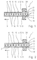
- a device 1 for transporting lumpy product 2 with a circulating transport 3 two drives 4, 5 for the circulation of the Transport device 3, and with walls 6 arranged transversely to the transport direction 9, 7, there is a space 8 between two walls 6, 7 arranged one behind the other a lumpy product 2 recessed ( Figure 1).
- the transport device 3 consists of two separate chain spars 10, 11 arranged parallel to each other, which in clocked manner with transport breaks.
- the walls 6 of the Chain spar 10 protrude into the walls 7 of the chain spar 11 such that a alternating row of parallel to one another and transverse to the transport device 9 aligned walls 6.7 is present.
- the drives 4, 5 are each for one Orbital movement of a chain spar 10, 11 is provided.
- the drives 4, 5 are Servomotors 12, 13.
- the drive 4 for the orbital movement of the chain spar 10 is at the same time a drive 14 for parallel adjustment of the walls 6, 7.
- the drive 4 for parallel adjustment of the walls 6, 7 is by means of a control device 38 with respect its speed controlled so that it reduces the distance between the Walls 6, 7 in empty rooms 8 rotate faster than that for a short period of time Drive 5 so that the chain spar 10 makes a parallel displacement in the transport direction 9 experienced against the chain spar 11.
- the device 1 can be narrower Transport the lumpy product 2 tightly between the walls 6, 7.
- the Chain bars 10, 11, the walls 6, 7 are slightly further apart ( Figure 2), so that an easier insertion of the product 2 in a room 8 or easier removal of product 2 can be done from a room 8.
- control device 38 controls drive 4 as a function of Operating state, d. H. of the clock sequences.
- the drives 4, 5 are electronic to each other synchronized.
- the chain bars 10, 11 are identical.
- a chain spar 10, 11 exists in each case essentially from a lateral boundary 15, 16 on which the walls 6, 7 are attached equidistantly.
- Only the fixed drive 4 moves via its gear 17 the chain spar 10 relative to the chain spar 11 and moves the chain spar 10 uniformly around outside of a displacement process.
- the other drive 5 only moves the chain spar 11 outside of a space change period the transmission 18 with the same rotational speed as the chain spar 10. Zur Increasing the distance between the walls 6, 7 rotates the drive 4 for one corresponding time period slower than the drive 5, so that the chain spar 10 a Parallel displacement against the transport direction 9 with respect to the chain spar 11 experiences.
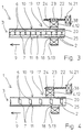
- a drive 4 acts for the Orbital movement of a chain spar 10 via a gear 17 on one Parallel section 19 of the chain spar 10.
- the drive 4 together with the gear 17 parallel to the direction of movement (transport direction 9) of the cooperating with the gear 17 Part 20 of the chain spar 10 by means of a drive 14 for parallel Adjustment of the walls 6, 7 slidable.
- the drive 14 is a stationary servo motor 21 by a control device 38 analogous to the previous embodiment is controlled.
- the drive 14 is via a spindle 22 with the drive 4 for the Orbital movement connected and can move the drive 4.
- Of the Spindle body 23 is rigidly connected to the drive 4 via a connection 24.
- the drives 4, 5 are each on one Deflection wheel 26 of a revolving chain spar 10, 11 arranged and drive the Deflection wheels 26 axially.
- the drive 4 for the circular movement of the chain spar 10 is also a drive 14 for adjusting the walls 6, 7 to each other.
- a Adjustment is realized such that the drive 14 through the function of Control device 38 stopped at a time delay to drive 5 when the cycle stopped becomes.
- the chain spar 10 is complete its drive 4 from a drive 14 for parallel adjustment of the walls 6, 7 slidable.
- the drive 14 is part of a device 27 for moving the Chain spar 10 parallel to the transport direction 9.
- the device 27 has one Rack 28, which is connected to the axes 29 of the planet gears 26, and on which the stationary drive 14 acts with its gear 30.
- the second chain spar 11 is perpendicular to the direction of movement of the chain spar in order to change the The distance between the chain spars 10, 11 and thus the spaces 8 in this direction a device 31 for displacement.
- the device 31 for Moving essentially consists of the drives 32, 33, each of which has a Gear 34, 35 by means of a rack 36, 37 on an axis 29 of a deflection wheel 26 act.
- the drives 32, 33 are operated and adjusted synchronously with one another thus the distance between the chain spars 10, 11 according to the operating state.
- Three Control devices 38 provide an increase in space both in parallel and perpendicular to the direction of transport 9.
Landscapes
- Engineering & Computer Science (AREA)
- Mechanical Engineering (AREA)
- Auxiliary Devices For And Details Of Packaging Control (AREA)
- Control Of Conveyors (AREA)
- Special Conveying (AREA)
Applications Claiming Priority (2)
| Application Number | Priority Date | Filing Date | Title |
|---|---|---|---|
| DE19813120 | 1998-03-25 | ||
| DE19813120A DE19813120A1 (de) | 1998-01-09 | 1998-03-25 | Vorrichtung und Verfahren zum Transportieren von stückigem Produkt |
Publications (3)
| Publication Number | Publication Date |
|---|---|
| EP0945372A2 true EP0945372A2 (fr) | 1999-09-29 |
| EP0945372A3 EP0945372A3 (fr) | 2000-09-06 |
| EP0945372B1 EP0945372B1 (fr) | 2003-05-28 |
Family
ID=7862267
Family Applications (1)
| Application Number | Title | Priority Date | Filing Date |
|---|---|---|---|
| EP19990105607 Expired - Lifetime EP0945372B1 (fr) | 1998-03-25 | 1999-03-19 | Dispositif et procédé pour transporter des articles |
Country Status (2)
| Country | Link |
|---|---|
| EP (1) | EP0945372B1 (fr) |
| ES (1) | ES2199497T3 (fr) |
Cited By (1)
| Publication number | Priority date | Publication date | Assignee | Title |
|---|---|---|---|---|
| EP1145995A1 (fr) * | 2000-03-01 | 2001-10-17 | Shikoku Kakoki Co., Ltd. | Convoyeur |
Family Cites Families (4)
| Publication number | Priority date | Publication date | Assignee | Title |
|---|---|---|---|---|
| AU8158682A (en) * | 1981-03-17 | 1982-09-23 | Hoehn, J.W. | Conveyor |
| JPS6052407A (ja) * | 1983-09-01 | 1985-03-25 | Shibuya Mach Kk | チエ−ンコンベアの位相調整装置 |
| IT1248234B (it) * | 1991-06-14 | 1995-01-05 | Gd Spa | Dispositivo per la ricezione ed il trasferimento di prodotti o pile di prodotti sostanzialmente parallelepipedi ad un successivo convogliatore. |
| JPH0826437A (ja) * | 1994-07-11 | 1996-01-30 | Fuji Photo Film Co Ltd | ワーク移送方法及び移送装置 |
-
1999
- 1999-03-19 EP EP19990105607 patent/EP0945372B1/fr not_active Expired - Lifetime
- 1999-03-19 ES ES99105607T patent/ES2199497T3/es not_active Expired - Lifetime
Cited By (2)
| Publication number | Priority date | Publication date | Assignee | Title |
|---|---|---|---|---|
| EP1145995A1 (fr) * | 2000-03-01 | 2001-10-17 | Shikoku Kakoki Co., Ltd. | Convoyeur |
| US6497320B2 (en) | 2000-03-01 | 2002-12-24 | Shikoku Kakoki Co., Ltd. | Conveyor |
Also Published As
| Publication number | Publication date |
|---|---|
| ES2199497T3 (es) | 2004-02-16 |
| EP0945372A3 (fr) | 2000-09-06 |
| EP0945372B1 (fr) | 2003-05-28 |
Similar Documents
| Publication | Publication Date | Title |
|---|---|---|
| DE69220206T2 (de) | Querheissversiegelungseinrichtung in einer beutelherstellungsmaschine | |
| EP1784350B1 (fr) | Dispositif de groupage de marchandises de detail | |
| EP3034415B1 (fr) | Procédé de transfert de produit d'emballage dans des récipients et de transport des récipients remplis | |
| EP3334669B1 (fr) | Dispositif de transport et procédé de transport employant un tel dispositif de transport | |
| EP3034414B1 (fr) | Procédé de transfert de produit d'emballage dans des récipients et de transport des récipients remplis | |
| EP1268319B1 (fr) | Dispositif convoyeur equipe de supports de packs | |
| CH418956A (de) | Maschine zum Kartonieren von Füllgut aller Art | |
| EP2826735B1 (fr) | Section ajustable de stockage tampon d'un dispositif de convoyage et procédé de stockage intermédiaire d'articles | |
| EP2035283A1 (fr) | Dispositif de traitement de structures tubulaires souples présentant au moins une ouverture | |
| EP3150521B1 (fr) | Dispositif de groupement d'articles et procede de changement de format d'un tel dispositif | |
| DE102008007768B4 (de) | Vorrichtung zum Weiterbewegen von Stückgut | |
| EP1902980A1 (fr) | Dispositif de déplacement en avant réversible destiné au déplacement linéaire par avancement vers l'avant de piles de marchandises par une section de transport | |
| DE3819348C1 (fr) | ||
| EP3366614B1 (fr) | Unité de chaînes d'alimentation | |
| EP2974970A1 (fr) | Dispositif de poussée destiné au remplissage de matériaux d'emballage à l'aide d'emballages transparents | |
| DE3715838C2 (fr) | ||
| EP1053066B1 (fr) | Dispositif de transport | |
| EP2154073B1 (fr) | Procédé et dispositif de remplissage cadencé d'une multitude de récipients | |
| DE3702954A1 (de) | Gruppiereinrichtung zur bildung von behaeltergruppen | |
| DE102013102029A1 (de) | Verstellportal, schrumpfvorrichtung mit einstellbaren schachtwänden und verfahren zur einstellung von schachtwänden | |
| EP0945372B1 (fr) | Dispositif et procédé pour transporter des articles | |
| DE60319892T2 (de) | Artikelpositioniermaschine | |
| DE19813120A1 (de) | Vorrichtung und Verfahren zum Transportieren von stückigem Produkt | |
| DE19803297A1 (de) | Vorrichtung zum Transportieren von stückigem Produkt | |
| EP0558920B1 (fr) | Transporteur à chaîne |
Legal Events
| Date | Code | Title | Description |
|---|---|---|---|
| PUAI | Public reference made under article 153(3) epc to a published international application that has entered the european phase |
Free format text: ORIGINAL CODE: 0009012 |
|
| 17P | Request for examination filed |
Effective date: 19990419 |
|
| AK | Designated contracting states |
Kind code of ref document: A2 Designated state(s): BE DE ES FR GB IT NL |
|
| AX | Request for extension of the european patent |
Free format text: AL;LT;LV;MK;RO;SI |
|
| PUAL | Search report despatched |
Free format text: ORIGINAL CODE: 0009013 |
|
| AK | Designated contracting states |
Kind code of ref document: A3 Designated state(s): AT BE CH CY DE DK ES FI FR GB GR IE IT LI LU MC NL PT SE |
|
| AX | Request for extension of the european patent |
Free format text: AL;LT;LV;MK;RO;SI |
|
| 17Q | First examination report despatched |
Effective date: 20001123 |
|
| AKX | Designation fees paid |
Free format text: BE DE ES FR GB IT NL |
|
| GRAH | Despatch of communication of intention to grant a patent |
Free format text: ORIGINAL CODE: EPIDOS IGRA |
|
| GRAH | Despatch of communication of intention to grant a patent |
Free format text: ORIGINAL CODE: EPIDOS IGRA |
|
| GRAA | (expected) grant |
Free format text: ORIGINAL CODE: 0009210 |
|
| AK | Designated contracting states |
Designated state(s): BE DE ES FR GB IT NL |
|
| REG | Reference to a national code |
Ref country code: GB Ref legal event code: FG4D Free format text: NOT ENGLISH |
|
| REF | Corresponds to: |
Ref document number: 59905699 Country of ref document: DE Date of ref document: 20030703 Kind code of ref document: P |
|
| GBT | Gb: translation of ep patent filed (gb section 77(6)(a)/1977) | ||
| ET | Fr: translation filed | ||
| REG | Reference to a national code |
Ref country code: ES Ref legal event code: FG2A Ref document number: 2199497 Country of ref document: ES Kind code of ref document: T3 |
|
| PLBE | No opposition filed within time limit |
Free format text: ORIGINAL CODE: 0009261 |
|
| STAA | Information on the status of an ep patent application or granted ep patent |
Free format text: STATUS: NO OPPOSITION FILED WITHIN TIME LIMIT |
|
| 26N | No opposition filed |
Effective date: 20040302 |
|
| PGFP | Annual fee paid to national office [announced via postgrant information from national office to epo] |
Ref country code: IT Payment date: 20060331 Year of fee payment: 8 |
|
| PGFP | Annual fee paid to national office [announced via postgrant information from national office to epo] |
Ref country code: NL Payment date: 20070313 Year of fee payment: 9 |
|
| PGFP | Annual fee paid to national office [announced via postgrant information from national office to epo] |
Ref country code: GB Payment date: 20070322 Year of fee payment: 9 |
|
| PGFP | Annual fee paid to national office [announced via postgrant information from national office to epo] |
Ref country code: ES Payment date: 20070329 Year of fee payment: 9 |
|
| PGFP | Annual fee paid to national office [announced via postgrant information from national office to epo] |
Ref country code: DE Payment date: 20070524 Year of fee payment: 9 |
|
| PGFP | Annual fee paid to national office [announced via postgrant information from national office to epo] |
Ref country code: BE Payment date: 20070419 Year of fee payment: 9 |
|
| PGFP | Annual fee paid to national office [announced via postgrant information from national office to epo] |
Ref country code: FR Payment date: 20070319 Year of fee payment: 9 |
|
| BERE | Be: lapsed |
Owner name: *ROVEMA VERPACKUNGSMASCHINEN G.M.B.H. Effective date: 20080331 |
|
| GBPC | Gb: european patent ceased through non-payment of renewal fee |
Effective date: 20080319 |
|
| PG25 | Lapsed in a contracting state [announced via postgrant information from national office to epo] |
Ref country code: NL Free format text: LAPSE BECAUSE OF NON-PAYMENT OF DUE FEES Effective date: 20081001 |
|
| NLV4 | Nl: lapsed or anulled due to non-payment of the annual fee |
Effective date: 20081001 |
|
| REG | Reference to a national code |
Ref country code: FR Ref legal event code: ST Effective date: 20081125 |
|
| PG25 | Lapsed in a contracting state [announced via postgrant information from national office to epo] |
Ref country code: DE Free format text: LAPSE BECAUSE OF NON-PAYMENT OF DUE FEES Effective date: 20081001 |
|
| PG25 | Lapsed in a contracting state [announced via postgrant information from national office to epo] |
Ref country code: BE Free format text: LAPSE BECAUSE OF NON-PAYMENT OF DUE FEES Effective date: 20080331 |
|
| PG25 | Lapsed in a contracting state [announced via postgrant information from national office to epo] |
Ref country code: FR Free format text: LAPSE BECAUSE OF NON-PAYMENT OF DUE FEES Effective date: 20080331 |
|
| REG | Reference to a national code |
Ref country code: ES Ref legal event code: FD2A Effective date: 20080322 |
|
| PG25 | Lapsed in a contracting state [announced via postgrant information from national office to epo] |
Ref country code: GB Free format text: LAPSE BECAUSE OF NON-PAYMENT OF DUE FEES Effective date: 20080319 |
|
| PG25 | Lapsed in a contracting state [announced via postgrant information from national office to epo] |
Ref country code: ES Free format text: LAPSE BECAUSE OF NON-PAYMENT OF DUE FEES Effective date: 20080322 |
|
| PG25 | Lapsed in a contracting state [announced via postgrant information from national office to epo] |
Ref country code: IT Free format text: LAPSE BECAUSE OF NON-PAYMENT OF DUE FEES Effective date: 20070319 |