EP0945373A2 - Dispositif de transfert de bois - Google Patents
Dispositif de transfert de bois Download PDFInfo
- Publication number
- EP0945373A2 EP0945373A2 EP99105920A EP99105920A EP0945373A2 EP 0945373 A2 EP0945373 A2 EP 0945373A2 EP 99105920 A EP99105920 A EP 99105920A EP 99105920 A EP99105920 A EP 99105920A EP 0945373 A2 EP0945373 A2 EP 0945373A2
- Authority
- EP
- European Patent Office
- Prior art keywords
- transfer device
- steps
- stage
- stages
- level
- Prior art date
- Legal status (The legal status is an assumption and is not a legal conclusion. Google has not performed a legal analysis and makes no representation as to the accuracy of the status listed.)
- Withdrawn
Links
- 230000001360 synchronised effect Effects 0.000 claims description 2
- 238000000926 separation method Methods 0.000 description 7
- 239000002023 wood Substances 0.000 description 5
- 238000011144 upstream manufacturing Methods 0.000 description 4
- 239000012634 fragment Substances 0.000 description 3
- 238000010521 absorption reaction Methods 0.000 description 1
- 230000015572 biosynthetic process Effects 0.000 description 1
- 239000011435 rock Substances 0.000 description 1
- 238000007789 sealing Methods 0.000 description 1
Images


Classifications
-
- B—PERFORMING OPERATIONS; TRANSPORTING
- B65—CONVEYING; PACKING; STORING; HANDLING THIN OR FILAMENTARY MATERIAL
- B65G—TRANSPORT OR STORAGE DEVICES, e.g. CONVEYORS FOR LOADING OR TIPPING, SHOP CONVEYOR SYSTEMS OR PNEUMATIC TUBE CONVEYORS
- B65G25/00—Conveyors comprising a cyclically-moving, e.g. reciprocating, carrier or impeller which is disengaged from the load during the return part of its movement
- B65G25/04—Conveyors comprising a cyclically-moving, e.g. reciprocating, carrier or impeller which is disengaged from the load during the return part of its movement the carrier or impeller having identical forward and return paths of movement, e.g. reciprocating conveyors
- B65G25/08—Conveyors comprising a cyclically-moving, e.g. reciprocating, carrier or impeller which is disengaged from the load during the return part of its movement the carrier or impeller having identical forward and return paths of movement, e.g. reciprocating conveyors having impellers, e.g. pushers
Definitions
- the invention relates to a transfer device for transport of logs fed transversely to the conveying direction onto a discharge device, in which a plurality of parallel to each other and arranged inclined to the vertical, against each other sealed stages, each relative to a neighboring stage so cyclically movable in the direction of inclination are trained that in a takeover position of a stage the next level in the conveying direction above the level of the previous one Level lies and that the next level in its takeover position at or below the level of the previous level lies.
- Separation stages with step shifters are also known, in which immovable plate-shaped middle pieces of stepped, movable edge pieces are limited.
- the step-shaped movable edge pieces act with also stepped immovable edge pieces for the purpose of separation or group formation together. Even with very small distances between the edge pieces it happens again and again that fragments or rock pieces that are too short on the rigid middle section and thus block the steps so that the separation or Grouping of the subsequent strains is no longer possible.
- the invention is based on the object, a To create transfer device of the type mentioned that high separation performance with large transport capacity enables.
- this object is achieved in a transfer device of the type mentioned in that solved at the handover end stages with reduced depth to the discharge device are, their drive to carry out a corresponding shorter cycle is formed.
- Frequency of step movements becomes a good transport capacity provided while using stages for singling a smaller depth and preferably also with a smaller one Are formed height, which thus have a lower mass and therefore with a shorter cycle, i.e. a higher one Frequency that can be driven. It is particularly advantageous it is when the levels of different depths by at least a fixed stage are separated.
- Steps and the sealing of the steps moving relative to each other are also residual and broken wood pieces without problems over the Transfer device transported and can not by tilting or jamming lead to blockages.
- a very energy-saving realization of the drive of the steps succeeds if two adjacent stages are achieved by one drive are driven in opposite directions, so that the two stages are mutually effective as counterweights.
- By the downward movement of a level becomes recovered energy thereby brought into the upward movement of the neighboring stage.
- This is particularly easy if the drive for Use of a printing medium is designed, in particular the Drive is a hydraulic drive.
- the arrangement of the stages according to the invention can essentially for one horizontal transportation. Prefers it will generally be when through the transfer device also a height difference is coped with. This can be done by a middle position of a level higher in the direction of conveyance is a middle position of a previous level, regardless of whether only one or both of these stages can be moved are trained.
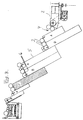
- Figure 1 leaves a feed conveyor driven by a motor 1 2 recognize, lying across the long timber 3 transversely to the transport direction is promoted.
- the log 3 falls into a drop room 4, on which is sealed an obliquely arranged perpendicular to the Stage A connects that in the direction of inclination stage A is driven up and down. Closes at level A.
- stage B following in the conveying direction which is parallel to the previous stage A and, like stage A, a density over the entire width of the transfer device and has sealed side wall 5.
- the stage is in the position shown in FIG B at its upper reversal point and in the conveying direction behind it Level A located at its lower reversal point. Swearing Contact surfaces 6 of the two stages B, A with each other, so that in this position is transferred to level A.
- the of amount transferred to level A in this situation is limited by the depth of level A in that the in the direction of conveyance following stage B also in its upper Reversal point is located and the side wall 5 of stage B the recording room limited to the top 6 of stage A.
- stage B In the upper reversal point of stage B, its surface is aligned 6 with the surface 6 of a fixed step F and one itself adjoining stage A, but its depth is only half as much is as large as the depth of stages A, B upstream in the conveying direction from the fixed level F, the depth of which is depth corresponds to the upstream stages A, B. It is therefore can be seen that the intake for stage A, the downstream is arranged by the fixed stage F through which limited depth of this level is limited.
- One at this Stage A subsequent stage B also with a reduced one
- the transfer to a discharge device 7 ensures the depth is designed as a longitudinal conveyor for the long timber 3.
- FIG. 2 illustrates that the step adjacent to the discharge area 4 A a log length corresponding to its depth during the upward stroke transported upwards, while the following in the conveying direction Level B that of the subsequent level A in the position of Figure 1 due to the depth of the steps not taken long log again transported downwards.
- the fixed level F acts as a storage for the subsequent stages a, b with a smaller depth.
- Figures 2 and 3 illustrate that with the same initial situation according to Figure 1 the downstream of the fixed Stage F arranged stages A, B with less depth their stroke cycle exercise at a higher frequency than that upstream from the fixed stage F arranged stages A, B with the greater depth. In this way, the throughput should be all the steps are about the same, so that the logs are stowed 3 is avoided within the transfer device.
- the Width of the steps 3.50 m, the depth of the steps A, B is upstream of the fixed step F 600 mm and downstream 300 mm. Stages A, B are each 1 m for the wide steps A, B and 0.5 m for the narrow steps A, B.
- the number of stages used is free selectable according to the circumstances. It results in particular from the width of the transfer route, the size of the desired separation and from what can be overcome by the transfer conveyor Height difference.
- the inclination of levels A, B can be according to the usual criteria (to distance to be overcome, height to be overcome, desired degree of separation) be optimized. It makes sense to go through the stroke direction of stages A, B included with the vertical Angle between 10 and 50 °, preferably it is about 30 °, so that the direction of movement with the horizontal one Includes an angle of approximately 60 °.
Landscapes
- Engineering & Computer Science (AREA)
- Mechanical Engineering (AREA)
- Attitude Control For Articles On Conveyors (AREA)
- Feeding Of Articles To Conveyors (AREA)
- Special Conveying (AREA)
Applications Claiming Priority (2)
| Application Number | Priority Date | Filing Date | Title |
|---|---|---|---|
| DE19813040 | 1998-03-25 | ||
| DE1998113040 DE19813040A1 (de) | 1998-03-25 | 1998-03-25 | Übergabevorrichtung zum Transport von Langholz |
Publications (2)
| Publication Number | Publication Date |
|---|---|
| EP0945373A2 true EP0945373A2 (fr) | 1999-09-29 |
| EP0945373A3 EP0945373A3 (fr) | 2000-05-03 |
Family
ID=7862214
Family Applications (1)
| Application Number | Title | Priority Date | Filing Date |
|---|---|---|---|
| EP99105920A Withdrawn EP0945373A3 (fr) | 1998-03-25 | 1999-03-24 | Dispositif de transfert de bois |
Country Status (2)
| Country | Link |
|---|---|
| EP (1) | EP0945373A3 (fr) |
| DE (1) | DE19813040A1 (fr) |
Cited By (2)
| Publication number | Priority date | Publication date | Assignee | Title |
|---|---|---|---|---|
| EP2573012A1 (fr) * | 2011-09-26 | 2013-03-27 | Rowa Automatisierungssysteme GmbH | Dispositif et procédé pour séparer des objets à stocker dans un entrepôt automatisé |
| US9352909B2 (en) * | 2014-05-13 | 2016-05-31 | Usnr, Llc | Workpiece singulator with adjustable stair depth |
Citations (1)
| Publication number | Priority date | Publication date | Assignee | Title |
|---|---|---|---|---|
| US3524532A (en) | 1968-09-17 | 1970-08-18 | Can Eng Holdings Ltd | Elevator structure having chain driven reciprocating plates |
Family Cites Families (5)
| Publication number | Priority date | Publication date | Assignee | Title |
|---|---|---|---|---|
| DE1159849B (de) * | 1961-02-20 | 1963-12-19 | Heinz Nienstedt | Einrichtung zum Vereinzeln von Holz, insbesondere rohem Rundholz |
| WO1982001179A1 (fr) * | 1980-10-03 | 1982-04-15 | Crawford L | Dispositif d'alimentation a secousses pour distribuer des articles |
| CH663404A5 (en) * | 1984-05-21 | 1987-12-15 | Creaxa Ag | Method for the conveying of mass parts and apparatus for carrying out the method |
| FI103029B1 (fi) * | 1992-10-06 | 1999-04-15 | Taehkae Ab Oy | Käyttölaite pitkänomaisten puutavarakappaleiden poikittaissyöttölaitteeseen |
| DE4434146C2 (de) * | 1993-12-24 | 1996-01-25 | Peter Schindler | Fördergerät mit Schiebern für Werkstücke |
-
1998
- 1998-03-25 DE DE1998113040 patent/DE19813040A1/de not_active Withdrawn
-
1999
- 1999-03-24 EP EP99105920A patent/EP0945373A3/fr not_active Withdrawn
Patent Citations (1)
| Publication number | Priority date | Publication date | Assignee | Title |
|---|---|---|---|---|
| US3524532A (en) | 1968-09-17 | 1970-08-18 | Can Eng Holdings Ltd | Elevator structure having chain driven reciprocating plates |
Cited By (8)
| Publication number | Priority date | Publication date | Assignee | Title |
|---|---|---|---|---|
| EP2573012A1 (fr) * | 2011-09-26 | 2013-03-27 | Rowa Automatisierungssysteme GmbH | Dispositif et procédé pour séparer des objets à stocker dans un entrepôt automatisé |
| WO2013045401A1 (fr) * | 2011-09-26 | 2013-04-04 | Rowa Automatisierungssysteme Gmbh | Dispositif et procédé de séparation de marchandises de détail à stocker dans un entrepôt automatisé |
| CN103826996A (zh) * | 2011-09-26 | 2014-05-28 | 康尔富盛德国326有限公司 | 将存入自动化仓库的计件货物分离的装置和方法 |
| US9073697B2 (en) | 2011-09-26 | 2015-07-07 | Carefusion Germany 326 Gmbh | Apparatus and method for separation of piece goods to be placed in storage in an automated storage unit |
| CN103826996B (zh) * | 2011-09-26 | 2016-06-08 | 康尔富盛德国326有限公司 | 将存入自动化仓库的计件货物分离的装置和方法 |
| US9561908B2 (en) | 2011-09-26 | 2017-02-07 | Carefusion Germany 326 Gmbh | Apparatus and method for separation of piece goods to be placed in storage in an automated storage unit |
| US9352909B2 (en) * | 2014-05-13 | 2016-05-31 | Usnr, Llc | Workpiece singulator with adjustable stair depth |
| US10421615B2 (en) * | 2014-05-13 | 2019-09-24 | Usnr, Llc | Workpiece singulator with adjustable stair depth |
Also Published As
| Publication number | Publication date |
|---|---|
| EP0945373A3 (fr) | 2000-05-03 |
| DE19813040A1 (de) | 1999-10-07 |
Similar Documents
| Publication | Publication Date | Title |
|---|---|---|
| EP0230612B1 (fr) | Gratteur latéral pour une halde de matière en vrac | |
| DE69500305T2 (de) | Stapel-, Trennungs- und Abführungsstation für blattförmiges Gut, das von einer Verarbeitungsmaschine abgegeben wird | |
| DE69206614T2 (de) | Trenngitter. | |
| EP4001179A1 (fr) | Élévateur pour un dispositif de séchage de matières et dispositif de séchage de matières | |
| EP0065027B1 (fr) | Dispositif de déchargement de presse | |
| DE2259273C2 (de) | Vorrichtung zum Ausschleusen von Stückgut aus einer Rollenbahn | |
| CH670809A5 (fr) | ||
| EP0945373A2 (fr) | Dispositif de transfert de bois | |
| EP0038432B1 (fr) | Dispositif de désempilage de piles, notamment constituées de pièces de bois allongées | |
| DE3302046A1 (de) | Verfahren zum stapeln oder entstapeln von langmaterial und stapel- bzw. entstapelvorrichtung | |
| EP0659669B1 (fr) | Dispositif pour introduire des enveloppes empilées sur leur chant dans un bac | |
| DE2233880A1 (de) | Abtrennvorrichtung | |
| EP0657259A1 (fr) | Dispositif de coupe pour boudin d'argile | |
| DE3926966C2 (fr) | ||
| DE4420512A1 (de) | Sortier- und Stapelanlage für Plattenaufteileinrichtungen | |
| DE3242484C1 (de) | Transportvorrichtung fuer laengliche Werkstuecke | |
| DE2618568A1 (de) | Zufuehr-vorrichtung fuer materialstaebe | |
| DE20214860U1 (de) | Bandförderer mit Ausschleuseinrichtung | |
| DE1966372C3 (de) | Einrichtung zum Überführen von Lastenträgern für Schleppkreisförderer von einer ersten Antriebsschiene auf eine zweite. Ausscheidung aus: 1944345 | |
| DE69600436T2 (de) | Schale zur Förderung von beliebigen Produkten | |
| DE4121517C1 (fr) | ||
| DE3219872C2 (de) | Vorrichtung zum geräuscharmen Ablegen von Stangenprofilen, insbesondere runden Stäben und Rohren | |
| EP0457720B1 (fr) | Dispositif d'alimentation pour une machine pour l'assemblage de feuilles de placage en bande continue | |
| AT405508B (de) | Sortier- und stapeleinrichtung für plattenaufteilanlagen | |
| AT380187B (de) | Verfahren und vorrichtung zum sortierten sammeln von schnittholz, insbesondere nach der schnittholzbreite |
Legal Events
| Date | Code | Title | Description |
|---|---|---|---|
| PUAI | Public reference made under article 153(3) epc to a published international application that has entered the european phase |
Free format text: ORIGINAL CODE: 0009012 |
|
| AK | Designated contracting states |
Kind code of ref document: A2 Designated state(s): AT BE CH CY DE DK ES FI FR GB GR IE IT LI LU MC NL PT SE |
|
| AX | Request for extension of the european patent |
Free format text: AL;LT;LV;MK;RO;SI |
|
| PUAL | Search report despatched |
Free format text: ORIGINAL CODE: 0009013 |
|
| AK | Designated contracting states |
Kind code of ref document: A3 Designated state(s): AT BE CH CY DE DK ES FI FR GB GR IE IT LI LU MC NL PT SE |
|
| AX | Request for extension of the european patent |
Free format text: AL;LT;LV;MK;RO;SI |
|
| AKX | Designation fees paid | ||
| REG | Reference to a national code |
Ref country code: DE Ref legal event code: 8566 |
|
| STAA | Information on the status of an ep patent application or granted ep patent |
Free format text: STATUS: THE APPLICATION IS DEEMED TO BE WITHDRAWN |
|
| 18D | Application deemed to be withdrawn |
Effective date: 20001104 |