EP0945583A2 - Scharniersystem für Schutzgitter, Schlagläden o.dgl. Schutzeinrichtungen an Fenstern und Türen im Aussenbereich von Gebäuden o.dgl. - Google Patents
Scharniersystem für Schutzgitter, Schlagläden o.dgl. Schutzeinrichtungen an Fenstern und Türen im Aussenbereich von Gebäuden o.dgl. Download PDFInfo
- Publication number
- EP0945583A2 EP0945583A2 EP98121893A EP98121893A EP0945583A2 EP 0945583 A2 EP0945583 A2 EP 0945583A2 EP 98121893 A EP98121893 A EP 98121893A EP 98121893 A EP98121893 A EP 98121893A EP 0945583 A2 EP0945583 A2 EP 0945583A2
- Authority
- EP
- European Patent Office
- Prior art keywords
- hinge
- protective
- same
- frame
- cylindrical core
- Prior art date
- Legal status (The legal status is an assumption and is not a legal conclusion. Google has not performed a legal analysis and makes no representation as to the accuracy of the status listed.)
- Withdrawn
Links
- 230000000149 penetrating effect Effects 0.000 claims abstract description 3
- 230000001681 protective effect Effects 0.000 claims description 57
- 230000004224 protection Effects 0.000 claims description 3
- 238000005553 drilling Methods 0.000 description 1
- 238000003780 insertion Methods 0.000 description 1
- 230000037431 insertion Effects 0.000 description 1
Images

Classifications
-
- E—FIXED CONSTRUCTIONS
- E05—LOCKS; KEYS; WINDOW OR DOOR FITTINGS; SAFES
- E05D—HINGES OR SUSPENSION DEVICES FOR DOORS, WINDOWS OR WINGS
- E05D11/00—Additional features or accessories of hinges
- E05D11/0018—Anti-tamper devices
-
- E—FIXED CONSTRUCTIONS
- E05—LOCKS; KEYS; WINDOW OR DOOR FITTINGS; SAFES
- E05F—DEVICES FOR MOVING WINGS INTO OPEN OR CLOSED POSITION; CHECKS FOR WINGS; WING FITTINGS NOT OTHERWISE PROVIDED FOR, CONCERNED WITH THE FUNCTIONING OF THE WING
- E05F11/00—Man-operated mechanisms for operating wings, including those which also operate the fastening
- E05F11/36—Man-operated mechanisms for operating wings, including those which also operate the fastening specially designed for passing through a wall
-
- E—FIXED CONSTRUCTIONS
- E05—LOCKS; KEYS; WINDOW OR DOOR FITTINGS; SAFES
- E05Y—INDEXING SCHEME ASSOCIATED WITH SUBCLASSES E05D AND E05F, RELATING TO CONSTRUCTION ELEMENTS, ELECTRIC CONTROL, POWER SUPPLY, POWER SIGNAL OR TRANSMISSION, USER INTERFACES, MOUNTING OR COUPLING, DETAILS, ACCESSORIES, AUXILIARY OPERATIONS NOT OTHERWISE PROVIDED FOR, APPLICATION THEREOF
- E05Y2800/00—Details, accessories and auxiliary operations not otherwise provided for
- E05Y2800/26—Form or shape
-
- E—FIXED CONSTRUCTIONS
- E05—LOCKS; KEYS; WINDOW OR DOOR FITTINGS; SAFES
- E05Y—INDEXING SCHEME ASSOCIATED WITH SUBCLASSES E05D AND E05F, RELATING TO CONSTRUCTION ELEMENTS, ELECTRIC CONTROL, POWER SUPPLY, POWER SIGNAL OR TRANSMISSION, USER INTERFACES, MOUNTING OR COUPLING, DETAILS, ACCESSORIES, AUXILIARY OPERATIONS NOT OTHERWISE PROVIDED FOR, APPLICATION THEREOF
- E05Y2900/00—Application of doors, windows, wings or fittings thereof
- E05Y2900/10—Application of doors, windows, wings or fittings thereof for buildings or parts thereof
- E05Y2900/13—Type of wing
- E05Y2900/132—Doors
-
- E—FIXED CONSTRUCTIONS
- E05—LOCKS; KEYS; WINDOW OR DOOR FITTINGS; SAFES
- E05Y—INDEXING SCHEME ASSOCIATED WITH SUBCLASSES E05D AND E05F, RELATING TO CONSTRUCTION ELEMENTS, ELECTRIC CONTROL, POWER SUPPLY, POWER SIGNAL OR TRANSMISSION, USER INTERFACES, MOUNTING OR COUPLING, DETAILS, ACCESSORIES, AUXILIARY OPERATIONS NOT OTHERWISE PROVIDED FOR, APPLICATION THEREOF
- E05Y2900/00—Application of doors, windows, wings or fittings thereof
- E05Y2900/10—Application of doors, windows, wings or fittings thereof for buildings or parts thereof
- E05Y2900/13—Type of wing
- E05Y2900/148—Windows
Definitions
- the invention relates to a hinge system for Protective grilles, shutters or the like.
- Protective devices on windows and doors in the exterior of buildings or the like consisting of an upper and a lower hinge, each made up of a hinge base that can be attached to or in the masonry and a hinge top that is attached to the respective Protective grille, shutter or the like.
- Protective device or its Frame is attachable.
- a hinge is known that on a vertically arranged hinge lower part Has pivot around which the hinge top with a Longitudinal bore is rotatable in the same.
- the hinge lower part has a wall anchor extending radially to the bearing journal that can be used in the masonry of buildings.
- the upper hinge part consists of a socket on the outside A circumference radially to the longitudinal center bore of the The upper hinge part of the threaded bolt is provided, in a corresponding threaded hole in the protective grille, Blow store or the like Protective device or frame can be used.
- the wall anchor of the hinge base and the Threaded bolts of the upper hinge part are like this to each other arranged that the top hinge with its Longitudinal center hole or the like after insertion in the protective grille. or in the frame and the rotation of the hinge upper part 90 ° a drilling jig for making the hole for the Wall anchor forms. There is also an anti-lift device intended.
- the invention is therefore based on the object Hinge system for protective grilles, blow shutters or the like.
- additional Locking devices such as padlocks or the like.
- waived can be, and with which the protective grille, blow shutters or the like.
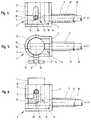
- the hinge system shown in the figures for Protective grilles, shutters or the like essentially consists of a lower hinge 1 and an upper hinge 2. Both hinges 1, 2 sit down each together from a hinge lower part 3, which on or in Masonry is attachable and an upper hinge part 4 that the respective protective grille, blow shutter or the like. Protective device or its frame 5 can be attached.
- the lower hinge part 3 of each of the hinges 1, 2 is made from a tubular housing 6 with a radial to the same extending wall anchor 7.
- the housing 6 In the housing 6 is in essentially cylindrical core 8 of the hinge upper part 4 rotatably supported and held.
- On the hinge upper part 4 or on the cylindrical core 8 of the same is on the outer circumference radially extending threaded bolt 9 is provided, which in a corresponding threaded hole 10 of the protective grille, Blow store or the like Protective device or frame 5 can be used.
- one of the two hinges 1, 2 has a rotating device 11 on that a rotation of the hinge top 4 with the Protective grille, shutter or the like.
- Turning device 11 will be discussed in more detail later.
- anti-lift device 12 on both hinges 1, 2 intended.
- This anti-lift device 12 essentially exists from the with the protective grille, blow shutter or the like.
- Protective device or threaded bolt 9 connected to frame 5, the in a radial slot 13 on the circumference of the housing 6 of the Lower hinge part 3 is guided and in the closed position of the protective grille, blow shutter or the like.
- Protective device or of the frame 5 by a locking device 14 on the other Hinge 2 in an axially parallel slot 15 on End of the radial slot 13 is moved.
- Locking device 14 and the rotating device 11 both provided on the upper hinge 2 and on the lower hinge 1 can be.
- the version of the lower one described here Hinge 1 with rotating device 11 and the upper hinge 2 with locking device 14 is only an example understand.
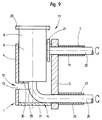
- Both the rotating device 11 and the Locking device 14 can also both one of the Hinges 1, 2 can be assigned, advantageously to the lower (1), which is more accessible from the inside (see Fig. 7 till 9).
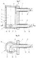
- the locking device 14 on the upper hinge 2 (Fig. 4 to 6) consists essentially of a slide 16 which in a coaxial bore 17 of the wall anchor 7 is mounted and penetrates the same on an inclined plane 18 at the bottom End of the upper hinge part 4 or of the cylindrical core 8 attacks the same and the hinge top 4 or cylindrical core 8 of the same moved so that the protective grid, the blow shop or the like Protective device or the frame 5 in the closed or open position is reached.
- the rotating device 11 (here, for example, at the bottom Hinge 1 (Fig. 1 to 3)) consists of a ring gear 20 or the like at the upper end of the upper hinge part 4 or the core 8 the same.
- the ring gear 20 stands with a pinion 21 or the like at the front end of a in the coaxial bore 17 of the Wall anchor 7 mounted and penetrating the same shaft 22nd engaged.
- 1 to 3 is, for example Taper gear shown. Of course everyone can do that too other teeth can be provided (see also Fig. 7 to 9).
- both the rotating device 11 and the locking device 14 the hinge 1 assigned.
- the rotating device 11 is like that Hinge system according to FIGS. 1 to 3 executed.
- the locking device 14 consists in essentially from an approximately L-shaped rotary lever 25, the in a coaxial bore 26 of a second wall anchor 27 of the Hinge 1 is mounted and penetrates the same.
- the second Wall anchor 27 is opposite the axis of rotation 28 of the Upper hinge part 4 or the cylindrical core 8 of the same laterally offset.
- the short leg 29 of the rotary lever 25 engages on a surface 30 of the lower hinge part 4 or cylindrical core 8 of the same.
- Protective device or frame 5 is the short Leg 29 of the rotary lever 25 flat on the bottom 31 of the Hinge lower part 3 on (Fig. 7 and 8), with closed position, the upper end of the short leg 29 the cylindrical core 8 of the hinge upper part 4 receiving bore 32 abuts (dash-dotted in Fig. 8 shown), somewhat beyond the dead center, i.e. self-locking.
- the design of the upper hinge 2 is as in 4 to 6 shown, the Locking device 14 and the inclined plane 18 on lower end of the hinge upper part 4 or the cylindrical Core 8 is not applicable.
Landscapes
- Engineering & Computer Science (AREA)
- Mechanical Engineering (AREA)
- Hinges (AREA)
- Grates (AREA)
- Wing Frames And Configurations (AREA)
- Building Environments (AREA)
Abstract
Description
- Fig. 1
- eine Seitenansicht eines ersten Ausführungsbeispieles beispielsweise eines unteren Scharniers mit Drehvorrichtung,
- Fig. 2
- die Draufsicht des Scharniers nach Fig. 1,
- Fig. 3
- die Seitenansicht des Scharniers wie Fig. 1, jedoch in angehobener Position,
- Fig. 4
- eine Seitenansicht des ersten Ausführungsbeispieles beispielsweise eines oberen Scharniers mit Verriegelungsvorrichtung,
- Fig. 5
- die Draufsicht des Scharniers nach Fig. 4,
- Fig. 6
- die Seitenansicht des Scharniers wie Fig. 4, jedoch in angehobener Position.
- Fig. 7
- einen Längsschnitt eines zweiten Ausführungsbeispieles beispielsweise durch ein unteres Scharnier mit Drehvorrichtung und Verriegelungsvorrichtung,
- Fig. 8
- einen Schnitt nach der Linie VIII-VIII in Fig. 7 und
- Fig. 9
- den Längsschnitt durch das Scharnier wie Fig. 7, jedoch in angehobener Position.
Claims (8)
- Scharniersystem für Schutzgitter, Schlagläden o.dgl. Schutzeinrichtungen an Fenstern und Türen im Außenbereich von Gebäuden o.dgl., bestehend aus einem unteren und einem oberen Scharnier, die sich jeweils aus einem Scharnierunterteil, das am bzw. im Mauerwerk befestigbar ist, und einem Scharnieroberteil, das an dem jeweiligen Schutzgitter, Schlagladen o.dgl. Schutzeinrichtungen bzw. dessen Rahmen befestigbar ist, zusammensetzt, dadurch gekennzeichnet, daß eines der beiden Scharniere (1, 2) eine Drehvorrichtung (11) aufweist, die ein Drehen des Scharnieroberteils (4) mit Schutzgitter, Schlagladen o.dgl. Schutzeinrichtung bzw. des Rahmens (5) vom Innenbereich von Gebäuden o.dgl. aus ermöglicht, und daß an beiden Scharnieren (1, 2) eine Aushebesicherung und Drehverriegelung (12) vorgesehen ist.
- Scharniersystem nach Anspruch 1, dadurch gekennzeichnet, daß das Scharnierunterteil (3) der Scharniere (1, 2) aus einem rohrartigen Gehäuse (6) mit mindestens einem radial zu demselben verlaufenden Maueranker (7) besteht, wobei in dem Gehäuse (6) ein im wesentlichen zylindrischer Kern (8) des Scharnieroberteils (4) drehbar gelagert und gehalten ist, und daß an dem Scharnieroberteil (4) bzw. dem zylindrischen Kern (8) desselben an seinem äußeren Umfang ein radial zu demselben angeordneter Gewindebolzen (9) vorgesehen ist, der in eine entsprechende Gewindebohrung (10) des Schutzgitters, Schlagladens o.dgl. Schutzeinrichtung bzw. des Rahmens (5) einsetzbar ist.
- Scharniersystem nach Anspruch 1 oder 2, dadurch gekennzeichnet, daß die Drehvorrichtung (11) aus einem Zahnkranz (20) o.dgl. am oberen Ende des Scharnieroberteils (4) bzw. dem Kern (8) desselben gebildet ist, der mit einem Ritzel (21) o.dgl. am vorderen Ende einer in einer koaxialen Bohrung (17) eines der Maueranker (7) gelagerten und denselben durchdringenden Welle (22) in Eingriff steht.
- Scharniersystem nach Anspruch 3, dadurch gekennzeichnet, daß an dem Scharnierunterteil (3) am Grund seines Gehäuses (6) ein vertikal gerichteter Lagerzapfen (23) angeordnet ist, auf dem das Scharnieroberteil (4) bzw. der zylindrische Kern (8) desselben mit einer koaxialen Bohrung (24) gelagert und geführt ist.
- Scharniersystem nach einem der Ansprüche 1 bis 4, dadurch gekennzeichnet, daß die Aushebesicherung und Drehverriegelung (12) im wesentlichen aus dem mit dem Schutzgitter, Schlagladen o.dgl. Schutzeinrichtung bzw. dem Rahmen (5) verbundenen Gewindebolzen (9) besteht, der in einem radialen Schlitz (13) am Umfang des Gehäuses (6) des Scharnierunterteils (3) geführt ist und in geschlossener Stellung des Schutzgitters, Schlagladens o.dgl. Schutzeinrichtung bzw. des Rahmens (5) durch eine Verriegelungsvorrichtung (14) an dem einen Scharnier (1) oder dem anderen Scharnier (2) in einen achsparallel verlaufenden Schlitz (15) am Ende des radialen Schlitzes (13) bewegt wird.
- Scharniersystem nach einem der Ansprüche 1 bis 5, dadurch gekennzeichnet, daß die Verriegelungsvorrichtung (14) im wesentlichen aus einem Schieber (16) besteht, der in einer koaxialen Bohrung (17) des Mauerankers (7) gelagert ist und denselben durchdringt, der an einer schiefen Ebene (18) am unteren Ende des Scharnieroberteils (4) bzw. des zylindrischen Kerns (8) desselben angreift und das Scharnieroberteil (4) bzw. den zylindrischen Kern (8) desselben so bewegt, daß das Schutzgitter, der Schlagladen o.dgl. Schutzeinrichtung bzw. der Rahmen (5) in die geschlossene bzw. geöffnete Stellung gelangt.
- Scharniersystem nach einem der Ansprüche 1 bis 6, dadurch gekennzeichnet, daß sowohl die Drehvorrichtung (11) als auch die Verriegelungsvorrichtung (14) an einem der Scharniere (1, 2) vorgesehen ist.
- Scharniersystem nach einem der Ansprüche 1 bis 5 oder 7, dadurch gekennzeichnet, daß die Verriegelungsvorrichtung (14) im wesentlichen aus einem etwa L-förmig geformten Drehhebel (25) besteht, der in einer koaxialen Bohrung (26) eines zweiten Mauerankers (27) des Scharniers (1) gelagert ist und denselben durchdringt, wobei der zweite Maueranker (27) gegenüber der Drehachse (28) des Scharnieroberteils (4) bzw. des zylindrischen Kerns (8) desselben seitlich versetzt ist und der kurze Schenkel (29) des Drehhebels (25) an einer Fläche (30) am unteren Ende des Scharnieroberteiles (4) bzw. des zylindrischen Kerns (8) desselben angreift und das Scharnieroberteil (4) bzw. den zylindrischen Kern (8) desselben durch Drehen des Drehhebels (25) so bewegt, daß das Schutzgitter, der Schlagladen o.dgl. Schutzeinrichtung bzw. der Rahmen 5 in die geschlossene bzw. geöffnete Stellung gelangt.
Applications Claiming Priority (2)
| Application Number | Priority Date | Filing Date | Title |
|---|---|---|---|
| DE29805214U | 1998-03-23 | ||
| DE29805214U DE29805214U1 (de) | 1998-03-23 | 1998-03-23 | Scharniersystem für Schutzgitter, Schlagläden o.dgl. Schutzeinrichtungen an Fenstern und Türen im Außenbereich von Gebäuden o.dgl. |
Publications (2)
| Publication Number | Publication Date |
|---|---|
| EP0945583A2 true EP0945583A2 (de) | 1999-09-29 |
| EP0945583A3 EP0945583A3 (de) | 2001-03-28 |
Family
ID=8054602
Family Applications (1)
| Application Number | Title | Priority Date | Filing Date |
|---|---|---|---|
| EP98121893A Withdrawn EP0945583A3 (de) | 1998-03-23 | 1998-11-18 | Scharniersystem für Schutzgitter, Schlagläden o.dgl. Schutzeinrichtungen an Fenstern und Türen im Aussenbereich von Gebäuden o.dgl. |
Country Status (2)
| Country | Link |
|---|---|
| EP (1) | EP0945583A3 (de) |
| DE (1) | DE29805214U1 (de) |
Citations (1)
| Publication number | Priority date | Publication date | Assignee | Title |
|---|---|---|---|---|
| DE29720747U1 (de) | 1997-11-22 | 1998-01-08 | Siepe, Gabriele, 59969 Hallenberg | Scharnier für Schutzgitter, Schlagläden o.dgl. Schutzeinrichtungen an Fenstern und Türen im Außenbereich von Gebäuden u.dgl. |
Family Cites Families (6)
| Publication number | Priority date | Publication date | Assignee | Title |
|---|---|---|---|---|
| DE362343C (de) * | 1922-10-26 | Julius Simshaeuser | Fischband-Feststellvorrichtung fuer Fenster, Tueren u. dgl. | |
| DE242508C (de) * | ||||
| DE268962C (de) * | ||||
| FR462517A (fr) * | 1912-09-16 | 1914-01-29 | William Russell Sweet | Charnière et serrure combinées |
| FR2594472A1 (fr) * | 1986-02-19 | 1987-08-21 | Rauner Hans | Penture pour volets de fenetres et de portes |
| ATE128512T1 (de) * | 1992-03-30 | 1995-10-15 | Martin Brun | Vorrichtung zum oeffnen und schliessen eines fensterladens vom innenraum her. |
-
1998
- 1998-03-23 DE DE29805214U patent/DE29805214U1/de not_active Expired - Lifetime
- 1998-11-18 EP EP98121893A patent/EP0945583A3/de not_active Withdrawn
Patent Citations (1)
| Publication number | Priority date | Publication date | Assignee | Title |
|---|---|---|---|---|
| DE29720747U1 (de) | 1997-11-22 | 1998-01-08 | Siepe, Gabriele, 59969 Hallenberg | Scharnier für Schutzgitter, Schlagläden o.dgl. Schutzeinrichtungen an Fenstern und Türen im Außenbereich von Gebäuden u.dgl. |
Also Published As
| Publication number | Publication date |
|---|---|
| DE29805214U1 (de) | 1998-05-20 |
| EP0945583A3 (de) | 2001-03-28 |
Similar Documents
| Publication | Publication Date | Title |
|---|---|---|
| DE102007017453B4 (de) | Drehöffnungsbegrenzungsvorrichtung für einen Flügel eines Fensters oder dergleichen | |
| EP1071857B1 (de) | Einbausicherung und schlüssel für ein sicherheitsschloss | |
| DE4244414C2 (de) | Verschluß für Fenster, Türen u. dgl. | |
| DE19919554C2 (de) | Torverriegelungsvorrichtung | |
| WO2017118626A1 (de) | Verriegelungsvorrichtung als einbruchssicherung für z. b. fenster und türen | |
| DE3515384A1 (de) | Tuerschloss | |
| DE69401143T2 (de) | Schwenktüre | |
| DE19504720A1 (de) | Sicherheitsvorrichtung für Fenster oder Türen zum Verhindern von Einbrüchen | |
| EP0945583A2 (de) | Scharniersystem für Schutzgitter, Schlagläden o.dgl. Schutzeinrichtungen an Fenstern und Türen im Aussenbereich von Gebäuden o.dgl. | |
| DE19628011C5 (de) | Spereinrichtung für die Riegel eine Riegelwerks | |
| DE3010115A1 (de) | Arretierungsvorrichtung fuer vorreiberverschluesse, stangenverschluesse u.dgl. | |
| DE3642253A1 (de) | Abschliessbarer fenstergriff | |
| EP0761920A2 (de) | Fenster/Tür mit Dreh-Kipp-Beschlag | |
| DE9210795U1 (de) | Sicherheitsbeschlag für mit einem Profilschließzylinder versehene Türschlösser | |
| EP0632179B1 (de) | Vorrichtung zur Verriegelung von Fenstern, Türen oder dergleichen | |
| EP1041230A2 (de) | Torverriegelungsvorrichtung, insbesondere für ein Einblatt-Überkopftor | |
| DE29506799U1 (de) | Vorrichtung an einem Türschloß | |
| EP2060710A2 (de) | Schloss | |
| DE4200868A1 (de) | Zusatz-schliesseinrichtung fuer fenster | |
| AT337034B (de) | Zylinderschloss mit einer sicherung gegen unbefugtes offnen | |
| DE29615631U1 (de) | Sicherungseinrichtung | |
| EP1077300A1 (de) | Schloss mit Zylinderschutz | |
| DE9208797U1 (de) | Einsteckschloß mit zusätzlich blockierender Sperreinrichtung für den Schließriegel | |
| DE29521521U1 (de) | Verriegelungseinrichtung | |
| DE102017009348B4 (de) | Fenster- & Türsicherung zur nachträglichen Sicherung für mindestens einen Flügel, eines Fensters oder einer Tür |
Legal Events
| Date | Code | Title | Description |
|---|---|---|---|
| PUAI | Public reference made under article 153(3) epc to a published international application that has entered the european phase |
Free format text: ORIGINAL CODE: 0009012 |
|
| AK | Designated contracting states |
Kind code of ref document: A2 Designated state(s): AT BE CH DE FR IT LI NL |
|
| AX | Request for extension of the european patent |
Free format text: AL;LT;LV;MK;RO;SI |
|
| PUAL | Search report despatched |
Free format text: ORIGINAL CODE: 0009013 |
|
| AK | Designated contracting states |
Kind code of ref document: A3 Designated state(s): AT BE CH CY DE DK ES FI FR GB GR IE IT LI LU MC NL PT SE |
|
| AX | Request for extension of the european patent |
Free format text: AL;LT;LV;MK;RO;SI |
|
| AKX | Designation fees paid |
Free format text: AT BE CH DE FR IT LI NL |
|
| STAA | Information on the status of an ep patent application or granted ep patent |
Free format text: STATUS: THE APPLICATION IS DEEMED TO BE WITHDRAWN |
|
| 18D | Application deemed to be withdrawn |
Effective date: 20010929 |