EP0945592A1 - Machine à piston rotatif - Google Patents
Machine à piston rotatif Download PDFInfo
- Publication number
- EP0945592A1 EP0945592A1 EP98105430A EP98105430A EP0945592A1 EP 0945592 A1 EP0945592 A1 EP 0945592A1 EP 98105430 A EP98105430 A EP 98105430A EP 98105430 A EP98105430 A EP 98105430A EP 0945592 A1 EP0945592 A1 EP 0945592A1
- Authority
- EP
- European Patent Office
- Prior art keywords
- cam
- control means
- rotating body
- cam track
- rotary piston
- Prior art date
- Legal status (The legal status is an assumption and is not a legal conclusion. Google has not performed a legal analysis and makes no representation as to the accuracy of the status listed.)
- Granted
Links
- 238000007789 sealing Methods 0.000 claims abstract description 4
- 238000005096 rolling process Methods 0.000 claims description 30
- 230000005540 biological transmission Effects 0.000 description 2
- 238000002485 combustion reaction Methods 0.000 description 2
- 230000006835 compression Effects 0.000 description 2
- 238000007906 compression Methods 0.000 description 2
- 238000000034 method Methods 0.000 description 2
- 230000001360 synchronised effect Effects 0.000 description 2
- 238000010276 construction Methods 0.000 description 1
- 230000000694 effects Effects 0.000 description 1
- 230000002996 emotional effect Effects 0.000 description 1
- 230000002349 favourable effect Effects 0.000 description 1
- 239000000446 fuel Substances 0.000 description 1
- 238000004519 manufacturing process Methods 0.000 description 1
- 230000001105 regulatory effect Effects 0.000 description 1
- 238000013519 translation Methods 0.000 description 1
- 230000014616 translation Effects 0.000 description 1
Images

Classifications
-
- F—MECHANICAL ENGINEERING; LIGHTING; HEATING; WEAPONS; BLASTING
- F01—MACHINES OR ENGINES IN GENERAL; ENGINE PLANTS IN GENERAL; STEAM ENGINES
- F01C—ROTARY-PISTON OR OSCILLATING-PISTON MACHINES OR ENGINES
- F01C20/00—Control of, monitoring of, or safety arrangements for, machines or engines
- F01C20/10—Control of, monitoring of, or safety arrangements for, machines or engines characterised by changing the positions of the inlet or outlet openings with respect to the working chamber
- F01C20/14—Control of, monitoring of, or safety arrangements for, machines or engines characterised by changing the positions of the inlet or outlet openings with respect to the working chamber using rotating valves
-
- F—MECHANICAL ENGINEERING; LIGHTING; HEATING; WEAPONS; BLASTING
- F01—MACHINES OR ENGINES IN GENERAL; ENGINE PLANTS IN GENERAL; STEAM ENGINES
- F01C—ROTARY-PISTON OR OSCILLATING-PISTON MACHINES OR ENGINES
- F01C1/00—Rotary-piston machines or engines
- F01C1/02—Rotary-piston machines or engines of arcuate-engagement type, i.e. with circular translatory movement of co-operating members, each member having the same number of teeth or tooth-equivalents
- F01C1/063—Rotary-piston machines or engines of arcuate-engagement type, i.e. with circular translatory movement of co-operating members, each member having the same number of teeth or tooth-equivalents with coaxially-mounted members having continuously-changing circumferential spacing between them
- F01C1/067—Rotary-piston machines or engines of arcuate-engagement type, i.e. with circular translatory movement of co-operating members, each member having the same number of teeth or tooth-equivalents with coaxially-mounted members having continuously-changing circumferential spacing between them having cam-and-follower type drive
Definitions
- the invention relates to a rotary piston machine with a housing, with a shaft rotatably mounted in the housing with a Annulus in which two rotating bodies are arranged and inlet and outlet openings for the working medium on its walls are provided, each rotational body radially has outwardly extending sector-shaped wings that two rotating bodies are arranged coaxially and their wings interlock so that one wing of the one Rotation body between two wings of the other rotation body is arranged, two cam track controls being provided through which both bodies of rotation rotate when the shaft rotates Rotations with cyclical changes in the speed of rotation and the distances between the wings of the Execute both rotating bodies and the cam track control each rotational body first cam track control means in Form of first cam rings, second cam track control means in the form of second cam rings and third cam track control means in the form of itself towards both end faces have conically tapered rolling elements that on the roll the first and second cam rings, one of the first and second cam track control means with the shaft and the other of these cam control means with one of the Rotational body non
- a rotary piston machine of the type mentioned at the outset to create one has higher efficiency.
- This measure can be used, for example, for a compressor the outlet pressure can be regulated.
- the time at which after the compressed gas begins to flow out during compression can be changed by adjusting the control segment. Thereby then of course the pressure with which that changes Gas escapes.
- the residual pressure is not correct there relax and his energy back to the rotary lobe machine can give up.
- Another solution is characterized by the fourth, freely rotatable cam control means are provided that the third cam control means two each independently have mutually rotatable rolling elements, the one this rolling element with the first and fourth and the other this rolling element with the fourth and second cam track control means is engaged.
- the fourth cam control means freely rotatable on one Mounted shaft sleeve that surrounds the shaft.
- the device can be designed so that all rolling elements have the same diameter.
- the manufacture is further facilitated in that the construction can be selected so that only the first, second and fourth cam controls asymmetrical Have toothing, while this with the rolling elements is not the case.
- the rolling elements are expediently made of two identical parts composed.
- the rotary lobe machine is expediently with a bearing flange provided with thrust and radial bearings so that all Forces and loads can be absorbed well.
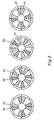
- annular space 1 is a rotary piston machine of the invention shown, which is enclosed by parts of the housing 2 becomes.
- the two interlocking Rotary body which is designed as impellers 3 and 4 are.
- the impeller 3 has the vanes 3a, 3b, 3c and 3d on, while the impeller 4, the vanes 4a, 4b, 4c and 4d. Both impellers are arranged in the middle Shaft 5 driven in a manner to be described.
- 6a-h there are different inlet openings and outlet openings designated in the end wall of the annular space 1.
- This mode of action can be used for both a compressor and can be used for an internal combustion engine. It should only combustion rooms, fuel lines, etc. be provided.
- Fig. 2 are four phases of the work cycle just described shown. After a 90 degree rotation of the two rotating bodies a new work cycle begins.
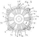
- FIG. 3 is in a similar representation as in FIG. 1st and Figure 2 shows a first embodiment.
- the wings of the rotating body 3, 4 are no longer sealed on the wall of the Housing 2. Between the outer ends of the wings 3a to Rather, 3d, 4a to 4d and the wall of the housing 2 are located still four control segments 7, which in the circumferential direction With the help of gears 8 can be moved. against this Control segments 7 are the ends of the impellers 3, 4 sealing on.
- the control segments 7 are shifted Expediently synchronous, for which not only a synchronous one Can drive the gears 8, but also protrusions, with which the individual tax segments touch. This Control segments can partially those not shown in Fig.
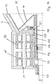
- Fig. 4 shows in section the drive of the impeller 4, in one fragmentary view.
- the impeller 3 is on the in Fig. 4 right side driven by analog drive elements.
- a drive shaft 10 is mounted, with the a first cam ring 11 is firmly connected.
- the impeller 4 is on the other hand connected to a shaft sleeve 12 which the Surrounds shaft 10 and firmly connected to a second cam ring 12 is.
- a third cam ring 13 is by means of a bearing 14 freely rotatably mounted on the shaft sleeve 18.
- Above the cam rings 11, 12 and 13 are two rolling elements 15 and 16 freely rotatable on an axis 17.
- the rolling elements 15 and 16 have teeth that are curved Toothings in the cam rings 11, 12, 13 in engagement are.
- the torque is transmitted from the shaft 10 via the first cam ring 11 onto the first rolling element 15, from there to the freely rotating cam ring 13, from there on the second rolling element 16 and from there on the cam ring 12, the shaft sleeve 18 to the impeller 4.
- the rolling elements 15, 16 of this embodiment have opposite the prior art much smaller cone angles.
- the Rolling elements 15 and 16 have symmetrical teeth, while the cam rings 11, 12 and 13 have asymmetrical teeth.
- the suitable bearings for storing are rotating Parts provided, in particular with a bearing flange 19 a radial bearing 20 and a thrust bearing 21 around the shaft sleeve with the attached impeller 4 even with large ones Keep stress safely.
- 4 is also one of the adjustable control segments 7 shown, though an embodiment falls within the scope of the invention, the 4 with two rolling elements 15, 16, but not the control segments 7.
Landscapes
- Engineering & Computer Science (AREA)
- Mechanical Engineering (AREA)
- General Engineering & Computer Science (AREA)
- Hydraulic Motors (AREA)
- Applications Or Details Of Rotary Compressors (AREA)
- Rotary Pumps (AREA)
- Valve Device For Special Equipments (AREA)
- Valve-Gear Or Valve Arrangements (AREA)
- Reciprocating Pumps (AREA)
Priority Applications (4)
| Application Number | Priority Date | Filing Date | Title |
|---|---|---|---|
| ES98105430T ES2200228T3 (es) | 1998-03-25 | 1998-03-25 | Maquina de piston giratorio. |
| DE59808454T DE59808454D1 (de) | 1998-03-25 | 1998-03-25 | Drehkolbenmaschine |
| EP98105430A EP0945592B1 (fr) | 1998-03-25 | 1998-03-25 | Machine à piston rotatif |
| AT98105430T ATE241081T1 (de) | 1998-03-25 | 1998-03-25 | Drehkolbenmaschine |
Applications Claiming Priority (1)
| Application Number | Priority Date | Filing Date | Title |
|---|---|---|---|
| EP98105430A EP0945592B1 (fr) | 1998-03-25 | 1998-03-25 | Machine à piston rotatif |
Publications (2)
| Publication Number | Publication Date |
|---|---|
| EP0945592A1 true EP0945592A1 (fr) | 1999-09-29 |
| EP0945592B1 EP0945592B1 (fr) | 2003-05-21 |
Family
ID=8231644
Family Applications (1)
| Application Number | Title | Priority Date | Filing Date |
|---|---|---|---|
| EP98105430A Expired - Lifetime EP0945592B1 (fr) | 1998-03-25 | 1998-03-25 | Machine à piston rotatif |
Country Status (4)
| Country | Link |
|---|---|
| EP (1) | EP0945592B1 (fr) |
| AT (1) | ATE241081T1 (fr) |
| DE (1) | DE59808454D1 (fr) |
| ES (1) | ES2200228T3 (fr) |
Cited By (2)
| Publication number | Priority date | Publication date | Assignee | Title |
|---|---|---|---|---|
| EP4431744A1 (fr) | 2023-03-16 | 2024-09-18 | Rotogy AG | Machine à piston rotatif |
| EP4431698A1 (fr) | 2023-03-16 | 2024-09-18 | Rotogy AG | Machine à piston rotatif |
Citations (5)
| Publication number | Priority date | Publication date | Assignee | Title |
|---|---|---|---|---|
| CH208607A (de) * | 1937-07-13 | 1940-02-15 | Schwarz Sigmund | Rotationskolbenmaschine. |
| GB1556950A (en) * | 1977-09-28 | 1979-12-05 | Baer J S | Rotary fluidmachine |
| WO1992010648A1 (fr) * | 1990-12-12 | 1992-06-25 | Sita Maschinenbau- Und Forschungs Gmbh | Machine a piston rotatif |
| GB2262569A (en) * | 1991-12-21 | 1993-06-23 | Bryan Nigel Victor Parsons | Oscillatory rotating engine. |
| DE19522846A1 (de) * | 1994-07-21 | 1996-01-25 | Martin Marovt | Rotationskolbenmaschine |
-
1998
- 1998-03-25 EP EP98105430A patent/EP0945592B1/fr not_active Expired - Lifetime
- 1998-03-25 AT AT98105430T patent/ATE241081T1/de not_active IP Right Cessation
- 1998-03-25 DE DE59808454T patent/DE59808454D1/de not_active Expired - Lifetime
- 1998-03-25 ES ES98105430T patent/ES2200228T3/es not_active Expired - Lifetime
Patent Citations (6)
| Publication number | Priority date | Publication date | Assignee | Title |
|---|---|---|---|---|
| CH208607A (de) * | 1937-07-13 | 1940-02-15 | Schwarz Sigmund | Rotationskolbenmaschine. |
| GB1556950A (en) * | 1977-09-28 | 1979-12-05 | Baer J S | Rotary fluidmachine |
| WO1992010648A1 (fr) * | 1990-12-12 | 1992-06-25 | Sita Maschinenbau- Und Forschungs Gmbh | Machine a piston rotatif |
| EP0561855B1 (fr) | 1990-12-12 | 1994-08-10 | SITA Maschinenbau- und Forschungs GmbH | Machine a piston rotatif |
| GB2262569A (en) * | 1991-12-21 | 1993-06-23 | Bryan Nigel Victor Parsons | Oscillatory rotating engine. |
| DE19522846A1 (de) * | 1994-07-21 | 1996-01-25 | Martin Marovt | Rotationskolbenmaschine |
Cited By (2)
| Publication number | Priority date | Publication date | Assignee | Title |
|---|---|---|---|---|
| EP4431744A1 (fr) | 2023-03-16 | 2024-09-18 | Rotogy AG | Machine à piston rotatif |
| EP4431698A1 (fr) | 2023-03-16 | 2024-09-18 | Rotogy AG | Machine à piston rotatif |
Also Published As
| Publication number | Publication date |
|---|---|
| ES2200228T3 (es) | 2004-03-01 |
| DE59808454D1 (de) | 2003-06-26 |
| EP0945592B1 (fr) | 2003-05-21 |
| ATE241081T1 (de) | 2003-06-15 |
Similar Documents
| Publication | Publication Date | Title |
|---|---|---|
| EP0167846B1 (fr) | Machine à piston rotatif à axe interne | |
| DE9218694U1 (de) | Drehkolbenmaschine | |
| DE1553238A1 (de) | Fluessigkeitsdruckvorrichtung | |
| DE2547419C3 (de) | Arbeitsmittelsteuerung für eine Drehkolbenmaschine | |
| EP0532567A1 (fr) | Moteur a combustion interne a pistons rotatifs. | |
| DE2848220A1 (de) | Rotationskolbenmotor | |
| EP0316346B1 (fr) | Machine a piston rotatif | |
| DE2201379A1 (de) | Energieuebertragungseinrichtung | |
| EP0945592B1 (fr) | Machine à piston rotatif | |
| DE19527396C2 (de) | Drehkolben-Brennkraftmaschine | |
| EP0561855B1 (fr) | Machine a piston rotatif | |
| DE1528985A1 (de) | Ventilordnung fuer hydraulische Druckvorrichtung | |
| DE703586C (de) | Hydraulische Nockenverstelleinrichtung fuer Kraft-tmaschinen mit sternfoermig angeordneten Zylindern | |
| DE2435823A1 (de) | Verbrennungsmotor | |
| DE2349247A1 (de) | Verbesserungen an verbrennungsmotoren | |
| DE2402770C3 (de) | Rotationskol benmaschine | |
| EP0345745A2 (fr) | Moteur à piston rotatif | |
| DE4330033A1 (de) | Brennkraftmaschine, insbesondere Brennkraftmaschine mit umlaufenden Kolben als 3-Scheiben-Kreiskolbenmotor | |
| DE3326985C2 (de) | Gasturbinentriebwerk mit intermittierender Verbrennung | |
| DE2405706A1 (de) | Rotationsmechanismus | |
| DE183043C (fr) | ||
| DE2402770B2 (de) | Rotationskolbenmaschine | |
| DD267533A5 (de) | Drehkolbenmaschine | |
| CH267186A (de) | Fluidummaschine. | |
| DE2851989A1 (de) | Rotationskolbenmaschine als expansionsmaschine oder verdichter |
Legal Events
| Date | Code | Title | Description |
|---|---|---|---|
| PUAI | Public reference made under article 153(3) epc to a published international application that has entered the european phase |
Free format text: ORIGINAL CODE: 0009012 |
|
| AK | Designated contracting states |
Kind code of ref document: A1 Designated state(s): AT BE CH DE DK ES FI FR GB GR IE IT LI LU NL PT SE |
|
| AX | Request for extension of the european patent |
Free format text: AL;LT;LV;MK;RO;SI |
|
| RAP1 | Party data changed (applicant data changed or rights of an application transferred) |
Owner name: HSP HOLDING FUER SCHUKEY-PATENTE GMBH |
|
| RIN1 | Information on inventor provided before grant (corrected) |
Inventor name: HSP HOLDING FUER SCHUKEY-PATENTE GMBH |
|
| RIN1 | Information on inventor provided before grant (corrected) |
Inventor name: SCHUKEY, JUERGEN |
|
| 17P | Request for examination filed |
Effective date: 20000329 |
|
| AKX | Designation fees paid |
Free format text: AT BE CH DE DK ES FI FR GB GR IE IT LI LU NL PT SE |
|
| 17Q | First examination report despatched |
Effective date: 20011002 |
|
| GRAH | Despatch of communication of intention to grant a patent |
Free format text: ORIGINAL CODE: EPIDOS IGRA |
|
| GRAH | Despatch of communication of intention to grant a patent |
Free format text: ORIGINAL CODE: EPIDOS IGRA |
|
| GRAA | (expected) grant |
Free format text: ORIGINAL CODE: 0009210 |
|
| AK | Designated contracting states |
Designated state(s): AT BE CH DE DK ES FI FR GB GR IE IT LI LU NL PT SE |
|
| PG25 | Lapsed in a contracting state [announced via postgrant information from national office to epo] |
Ref country code: NL Free format text: LAPSE BECAUSE OF FAILURE TO SUBMIT A TRANSLATION OF THE DESCRIPTION OR TO PAY THE FEE WITHIN THE PRESCRIBED TIME-LIMIT Effective date: 20030521 Ref country code: IE Free format text: LAPSE BECAUSE OF FAILURE TO SUBMIT A TRANSLATION OF THE DESCRIPTION OR TO PAY THE FEE WITHIN THE PRESCRIBED TIME-LIMIT Effective date: 20030521 Ref country code: GB Free format text: LAPSE BECAUSE OF FAILURE TO SUBMIT A TRANSLATION OF THE DESCRIPTION OR TO PAY THE FEE WITHIN THE PRESCRIBED TIME-LIMIT Effective date: 20030521 Ref country code: FI Free format text: LAPSE BECAUSE OF FAILURE TO SUBMIT A TRANSLATION OF THE DESCRIPTION OR TO PAY THE FEE WITHIN THE PRESCRIBED TIME-LIMIT Effective date: 20030521 |
|
| REG | Reference to a national code |
Ref country code: GB Ref legal event code: FG4D Free format text: NOT ENGLISH |
|
| REG | Reference to a national code |
Ref country code: CH Ref legal event code: EP |
|
| REG | Reference to a national code |
Ref country code: IE Ref legal event code: FG4D Free format text: GERMAN |
|
| REF | Corresponds to: |
Ref document number: 59808454 Country of ref document: DE Date of ref document: 20030626 Kind code of ref document: P |
|
| PG25 | Lapsed in a contracting state [announced via postgrant information from national office to epo] |
Ref country code: SE Free format text: LAPSE BECAUSE OF FAILURE TO SUBMIT A TRANSLATION OF THE DESCRIPTION OR TO PAY THE FEE WITHIN THE PRESCRIBED TIME-LIMIT Effective date: 20030821 Ref country code: PT Free format text: LAPSE BECAUSE OF FAILURE TO SUBMIT A TRANSLATION OF THE DESCRIPTION OR TO PAY THE FEE WITHIN THE PRESCRIBED TIME-LIMIT Effective date: 20030821 Ref country code: GR Free format text: LAPSE BECAUSE OF FAILURE TO SUBMIT A TRANSLATION OF THE DESCRIPTION OR TO PAY THE FEE WITHIN THE PRESCRIBED TIME-LIMIT Effective date: 20030821 Ref country code: DK Free format text: LAPSE BECAUSE OF FAILURE TO SUBMIT A TRANSLATION OF THE DESCRIPTION OR TO PAY THE FEE WITHIN THE PRESCRIBED TIME-LIMIT Effective date: 20030821 |
|
| NLV1 | Nl: lapsed or annulled due to failure to fulfill the requirements of art. 29p and 29m of the patents act | ||
| GBT | Gb: translation of ep patent filed (gb section 77(6)(a)/1977) |
Effective date: 20031030 |
|
| REG | Reference to a national code |
Ref country code: IE Ref legal event code: FD4D Ref document number: 0945592E Country of ref document: IE |
|
| REG | Reference to a national code |
Ref country code: ES Ref legal event code: FG2A Ref document number: 2200228 Country of ref document: ES Kind code of ref document: T3 |
|
| PG25 | Lapsed in a contracting state [announced via postgrant information from national office to epo] |
Ref country code: LU Free format text: LAPSE BECAUSE OF NON-PAYMENT OF DUE FEES Effective date: 20040325 Ref country code: AT Free format text: LAPSE BECAUSE OF NON-PAYMENT OF DUE FEES Effective date: 20040325 |
|
| ET | Fr: translation filed | ||
| PLBE | No opposition filed within time limit |
Free format text: ORIGINAL CODE: 0009261 |
|
| STAA | Information on the status of an ep patent application or granted ep patent |
Free format text: STATUS: NO OPPOSITION FILED WITHIN TIME LIMIT |
|
| PG25 | Lapsed in a contracting state [announced via postgrant information from national office to epo] |
Ref country code: LI Free format text: LAPSE BECAUSE OF NON-PAYMENT OF DUE FEES Effective date: 20040331 Ref country code: CH Free format text: LAPSE BECAUSE OF NON-PAYMENT OF DUE FEES Effective date: 20040331 Ref country code: BE Free format text: LAPSE BECAUSE OF NON-PAYMENT OF DUE FEES Effective date: 20040331 |
|
| 26N | No opposition filed |
Effective date: 20040224 |
|
| BERE | Be: lapsed |
Owner name: HOLDING FUR SCHUKEY-PATENTE G.M.B.H. *HSP Effective date: 20040331 |
|
| REG | Reference to a national code |
Ref country code: CH Ref legal event code: PL |
|
| PGFP | Annual fee paid to national office [announced via postgrant information from national office to epo] |
Ref country code: GB Payment date: 20050913 Year of fee payment: 8 |
|
| PGFP | Annual fee paid to national office [announced via postgrant information from national office to epo] |
Ref country code: FR Payment date: 20050920 Year of fee payment: 8 |
|
| PGFP | Annual fee paid to national office [announced via postgrant information from national office to epo] |
Ref country code: ES Payment date: 20050927 Year of fee payment: 8 |
|
| PG25 | Lapsed in a contracting state [announced via postgrant information from national office to epo] |
Ref country code: ES Free format text: LAPSE BECAUSE OF NON-PAYMENT OF DUE FEES Effective date: 20060327 |
|
| PGFP | Annual fee paid to national office [announced via postgrant information from national office to epo] |
Ref country code: IT Payment date: 20060331 Year of fee payment: 9 |
|
| GBPC | Gb: european patent ceased through non-payment of renewal fee |
Effective date: 20060325 |
|
| REG | Reference to a national code |
Ref country code: FR Ref legal event code: ST Effective date: 20061130 |
|
| REG | Reference to a national code |
Ref country code: ES Ref legal event code: FD2A Effective date: 20060327 |
|
| PG25 | Lapsed in a contracting state [announced via postgrant information from national office to epo] |
Ref country code: FR Free format text: LAPSE BECAUSE OF NON-PAYMENT OF DUE FEES Effective date: 20060331 |
|
| PG25 | Lapsed in a contracting state [announced via postgrant information from national office to epo] |
Ref country code: IT Free format text: LAPSE BECAUSE OF NON-PAYMENT OF DUE FEES Effective date: 20070325 |
|
| PGFP | Annual fee paid to national office [announced via postgrant information from national office to epo] |
Ref country code: DE Payment date: 20160926 Year of fee payment: 19 |
|
| REG | Reference to a national code |
Ref country code: DE Ref legal event code: R119 Ref document number: 59808454 Country of ref document: DE |
|
| PG25 | Lapsed in a contracting state [announced via postgrant information from national office to epo] |
Ref country code: DE Free format text: LAPSE BECAUSE OF NON-PAYMENT OF DUE FEES Effective date: 20171003 |