EP0945593A1 - Trou de refroidissement pelliculaire - Google Patents
Trou de refroidissement pelliculaire Download PDFInfo
- Publication number
- EP0945593A1 EP0945593A1 EP98810253A EP98810253A EP0945593A1 EP 0945593 A1 EP0945593 A1 EP 0945593A1 EP 98810253 A EP98810253 A EP 98810253A EP 98810253 A EP98810253 A EP 98810253A EP 0945593 A1 EP0945593 A1 EP 0945593A1
- Authority
- EP
- European Patent Office
- Prior art keywords
- section
- outlet
- cooled wall
- wall according
- cooling hole
- Prior art date
- Legal status (The legal status is an assumption and is not a legal conclusion. Google has not performed a legal analysis and makes no representation as to the accuracy of the status listed.)
- Granted
Links
Images


Classifications
-
- F—MECHANICAL ENGINEERING; LIGHTING; HEATING; WEAPONS; BLASTING
- F01—MACHINES OR ENGINES IN GENERAL; ENGINE PLANTS IN GENERAL; STEAM ENGINES
- F01D—NON-POSITIVE DISPLACEMENT MACHINES OR ENGINES, e.g. STEAM TURBINES
- F01D5/00—Blades; Blade-carrying members; Heating, heat-insulating, cooling or antivibration means on the blades or the members
- F01D5/12—Blades
- F01D5/14—Form or construction
- F01D5/18—Hollow blades, i.e. blades with cooling or heating channels or cavities; Heating, heat-insulating or cooling means on blades
- F01D5/186—Film cooling
-
- B—PERFORMING OPERATIONS; TRANSPORTING
- B23—MACHINE TOOLS; METAL-WORKING NOT OTHERWISE PROVIDED FOR
- B23P—METAL-WORKING NOT OTHERWISE PROVIDED FOR; COMBINED OPERATIONS; UNIVERSAL MACHINE TOOLS
- B23P2700/00—Indexing scheme relating to the articles being treated, e.g. manufactured, repaired, assembled, connected or other operations covered in the subgroups
- B23P2700/06—Cooling passages of turbine components, e.g. unblocking or preventing blocking of cooling passages of turbine components
-
- F—MECHANICAL ENGINEERING; LIGHTING; HEATING; WEAPONS; BLASTING
- F05—INDEXING SCHEMES RELATING TO ENGINES OR PUMPS IN VARIOUS SUBCLASSES OF CLASSES F01-F04
- F05D—INDEXING SCHEME FOR ASPECTS RELATING TO NON-POSITIVE-DISPLACEMENT MACHINES OR ENGINES, GAS-TURBINES OR JET-PROPULSION PLANTS
- F05D2250/00—Geometry
- F05D2250/10—Two-dimensional
- F05D2250/16—Two-dimensional parabolic
Definitions
- the invention relates to a cooled wall with cooling air holes, in particular with film cooling holes.
- the blown-out cooling air In order to achieve the highest possible cooling effect, the blown-out cooling air must be redirected as quickly as possible and protectively along the profile surface stream. In order to protect the areas between the wells, too rapid lateral expansion of the cooling air is also required. This can be achieved in that the cooling air holes have a diffuser that due to the lateral expansion, a wider coverage of the surface enables.
- Diffuser geometries are used in which the hole is not only on the side, but is additionally expanded on the downstream side of the bore. The Blowout rates with these diffuser geometries are small, so that the risk that the Cooling air passing through the flow boundary layer is low. Therefore, the Cooling efficiency significantly increased compared to a cylindrical bore become.
- EP-B-228 338 describes a cooled wall with a Coolant channel, which has a metering section and a diffuser section. Of the Diffuser section contains in upstream and downstream directions, respectively a flat surface. Two side surfaces diverge from that Coolant outlet away from each other.
- a chilled wall is to be created using an arrangement of cooling holes that is equipped with high Cooling effectiveness has improved stability and reliability.
- This The object is achieved by the cooled wall of independent claim 1. Further advantageous and expedient configurations result from the dependent claims, the description and the drawings.
- a generic cooled wall includes an outer surface that one Hot gas flow is exposed to the downstream in the outer Flows along surface, an inner surface, preferably to form a part a coolant chamber for receiving preferably pressurized Coolant, at least a film cooling hole inside the wall, which one Diffuser section and has an outlet on the outer surface. It is directed the axis of the film cooling hole so that a coolant flow from the Outlet is directed so that it has a speed component along the downstream direction of the hot gas.
- the diffuser section has a first Inner surface at a distance from a second inner surface, the first and second inner surface cut the outer surface of the wall.
- the forms Cut edge of the first inner surface with the outer surface upstream edge of the outlet and the cut edge of the second inner surface forms a downstream edge of the outlet with the outer surface.
- the diffuser section has mutually facing side surfaces which are the first and connect the second inner surface toward the outlet of the diffuser section diverge from each other. According to the first inner surface of the Diffuser section designed so that they are rounded toward the axis of the film cooling hole is.
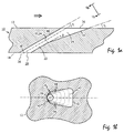
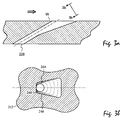
- FIGS. 2 (a), (b) show a known diffuser geometry with lateral expansion
- Figures 3 (a), (b) a known diffuser geometry with additional downstream Expansion of the film cooling hole.
- the first inner surface of the diffuser section is preferably elliptical, particularly preferably rounded in a circle.
- the specification of the curve shape refers to a section of the hole with a plane parallel to the outer surface.
- the Inner surface is the cutting edge of the inner surface with the outer surface itself be circular or elliptical.
- the radius of curvature can be along the axis of the Film cooling hole vary and then goes steadily from the curvature at the inlet of the Diffuser section over to the curvature on the outer surface.
- the first inner surface is designed so that it is in a smooth curve in the Side surfaces merges.
- the second inner surface is advantageously essentially flat and also advantageously merges into the side surfaces in a smooth curve.
- the first and second inner surfaces advantageously diverge to the outlet of the Diffuser section towards each other at an angle less than 30 °, preferred at an angle between 5 ° and 20 °. It is also advantageous if at least one of the side surfaces away from the axis of the film cooling hole at an angle greater than 5 °, preferably greater than 10 °, diverges. Diverge particularly advantageously both side surfaces at such an angle away from the axis.
- the axis each film cooling hole preferably makes an angle with the outer surface between 5 ° and 50 °, preferably between 15 ° and 40 °, particularly preferred between 25 ° and 35 °.
- each film cooling hole has one Feed section, the feed section having an inlet on the inner Surface and the outlet of the feed section, the inlet of the Diffuser section forms.
- the feed section has between its inlet and its outlet has a constant cross section, particularly preferably one constant elliptical cross section.
- the cross section of the feed section does not remain constant, but to Diffuser section through a step or a surface of another slope enlarged.
- the cooled wall forms the outer wall a hollow profile body, in particular a gas turbine blade.
- Figure 1 (a) shows a cross section through a wall 10 of a hollow profile body Gas turbine blade with a film cooling hole 20 according to the invention.
- the Film cooling hole 20 extends from the inner surface 14 to the outer Surface 12 of the wall 10. Flows in the direction of the arrow on the outer surface 12 Hot gas along.
- the inner surface 14 is a boundary surface Coolant chamber that contains pressurized chilled air.
- the film cooling hole has a cylindrical feed section 22, whose cross-section at the inlet 30 determines the amount of cooling air flowing through.
- the cooling air flows from the outlet 32 of the feed section 22 into the diffuser section 24.
- the cut edge of the first inner surface 40 is parallel to the axis 26 of the film cooling hole 20.
- the axis 26 emerges from the outer surface 12 at an angle of 30 °.
- the cut edges of the inner surfaces 40, 42 with the outer surface are designated by the reference symbols 50 and 52.
- the diffuser section further has side surfaces 44 and 46 which intersect the inner surfaces 40, 42. Both side surfaces 44, 46 diverge towards the outlet 36 of the diffuser section away from the axis 26 of the film cooling hole.
- the cooling air flow is quickly towards the Direction of flow of the hot gas is deflected so that the blown out cooling air as a protective film on the profile surface.
- the blowout rates are included small, so there is a risk that the cooling air through the flow boundary layer is small.
- the inner surface 40 is rounded in a circle toward the axis 26 of the film cooling hole 20. At the cutting edge 50, the intersection of the inner surface 40 with the outer surface 12, the radius of curvature R 2 .
- the feed section 22 is cylindrical with a constant cross section.
- the outlet 32 of the feed section coincides with the inlet 32 of the diffuser section 24 in this embodiment.
- the radius of curvature of the first inner surface 40 at the inlet 34 of the diffuser section is thus determined by the cylindrical feed section. Its value at this point is therefore d / 2 , where d denotes the diameter of the cylinder section.
- the radius of curvature of the inner surface 40 increases continuously and continuously from d / 2 to R 2 .
- the second inner surface 42 is essentially flat and merges with the side lines 44, 46 in a smooth curve with a radius of curvature R at the intersection lines.
- Figures 2 (b), 3 (b) are the first inner surfaces 140, 240 just designed. They go in the cases shown in Figures 2 (b) and 3 (b) in a smooth curve in the side surfaces 144, 146 and 244, 246 over, it remains however always a flat section of considerable size. Near edges 150 or 250, the wall thickness is particularly small (reference symbol W in FIGS. 2 (a), 3 (a)) and thus susceptible to foreign object impact. Rounding off the first Inner surface 40 in the invention the stiffness of this area becomes significant increased, since the forces generated in the impact laterally into areas with larger Wall thickness can be deflected. In addition, by rounding out the critical area of the outer surface 12, under which areas are very small Wall thickness are significantly reduced compared to the known designs.
- the edge 52 is still non-circular designed. This does not adversely affect the stability of the hole, however the wall at edge 52 has almost its maximum thickness.
- the stability of the Film cooling hole 20 of FIG. 1 thus reaches the stability of cylindrical cooling holes approach.
- the cooling properties are due to the little change Ratio of diffuser opening to supply opening a cylinder hole wide think.
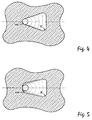
- the first inner surface 440 is elliptical rounded, i.e. the cross sections of the film cooling hole with planes parallel to the outer The surface shows an elliptical arc as the cut edge.
- FIG. 6 shows an embodiment in which the first inner surface 540 is rounded by using two basket arches with different radii R 1 , R 2 .
- Such an embodiment is particularly expedient if the axis of the film cooling holes has an additional lateral angle to the hot gas flow. In some situations it is advantageous to widen the film cooling holes laterally only to one side. Even in such a case, the use of two basket arches with a different radius is expedient for the expanded and the non-expanded side (FIG. 7).
Landscapes
- Engineering & Computer Science (AREA)
- Mechanical Engineering (AREA)
- General Engineering & Computer Science (AREA)
- Turbine Rotor Nozzle Sealing (AREA)
Priority Applications (3)
| Application Number | Priority Date | Filing Date | Title |
|---|---|---|---|
| DE59808269T DE59808269D1 (de) | 1998-03-23 | 1998-03-23 | Filmkühlungsbohrung |
| EP98810253A EP0945593B1 (fr) | 1998-03-23 | 1998-03-23 | Trou de refroidissement pelliculaire |
| US09/271,267 US6183199B1 (en) | 1998-03-23 | 1999-03-17 | Cooling-air bore |
Applications Claiming Priority (1)
| Application Number | Priority Date | Filing Date | Title |
|---|---|---|---|
| EP98810253A EP0945593B1 (fr) | 1998-03-23 | 1998-03-23 | Trou de refroidissement pelliculaire |
Publications (2)
| Publication Number | Publication Date |
|---|---|
| EP0945593A1 true EP0945593A1 (fr) | 1999-09-29 |
| EP0945593B1 EP0945593B1 (fr) | 2003-05-07 |
Family
ID=8236008
Family Applications (1)
| Application Number | Title | Priority Date | Filing Date |
|---|---|---|---|
| EP98810253A Expired - Lifetime EP0945593B1 (fr) | 1998-03-23 | 1998-03-23 | Trou de refroidissement pelliculaire |
Country Status (3)
| Country | Link |
|---|---|
| US (1) | US6183199B1 (fr) |
| EP (1) | EP0945593B1 (fr) |
| DE (1) | DE59808269D1 (fr) |
Cited By (8)
| Publication number | Priority date | Publication date | Assignee | Title |
|---|---|---|---|---|
| EP1645721A3 (fr) * | 2004-10-04 | 2009-10-07 | ALSTOM Technology Ltd | Aube de turbine à gaz avec refroidissement du bord d'attaque |
| EP1517003A3 (fr) * | 2003-09-17 | 2012-07-11 | General Electric Company | Aube de turbomachine refroidie |
| EP1898051A3 (fr) * | 2006-08-25 | 2013-05-15 | Alstom Technology Ltd | Aube de turbine à gaz avec refroidissement du bord d'attaque |
| EP3015648A1 (fr) * | 2014-10-30 | 2016-05-04 | Rolls-Royce plc | Composant refroidi |
| EP3061911A1 (fr) * | 2015-02-24 | 2016-08-31 | General Electric Company | Composant de moteur |
| WO2017162743A1 (fr) * | 2016-03-23 | 2017-09-28 | Siemens Aktiengesellschaft | Trou pour film d'air de refroidissement dans des pièces de turbine à gaz |
| EP3450682A1 (fr) | 2017-08-30 | 2019-03-06 | Siemens Aktiengesellschaft | Paroi d'un composant pour gaz chaud et composant associé |
| DE102018108729A1 (de) | 2018-04-12 | 2019-10-17 | Karlsruher Institut für Technologie | Strömungsleitfläche, strömungsführende Komponente einer Verbrennungskraftmaschine sowie eine Turbinenschaufel |
Families Citing this family (87)
| Publication number | Priority date | Publication date | Assignee | Title |
|---|---|---|---|---|
| US6383602B1 (en) * | 1996-12-23 | 2002-05-07 | General Electric Company | Method for improving the cooling effectiveness of a gaseous coolant stream which flows through a substrate, and related articles of manufacture |
| US6428172B1 (en) * | 1999-11-24 | 2002-08-06 | Donnelly Corporation | Rearview mirror assembly with utility functions |
| US6368060B1 (en) * | 2000-05-23 | 2002-04-09 | General Electric Company | Shaped cooling hole for an airfoil |
| US6672829B1 (en) | 2002-07-16 | 2004-01-06 | General Electric Company | Turbine blade having angled squealer tip |
| US6918742B2 (en) * | 2002-09-05 | 2005-07-19 | Siemens Westinghouse Power Corporation | Combustion turbine with airfoil having multi-section diffusion cooling holes and methods of making same |
| US6994514B2 (en) * | 2002-11-20 | 2006-02-07 | Mitsubishi Heavy Industries, Ltd. | Turbine blade and gas turbine |
| US7041933B2 (en) * | 2003-04-14 | 2006-05-09 | Meyer Tool, Inc. | Complex hole shaping |
| US20060073015A1 (en) * | 2004-10-01 | 2006-04-06 | Alstom Technology Ltd. | Gas turbine airfoil film cooling hole |
| US7246992B2 (en) * | 2005-01-28 | 2007-07-24 | General Electric Company | High efficiency fan cooling holes for turbine airfoil |
| DE102005015153B4 (de) * | 2005-03-31 | 2017-03-09 | General Electric Technology Gmbh | Verfahren zum Reparieren oder Erneuern von Kühllöchern einer beschichteten Komponente und beschichtete Komponente mit Kühllöchern einer Gasturbine |
| EP1712739A1 (fr) * | 2005-04-12 | 2006-10-18 | Siemens Aktiengesellschaft | Elément avec trou de refroidissement par film |
| FR2895691A1 (fr) * | 2006-01-12 | 2007-07-06 | Snecma Sa | Element de paroi dans lequel est menage un canal de refroidissement |
| JP4931507B2 (ja) * | 2005-07-26 | 2012-05-16 | スネクマ | 壁内に形成された冷却流路 |
| FR2896710B1 (fr) * | 2006-01-27 | 2009-10-30 | Snecma Sa | Procede de fabrication de piece de turbomachine comportant des orifices d'evacuation d'air de refroidissement |
| US7563073B1 (en) | 2006-10-10 | 2009-07-21 | Florida Turbine Technologies, Inc. | Turbine blade with film cooling slot |
| US7887294B1 (en) | 2006-10-13 | 2011-02-15 | Florida Turbine Technologies, Inc. | Turbine airfoil with continuous curved diffusion film holes |
| RU2418174C2 (ru) * | 2006-11-16 | 2011-05-10 | Снекма | Канал охлаждения, выполненный в стенке |
| US7704047B2 (en) * | 2006-11-21 | 2010-04-27 | Siemens Energy, Inc. | Cooling of turbine blade suction tip rail |
| US20080271457A1 (en) * | 2007-05-01 | 2008-11-06 | General Electric Company | Cooling Holes For Gas Turbine Combustor Having A Non-Uniform Diameter Therethrough |
| US8066484B1 (en) | 2007-11-19 | 2011-11-29 | Florida Turbine Technologies, Inc. | Film cooling hole for a turbine airfoil |
| FR2926481B1 (fr) * | 2008-01-23 | 2011-09-23 | Snecma | Canal de refroidissement menage dans une paroi |
| US8105030B2 (en) * | 2008-08-14 | 2012-01-31 | United Technologies Corporation | Cooled airfoils and gas turbine engine systems involving such airfoils |
| US8092177B2 (en) * | 2008-09-16 | 2012-01-10 | Siemens Energy, Inc. | Turbine airfoil cooling system with diffusion film cooling hole having flow restriction rib |
| US8079810B2 (en) * | 2008-09-16 | 2011-12-20 | Siemens Energy, Inc. | Turbine airfoil cooling system with divergent film cooling hole |
| US8092176B2 (en) | 2008-09-16 | 2012-01-10 | Siemens Energy, Inc. | Turbine airfoil cooling system with curved diffusion film cooling hole |
| US8328517B2 (en) * | 2008-09-16 | 2012-12-11 | Siemens Energy, Inc. | Turbine airfoil cooling system with diffusion film cooling hole |
| US8057179B1 (en) | 2008-10-16 | 2011-11-15 | Florida Turbine Technologies, Inc. | Film cooling hole for turbine airfoil |
| US8057180B1 (en) | 2008-11-07 | 2011-11-15 | Florida Turbine Technologies, Inc. | Shaped film cooling hole for turbine airfoil |
| US8057181B1 (en) | 2008-11-07 | 2011-11-15 | Florida Turbine Technologies, Inc. | Multiple expansion film cooling hole for turbine airfoil |
| US8245519B1 (en) | 2008-11-25 | 2012-08-21 | Florida Turbine Technologies, Inc. | Laser shaped film cooling hole |
| US8092178B2 (en) * | 2008-11-28 | 2012-01-10 | Pratt & Whitney Canada Corp. | Turbine blade for a gas turbine engine |
| US8167536B2 (en) * | 2009-03-04 | 2012-05-01 | Siemens Energy, Inc. | Turbine blade leading edge tip cooling system |
| EP2230383A1 (fr) * | 2009-03-18 | 2010-09-22 | Alstom Technology Ltd | Aube de turbine avec refroidissement de l'extrémité |
| GB0912796D0 (en) * | 2009-07-23 | 2009-08-26 | Cummins Turbo Tech Ltd | Compressor,turbine and turbocharger |
| US8742279B2 (en) * | 2010-02-01 | 2014-06-03 | United Technologies Corporation | Method of creating an airfoil trench and a plurality of cooling holes within the trench |
| US8672613B2 (en) | 2010-08-31 | 2014-03-18 | General Electric Company | Components with conformal curved film holes and methods of manufacture |
| RU2473813C1 (ru) * | 2011-07-29 | 2013-01-27 | Открытое акционерное общество "Научно-производственное объединение "Сатурн" (ОАО "НПО "Сатурн") | Сопловой аппарат турбомашины с конвективно-пленочным охлаждением |
| JP5536001B2 (ja) * | 2011-09-20 | 2014-07-02 | 株式会社日立製作所 | ガスタービン翼フィルム冷却孔の設定方法及びガスタービン翼 |
| US9482100B2 (en) * | 2012-02-15 | 2016-11-01 | United Technologies Corporation | Multi-lobed cooling hole |
| US8733111B2 (en) | 2012-02-15 | 2014-05-27 | United Technologies Corporation | Cooling hole with asymmetric diffuser |
| US10422230B2 (en) | 2012-02-15 | 2019-09-24 | United Technologies Corporation | Cooling hole with curved metering section |
| US9279330B2 (en) | 2012-02-15 | 2016-03-08 | United Technologies Corporation | Gas turbine engine component with converging/diverging cooling passage |
| US9284844B2 (en) | 2012-02-15 | 2016-03-15 | United Technologies Corporation | Gas turbine engine component with cusped cooling hole |
| US8850828B2 (en) | 2012-02-15 | 2014-10-07 | United Technologies Corporation | Cooling hole with curved metering section |
| US9024226B2 (en) | 2012-02-15 | 2015-05-05 | United Technologies Corporation | EDM method for multi-lobed cooling hole |
| US9598979B2 (en) | 2012-02-15 | 2017-03-21 | United Technologies Corporation | Manufacturing methods for multi-lobed cooling holes |
| US8763402B2 (en) | 2012-02-15 | 2014-07-01 | United Technologies Corporation | Multi-lobed cooling hole and method of manufacture |
| US9273560B2 (en) | 2012-02-15 | 2016-03-01 | United Technologies Corporation | Gas turbine engine component with multi-lobed cooling hole |
| US8689568B2 (en) | 2012-02-15 | 2014-04-08 | United Technologies Corporation | Cooling hole with thermo-mechanical fatigue resistance |
| US9416971B2 (en) | 2012-02-15 | 2016-08-16 | United Technologies Corporation | Multiple diffusing cooling hole |
| US9422815B2 (en) | 2012-02-15 | 2016-08-23 | United Technologies Corporation | Gas turbine engine component with compound cusp cooling configuration |
| JP2013167205A (ja) * | 2012-02-15 | 2013-08-29 | Hitachi Ltd | ガスタービン翼、その放電加工用工具及び加工方法 |
| US9416665B2 (en) | 2012-02-15 | 2016-08-16 | United Technologies Corporation | Cooling hole with enhanced flow attachment |
| US8683813B2 (en) | 2012-02-15 | 2014-04-01 | United Technologies Corporation | Multi-lobed cooling hole and method of manufacture |
| US8683814B2 (en) | 2012-02-15 | 2014-04-01 | United Technologies Corporation | Gas turbine engine component with impingement and lobed cooling hole |
| US9410435B2 (en) | 2012-02-15 | 2016-08-09 | United Technologies Corporation | Gas turbine engine component with diffusive cooling hole |
| US8522558B1 (en) | 2012-02-15 | 2013-09-03 | United Technologies Corporation | Multi-lobed cooling hole array |
| US8707713B2 (en) | 2012-02-15 | 2014-04-29 | United Technologies Corporation | Cooling hole with crenellation features |
| US8584470B2 (en) | 2012-02-15 | 2013-11-19 | United Technologies Corporation | Tri-lobed cooling hole and method of manufacture |
| US8572983B2 (en) | 2012-02-15 | 2013-11-05 | United Technologies Corporation | Gas turbine engine component with impingement and diffusive cooling |
| US9650900B2 (en) | 2012-05-07 | 2017-05-16 | Honeywell International Inc. | Gas turbine engine components with film cooling holes having cylindrical to multi-lobe configurations |
| US20130315710A1 (en) * | 2012-05-22 | 2013-11-28 | Honeywell International Inc. | Gas turbine engine components with cooling hole trenches |
| US10386069B2 (en) | 2012-06-13 | 2019-08-20 | General Electric Company | Gas turbine engine wall |
| US10113433B2 (en) | 2012-10-04 | 2018-10-30 | Honeywell International Inc. | Gas turbine engine components with lateral and forward sweep film cooling holes |
| US9309771B2 (en) * | 2012-10-25 | 2016-04-12 | United Technologies Corporation | Film cooling channel array with multiple metering portions |
| WO2014137470A1 (fr) | 2013-03-05 | 2014-09-12 | Vandervaart Peter L | Agencement de composant pour moteur à turbine à gaz |
| WO2014163698A1 (fr) | 2013-03-07 | 2014-10-09 | Vandervaart Peter L | Pièce refroidie de turbine à gaz |
| WO2015065587A1 (fr) | 2013-11-04 | 2015-05-07 | United Technologies Corporation | Passage de refroidissement revêtu |
| US10041356B2 (en) * | 2014-08-15 | 2018-08-07 | United Technologies Corporation | Showerhead hole scheme apparatus and system |
| CN104234756B (zh) * | 2014-09-15 | 2016-08-24 | 西北工业大学 | 一种跨音速型气膜冷却孔 |
| US20160090843A1 (en) * | 2014-09-30 | 2016-03-31 | General Electric Company | Turbine components with stepped apertures |
| EP3034803A1 (fr) | 2014-12-16 | 2016-06-22 | Rolls-Royce Corporation | Système de suspension d'un composant de moteur à turbine |
| US10400607B2 (en) | 2014-12-30 | 2019-09-03 | United Technologies Corporation | Large-footprint turbine cooling hole |
| US20160298462A1 (en) * | 2015-04-09 | 2016-10-13 | United Technologies Corporation | Cooling passages for a gas turbine engine component |
| US10208602B2 (en) * | 2015-04-27 | 2019-02-19 | United Technologies Corporation | Asymmetric diffuser opening for film cooling holes |
| CA2933884A1 (fr) * | 2015-06-30 | 2016-12-30 | Rolls-Royce Corporation | Tuile de combustor |
| US20170298743A1 (en) * | 2016-04-14 | 2017-10-19 | General Electric Company | Component for a turbine engine with a film-hole |
| US10458251B2 (en) * | 2016-04-15 | 2019-10-29 | General Electric Company | Airfoil cooling using non-line of sight holes |
| US11021965B2 (en) | 2016-05-19 | 2021-06-01 | Honeywell International Inc. | Engine components with cooling holes having tailored metering and diffuser portions |
| US10605092B2 (en) | 2016-07-11 | 2020-03-31 | United Technologies Corporation | Cooling hole with shaped meter |
| US10443401B2 (en) * | 2016-09-02 | 2019-10-15 | United Technologies Corporation | Cooled turbine vane with alternately orientated film cooling hole rows |
| US10760431B2 (en) * | 2017-09-07 | 2020-09-01 | General Electric Company | Component for a turbine engine with a cooling hole |
| US10539026B2 (en) | 2017-09-21 | 2020-01-21 | United Technologies Corporation | Gas turbine engine component with cooling holes having variable roughness |
| US11359494B2 (en) * | 2019-08-06 | 2022-06-14 | General Electric Company | Engine component with cooling hole |
| CN110761846A (zh) * | 2019-11-26 | 2020-02-07 | 上海电气燃气轮机有限公司 | 气膜孔 |
| CN116085117A (zh) * | 2023-04-10 | 2023-05-09 | 清华大学 | 导向结构 |
| US20260063295A1 (en) * | 2024-08-07 | 2026-03-05 | Rtx Corporation | Elliptical-rectangular film cooling hole |
Citations (6)
| Publication number | Priority date | Publication date | Assignee | Title |
|---|---|---|---|---|
| US3457619A (en) * | 1967-11-28 | 1969-07-29 | Gen Electric | Production of perforated metallic bodies |
| US4197443A (en) | 1977-09-19 | 1980-04-08 | General Electric Company | Method and apparatus for forming diffused cooling holes in an airfoil |
| EP0228338B1 (fr) | 1985-12-23 | 1992-01-29 | United Technologies Corporation | Passages de refroidissement avec des coins arrondis |
| US5261789A (en) * | 1992-08-25 | 1993-11-16 | General Electric Company | Tip cooled blade |
| US5271715A (en) * | 1992-12-21 | 1993-12-21 | United Technologies Corporation | Cooled turbine blade |
| US5382133A (en) * | 1993-10-15 | 1995-01-17 | United Technologies Corporation | High coverage shaped diffuser film hole for thin walls |
Family Cites Families (5)
| Publication number | Priority date | Publication date | Assignee | Title |
|---|---|---|---|---|
| US4606701A (en) * | 1981-09-02 | 1986-08-19 | Westinghouse Electric Corp. | Tip structure for a cooled turbine rotor blade |
| US4705455A (en) * | 1985-12-23 | 1987-11-10 | United Technologies Corporation | Convergent-divergent film coolant passage |
| US5183385A (en) * | 1990-11-19 | 1993-02-02 | General Electric Company | Turbine blade squealer tip having air cooling holes contiguous with tip interior wall surface |
| US5192192A (en) * | 1990-11-28 | 1993-03-09 | The United States Of America As Represented By The Secretary Of The Air Force | Turbine engine foil cap |
| US5779437A (en) * | 1996-10-31 | 1998-07-14 | Pratt & Whitney Canada Inc. | Cooling passages for airfoil leading edge |
-
1998
- 1998-03-23 EP EP98810253A patent/EP0945593B1/fr not_active Expired - Lifetime
- 1998-03-23 DE DE59808269T patent/DE59808269D1/de not_active Expired - Lifetime
-
1999
- 1999-03-17 US US09/271,267 patent/US6183199B1/en not_active Expired - Lifetime
Patent Citations (6)
| Publication number | Priority date | Publication date | Assignee | Title |
|---|---|---|---|---|
| US3457619A (en) * | 1967-11-28 | 1969-07-29 | Gen Electric | Production of perforated metallic bodies |
| US4197443A (en) | 1977-09-19 | 1980-04-08 | General Electric Company | Method and apparatus for forming diffused cooling holes in an airfoil |
| EP0228338B1 (fr) | 1985-12-23 | 1992-01-29 | United Technologies Corporation | Passages de refroidissement avec des coins arrondis |
| US5261789A (en) * | 1992-08-25 | 1993-11-16 | General Electric Company | Tip cooled blade |
| US5271715A (en) * | 1992-12-21 | 1993-12-21 | United Technologies Corporation | Cooled turbine blade |
| US5382133A (en) * | 1993-10-15 | 1995-01-17 | United Technologies Corporation | High coverage shaped diffuser film hole for thin walls |
Cited By (11)
| Publication number | Priority date | Publication date | Assignee | Title |
|---|---|---|---|---|
| EP1517003A3 (fr) * | 2003-09-17 | 2012-07-11 | General Electric Company | Aube de turbomachine refroidie |
| EP1645721A3 (fr) * | 2004-10-04 | 2009-10-07 | ALSTOM Technology Ltd | Aube de turbine à gaz avec refroidissement du bord d'attaque |
| EP1898051A3 (fr) * | 2006-08-25 | 2013-05-15 | Alstom Technology Ltd | Aube de turbine à gaz avec refroidissement du bord d'attaque |
| EP3015648A1 (fr) * | 2014-10-30 | 2016-05-04 | Rolls-Royce plc | Composant refroidi |
| US9957811B2 (en) | 2014-10-30 | 2018-05-01 | Rolls-Royce Plc | Cooled component |
| EP3061911A1 (fr) * | 2015-02-24 | 2016-08-31 | General Electric Company | Composant de moteur |
| WO2017162743A1 (fr) * | 2016-03-23 | 2017-09-28 | Siemens Aktiengesellschaft | Trou pour film d'air de refroidissement dans des pièces de turbine à gaz |
| EP3450682A1 (fr) | 2017-08-30 | 2019-03-06 | Siemens Aktiengesellschaft | Paroi d'un composant pour gaz chaud et composant associé |
| WO2019042970A1 (fr) | 2017-08-30 | 2019-03-07 | Siemens Aktiengesellschaft | Paroi d'un composant implanté dans un trajet de gaz chaud et composant implanté dans un trajet de gaz chaud comprenant une paroi |
| US11525361B2 (en) | 2017-08-30 | 2022-12-13 | Siemens Energy Global GmbH & Co. KG | Wall of a hot gas component and hot gas component comprising a wall |
| DE102018108729A1 (de) | 2018-04-12 | 2019-10-17 | Karlsruher Institut für Technologie | Strömungsleitfläche, strömungsführende Komponente einer Verbrennungskraftmaschine sowie eine Turbinenschaufel |
Also Published As
| Publication number | Publication date |
|---|---|
| US6183199B1 (en) | 2001-02-06 |
| EP0945593B1 (fr) | 2003-05-07 |
| DE59808269D1 (de) | 2003-06-12 |
Similar Documents
| Publication | Publication Date | Title |
|---|---|---|
| EP0945593B1 (fr) | Trou de refroidissement pelliculaire | |
| EP0985802B1 (fr) | Méthode de formation d'un orifice pour le refroidissement par pellicule | |
| EP0798448B1 (fr) | Système et dispositif pour réfroidir une paroi chauffée d'un côté par un gaz chaud | |
| EP0950463B1 (fr) | Perforation non-circulaire de refroidissement et procédé pour sa fabrication | |
| DE10059997B4 (de) | Kühlbare Schaufel für eine Gasturbinenkomponente | |
| DE102006026853A1 (de) | Spanabhebendes Werkzeug | |
| DE10215833B4 (de) | Schneidkörper mit einem Schlegel | |
| EP0523313A1 (fr) | Elément pour éporateur | |
| EP0707129B1 (fr) | Outil de forage avec support et éléments de coupe | |
| DE102004023270A1 (de) | Axialschraubengebläse | |
| DE69524621T2 (de) | Gesteinsbohrer sowie schneideinsätze | |
| DE1477708A1 (de) | Spanabhebend arbeitender Drehbohrer | |
| DE69415719T2 (de) | Düsenanordnung für Fräsbohrmeissel | |
| DE102009041812A1 (de) | Fräser mit einer schaftartigen Grundform | |
| DE102019103248A1 (de) | Laserbearbeitungskopf mit der Funktion des Gleichrichtens von Hilfsgas | |
| DE69408326T2 (de) | Plasmabrenner | |
| EP3473808B1 (fr) | Pale d'aube pour une aube mobile de turbine à refroidissement intérieur ainsi que procédé de fabrication d'une telle pale | |
| WO2017020051A1 (fr) | Tête de coupe remplaçable, tige d'outil et outil à tige | |
| EP3807036B1 (fr) | Foret long et outil de fond comportant une ou plusieurs cavités dans la face de coupe | |
| DE60213542T2 (de) | Bürstendichtungselement | |
| DE102017118583B4 (de) | Anordnung von Stützstreben in einem abstromseitigen Ringraum einer Gasturbine | |
| EP1288435A2 (fr) | Aube de turbine avec au moins un orifice de refroidissement | |
| WO2009007097A1 (fr) | Procédé pour refroidir et lubrifier un outil de machine, dispositif pour mettre en œuvre ce procédé et outil de machine | |
| DE2649323A1 (de) | Bohrerspitzenkonstruktion | |
| DE4033877B4 (de) | Bohrwerkzeug |
Legal Events
| Date | Code | Title | Description |
|---|---|---|---|
| PUAI | Public reference made under article 153(3) epc to a published international application that has entered the european phase |
Free format text: ORIGINAL CODE: 0009012 |
|
| AK | Designated contracting states |
Kind code of ref document: A1 Designated state(s): DE GB |
|
| AX | Request for extension of the european patent |
Free format text: AL;LT;LV;MK;RO;SI |
|
| 17P | Request for examination filed |
Effective date: 20000216 |
|
| AKX | Designation fees paid |
Free format text: DE GB |
|
| RAP1 | Party data changed (applicant data changed or rights of an application transferred) |
Owner name: ALSTOM |
|
| 17Q | First examination report despatched |
Effective date: 20020321 |
|
| GRAH | Despatch of communication of intention to grant a patent |
Free format text: ORIGINAL CODE: EPIDOS IGRA |
|
| RAP1 | Party data changed (applicant data changed or rights of an application transferred) |
Owner name: ALSTOM (SWITZERLAND) LTD |
|
| GRAH | Despatch of communication of intention to grant a patent |
Free format text: ORIGINAL CODE: EPIDOS IGRA |
|
| GRAA | (expected) grant |
Free format text: ORIGINAL CODE: 0009210 |
|
| AK | Designated contracting states |
Designated state(s): DE GB |
|
| REG | Reference to a national code |
Ref country code: GB Ref legal event code: FG4D Free format text: NOT ENGLISH |
|
| REF | Corresponds to: |
Ref document number: 59808269 Country of ref document: DE Date of ref document: 20030612 Kind code of ref document: P |
|
| GBT | Gb: translation of ep patent filed (gb section 77(6)(a)/1977) | ||
| PLBE | No opposition filed within time limit |
Free format text: ORIGINAL CODE: 0009261 |
|
| STAA | Information on the status of an ep patent application or granted ep patent |
Free format text: STATUS: NO OPPOSITION FILED WITHIN TIME LIMIT |
|
| 26N | No opposition filed |
Effective date: 20040210 |
|
| REG | Reference to a national code |
Ref country code: DE Ref legal event code: R082 Ref document number: 59808269 Country of ref document: DE Representative=s name: UWE ROESLER, DE |
|
| REG | Reference to a national code |
Ref country code: GB Ref legal event code: 732E Free format text: REGISTERED BETWEEN 20120802 AND 20120808 |
|
| REG | Reference to a national code |
Ref country code: DE Ref legal event code: R082 Ref document number: 59808269 Country of ref document: DE Representative=s name: ROESLER, UWE, DIPL.-PHYS.UNIV., DE Effective date: 20120713 Ref country code: DE Ref legal event code: R081 Ref document number: 59808269 Country of ref document: DE Owner name: ANSALDO ENERGIA IP UK LIMITED, GB Free format text: FORMER OWNER: ALSTOM (SWITZERLAND) LTD., BADEN, CH Effective date: 20120713 Ref country code: DE Ref legal event code: R081 Ref document number: 59808269 Country of ref document: DE Owner name: GENERAL ELECTRIC TECHNOLOGY GMBH, CH Free format text: FORMER OWNER: ALSTOM (SWITZERLAND) LTD., BADEN, CH Effective date: 20120713 Ref country code: DE Ref legal event code: R081 Ref document number: 59808269 Country of ref document: DE Owner name: ALSTOM TECHNOLOGY LTD., CH Free format text: FORMER OWNER: ALSTOM (SWITZERLAND) LTD., BADEN, CH Effective date: 20120713 |
|
| REG | Reference to a national code |
Ref country code: DE Ref legal event code: R082 Ref document number: 59808269 Country of ref document: DE Representative=s name: ROESLER, UWE, DIPL.-PHYS.UNIV., DE Ref country code: DE Ref legal event code: R081 Ref document number: 59808269 Country of ref document: DE Owner name: ANSALDO ENERGIA IP UK LIMITED, GB Free format text: FORMER OWNER: ALSTOM TECHNOLOGY LTD., BADEN, CH Ref country code: DE Ref legal event code: R081 Ref document number: 59808269 Country of ref document: DE Owner name: GENERAL ELECTRIC TECHNOLOGY GMBH, CH Free format text: FORMER OWNER: ALSTOM TECHNOLOGY LTD., BADEN, CH |
|
| PGFP | Annual fee paid to national office [announced via postgrant information from national office to epo] |
Ref country code: DE Payment date: 20170322 Year of fee payment: 20 |
|
| PGFP | Annual fee paid to national office [announced via postgrant information from national office to epo] |
Ref country code: GB Payment date: 20170322 Year of fee payment: 20 |
|
| REG | Reference to a national code |
Ref country code: DE Ref legal event code: R082 Ref document number: 59808269 Country of ref document: DE Representative=s name: ROESLER, UWE, DIPL.-PHYS.UNIV., DE Ref country code: DE Ref legal event code: R081 Ref document number: 59808269 Country of ref document: DE Owner name: ANSALDO ENERGIA IP UK LIMITED, GB Free format text: FORMER OWNER: GENERAL ELECTRIC TECHNOLOGY GMBH, BADEN, CH |
|
| REG | Reference to a national code |
Ref country code: GB Ref legal event code: 732E Free format text: REGISTERED BETWEEN 20170824 AND 20170830 |
|
| REG | Reference to a national code |
Ref country code: DE Ref legal event code: R071 Ref document number: 59808269 Country of ref document: DE |
|
| REG | Reference to a national code |
Ref country code: GB Ref legal event code: PE20 Expiry date: 20180322 |
|
| PG25 | Lapsed in a contracting state [announced via postgrant information from national office to epo] |
Ref country code: GB Free format text: LAPSE BECAUSE OF EXPIRATION OF PROTECTION Effective date: 20180322 |