EP0945609A2 - Méthode et dispositif pour commuter une charge inductive - Google Patents
Méthode et dispositif pour commuter une charge inductive Download PDFInfo
- Publication number
- EP0945609A2 EP0945609A2 EP98117685A EP98117685A EP0945609A2 EP 0945609 A2 EP0945609 A2 EP 0945609A2 EP 98117685 A EP98117685 A EP 98117685A EP 98117685 A EP98117685 A EP 98117685A EP 0945609 A2 EP0945609 A2 EP 0945609A2
- Authority
- EP
- European Patent Office
- Prior art keywords
- consumer
- connection
- switching means
- switching
- capacitor
- Prior art date
- Legal status (The legal status is an assumption and is not a legal conclusion. Google has not performed a legal analysis and makes no representation as to the accuracy of the status listed.)
- Granted
Links
- 238000000034 method Methods 0.000 title claims abstract description 16
- 230000001939 inductive effect Effects 0.000 title claims abstract description 8
- 239000003990 capacitor Substances 0.000 claims description 35
- 230000005611 electricity Effects 0.000 claims description 8
- 238000002347 injection Methods 0.000 description 6
- 239000007924 injection Substances 0.000 description 6
- 230000006870 function Effects 0.000 description 5
- 230000001276 controlling effect Effects 0.000 description 4
- 238000004146 energy storage Methods 0.000 description 4
- 238000004804 winding Methods 0.000 description 4
- 238000002485 combustion reaction Methods 0.000 description 3
- 239000000446 fuel Substances 0.000 description 3
- 238000005265 energy consumption Methods 0.000 description 2
- 230000003213 activating effect Effects 0.000 description 1
- 238000011161 development Methods 0.000 description 1
- 230000018109 developmental process Effects 0.000 description 1
- 238000010586 diagram Methods 0.000 description 1
- 230000005669 field effect Effects 0.000 description 1
- 230000006698 induction Effects 0.000 description 1
- 230000001105 regulatory effect Effects 0.000 description 1
Images




Classifications
-
- F—MECHANICAL ENGINEERING; LIGHTING; HEATING; WEAPONS; BLASTING
- F02—COMBUSTION ENGINES; HOT-GAS OR COMBUSTION-PRODUCT ENGINE PLANTS
- F02D—CONTROLLING COMBUSTION ENGINES
- F02D41/00—Electrical control of supply of combustible mixture or its constituents
- F02D41/20—Output circuits, e.g. for controlling currents in command coils
-
- H—ELECTRICITY
- H01—ELECTRIC ELEMENTS
- H01F—MAGNETS; INDUCTANCES; TRANSFORMERS; SELECTION OF MATERIALS FOR THEIR MAGNETIC PROPERTIES
- H01F7/00—Magnets
- H01F7/06—Electromagnets; Actuators including electromagnets
- H01F7/08—Electromagnets; Actuators including electromagnets with armatures
- H01F7/18—Circuit arrangements for obtaining desired operating characteristics, e.g. for slow operation, for sequential energisation of windings, for high-speed energisation of windings
- H01F7/1883—Circuit arrangements for obtaining desired operating characteristics, e.g. for slow operation, for sequential energisation of windings, for high-speed energisation of windings by steepening leading and trailing edges of magnetisation pulse, e.g. printer drivers
-
- F—MECHANICAL ENGINEERING; LIGHTING; HEATING; WEAPONS; BLASTING
- F02—COMBUSTION ENGINES; HOT-GAS OR COMBUSTION-PRODUCT ENGINE PLANTS
- F02D—CONTROLLING COMBUSTION ENGINES
- F02D41/00—Electrical control of supply of combustible mixture or its constituents
- F02D41/20—Output circuits, e.g. for controlling currents in command coils
- F02D2041/2003—Output circuits, e.g. for controlling currents in command coils using means for creating a boost voltage, i.e. generation or use of a voltage higher than the battery voltage, e.g. to speed up injector opening
-
- F—MECHANICAL ENGINEERING; LIGHTING; HEATING; WEAPONS; BLASTING
- F02—COMBUSTION ENGINES; HOT-GAS OR COMBUSTION-PRODUCT ENGINE PLANTS
- F02D—CONTROLLING COMBUSTION ENGINES
- F02D41/00—Electrical control of supply of combustible mixture or its constituents
- F02D41/20—Output circuits, e.g. for controlling currents in command coils
- F02D2041/2003—Output circuits, e.g. for controlling currents in command coils using means for creating a boost voltage, i.e. generation or use of a voltage higher than the battery voltage, e.g. to speed up injector opening
- F02D2041/2006—Output circuits, e.g. for controlling currents in command coils using means for creating a boost voltage, i.e. generation or use of a voltage higher than the battery voltage, e.g. to speed up injector opening by using a boost capacitor
-
- F—MECHANICAL ENGINEERING; LIGHTING; HEATING; WEAPONS; BLASTING
- F02—COMBUSTION ENGINES; HOT-GAS OR COMBUSTION-PRODUCT ENGINE PLANTS
- F02D—CONTROLLING COMBUSTION ENGINES
- F02D41/00—Electrical control of supply of combustible mixture or its constituents
- F02D41/20—Output circuits, e.g. for controlling currents in command coils
- F02D2041/2003—Output circuits, e.g. for controlling currents in command coils using means for creating a boost voltage, i.e. generation or use of a voltage higher than the battery voltage, e.g. to speed up injector opening
- F02D2041/201—Output circuits, e.g. for controlling currents in command coils using means for creating a boost voltage, i.e. generation or use of a voltage higher than the battery voltage, e.g. to speed up injector opening by using a boost inductance
-
- F—MECHANICAL ENGINEERING; LIGHTING; HEATING; WEAPONS; BLASTING
- F02—COMBUSTION ENGINES; HOT-GAS OR COMBUSTION-PRODUCT ENGINE PLANTS
- F02D—CONTROLLING COMBUSTION ENGINES
- F02D41/00—Electrical control of supply of combustible mixture or its constituents
- F02D41/20—Output circuits, e.g. for controlling currents in command coils
- F02D2041/2068—Output circuits, e.g. for controlling currents in command coils characterised by the circuit design or special circuit elements
- F02D2041/2079—Output circuits, e.g. for controlling currents in command coils characterised by the circuit design or special circuit elements the circuit having several coils acting on the same anchor
Definitions
- the invention relates to a method and a device for switching an inductive consumer according to General terms of the independent claims.
- the invention is based, with one Method and a device for controlling a inductive consumer as simple as possible Provide facility at which the power-up process accelerated and the total energy consumption is minimized.
- a controller is designated 100. This processes the Output signals from various sensors 110. Starting from It controls the fuel injection based on these sensor signals by controlling various solenoid valves.
- the Solenoid valves also known as inductive consumers are designated EV1, EV2, EV3 and EV4.
- EV1, EV2, EV3 and EV4 By doing
- the illustrated embodiment is a Internal combustion engine with four cylinders.
- the invention The procedure is also with internal combustion engines different number of cylinders, then a corresponding number EVN must be provided by consumers.
- the second connection of the consumer EV1 to EV4 is each with a switching means T1, T2, T3 and T4 Earth connection in contact.
- the switching means as transistors are exemplary embodiments educated.
- the control connections of the switching means are applied by the control 100 with control signals.
- the second connections of the consumers are in each case via at least one diode with the first connection of a other consumer in connection.
- the second stands Connection of the consumer EV1 via a diode D12 with the first connection of the consumer EV2 in connection.
- the second connection of the second stands accordingly Consumer EV2 via the diodes D23 and D24 with the first Connection of the third or fourth consumer in Contact.
- the second connection of the third consumer EV3 is connected via diodes D31 and D34 to the first connection of the first consumer EV1 and the fourth consumer EV4 in Contact.
- the second connection of the fourth consumer EV4 stands over diodes DV1 and DV2 with the first connection of the first and second consumers in contact.
- the diodes D12, D13, D24, D23, D31, D34, D41 and D42 are wired so that their anode with the second Connection of a consumer and the cathode with the first Another consumer is connected.
- the second connection of a consumer via two diodes with the first connection of two other consumers in contact can also be provided that the second connection of a consumer only over a diode with the first connection of another Is in contact with the consumer. It can also be provided that the second connection of each consumer via diodes with the first connections of all other consumers in Connection is established.
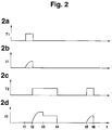
- FIG 2 there are various signals over time t applied.
- part figure 2a) is the control signal for the Transistor T1
- in the second sub-figure 2b) is the through the first consumer EV1 flowing current I1
- in partial figure 3c) is the control signal for the switch T2 and in Part 2d) the flowing through the second consumer Current I2 plotted.
- FIG. 1 The mode of operation of FIG. 1 is described below illustrated embodiment with reference to FIG. 2 clarifies. For simplification, it is provided that the Consumers only via one diode with another Communicate with consumers.
- consumer EV2 takes over Energy storage for the fourth consumer EV4.
- To the Time t6 then becomes the next consumer in particular EV4 switched on. It is particularly advantageous that a suitable cascading of the output stages one or several consumers are storing energy for others takes over.
- FIG. 1 In this embodiment shown in Figure 1 is used one or more consumers each as energy storage for another consumer.
- Figure 3 is an embodiment shown in which an additional inductance is provided, which serves as an energy store.
- the single ones Consumers EV1 to EV4 each have a switching device T1 to T4 connected to ground.
- the first connections of the Consumer EV1 to EV4 stand with the cathode of a diode D11 and a second terminal of a capacitor C11 in Connection.
- the anode of the diode D11 and the first connection of the capacitor C11 are at a supply voltage Ubat in contact.
- the Ubat supply voltage is via an inductor I10 and a switching means T10 connected to ground.
- the Switching means T10 is also controlled by the controller 100 controlled.
- the connection point between the switching means T10 and the inductance I10 are connected via a diode D10 the common connection of all consumers EV1 to EV4 and the diode D11 and the capacitor C11 in contact.
- the inductance I10 is designed to be very quickly, for example within a millisecond, can store enough energy to make a quick To enable switching of a consumer.
- diode D10, D11 and the capacitor C11 together with the inductance I10 and the switching means T10 combined to form a memory module be marked with a dashed line is.
- the switching means T10 Before one of the consumers is to be controlled the switching means T10 closed, so that in the inductance I10 the current increases and is stored in energy. To the Time at which the consumer is switched on the switching means T10 is in its locked state transferred and the energy from the inductor I10 commutates to the capacitor C11 and increases the Supply voltage briefly so that the consumer opens faster. Since only one consumer is controlled a memory module can be used by all consumers supply.
- the consumer I10 for can be energized for a longer period of time and thereby absorbs more energy than a consumer at Embodiment according to FIG. 1.
- FIG. 1 Another embodiment of a circuit is shown in FIG shown for fast and precise control of power amplifiers.
- the coils of the injection valves are again with EV1, EV2 and Designated EV3.
- EV1, EV2 and Designated EV3 In the illustrated embodiments only three consumers are shown. The The procedure according to the invention is, however, for everyone any number of consumers can be used.
- the second Connections of the consumers are each via a Switching means T1, T2 and T3 connected to ground.
- the Switching means T1, T2 and T3 are the same as in Figure 3 acted upon by control 100 with control signals.
- connection point between the consumer EV1 and the first switching means T1 is connected to a via a diode D2C first connection of a capacitor C1 in connection, the second connection is connected to earth.
- the first The capacitor C1 is connected via a switching means TB in contact with the first connection of the consumer EV1.
- a voltage divider consisting of resistors R10 and R11 exists, switched.
- the connection point of the two Resistors are in contact with controller 100, which too controls the switching means TB.
- the switching means are shown in the Embodiment shown as transistors. Instead of the transistors can also use other switching elements in particular field effect transistors or thyristors be used.
- a Intermediate store provided in the form of a capacitor, in where the energy released when switching off is stored and at the start of control via a switching device Consumer is fed.
- This facility works as follows. As long as the Consumer EV1 to EV3 can not be controlled clocked at high frequency on and off. The shutdown energy comes from consumers EV1 to EV3 thereby via the diodes D1C, D2C and D3C into the capacitor C1. The voltage at the first terminal of capacitor C1 will by means of the voltage divider consisting of the resistors R10 and R1 detected and from the controller to one specified value.
- the consumer EV1 should now be controlled are, the switching means T1 and the Switching means TB transferred to the closed state. This has the consequence that a voltage of 80 volts is present. This leads to a very quick one Current rise and thus to a quick switching process of the Consumer.
- the starting current and / or the holding current can be controlled of the switching means T1 can be regulated to predetermined values.
- Charging the capacitor C1 is problematic.
- the current, with which consumers are charged must be sufficient be high so that a fast charging process can be achieved can.
- the current may have a certain value do not exceed, otherwise the consumer will Switching state changes.
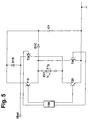
- FIG. 5 a circuit arrangement according to FIG. 5 is special advantageous. Such an arrangement is usually called Designated H-bridge circuit.
- the exemplary embodiment is only a consumer EV1 shown.
- the consumer is on with his first connection Switching means T15 with a first connection of a Capacitor C1 connected.
- the first connection is also available of the consumer EV1 via a switching device T45 with mass in Connection.
- the second connection of the consumer EV1 is via a switching device T25 with ground and via a Switching means T35 with a supply voltage Ubat in Connection.
- the supply voltage Ubat is also via a diode D1B in contact with capacitor C1.
- the cathodes of the diodes D1B and D1C are each connected to the first port of the Capacitor C1 connected.
- the second connection of the Capacitor C1 is in contact with ground.
- the switching means T35 and T45 corresponds to its function Switching means T1 in the embodiment according to FIG. 4.
- a particularly advantageous embodiment results if the diode D1B corresponding to that in Figure 4 between the Supply voltage and the first connection of the consumer is arranged.
- a shared memory can be used for all consumers
- an injection occurs when the controlling solenoid valve closed is.
- the overclocking takes place such that the valve is in its open position remains or moves to its open position. This means the overclocking takes place so that the current flow Converts consumers to a safe state.
- the flow of electricity through the consumer is at times when he is controlled so that he is in a safe Condition, released and interrupted several times, the one that is released when the current flow is interrupted Energy is stored in a capacitor.
- the flow of electricity will release such that the consumer in his safe condition Remains. This means control is so short that it is not sufficient for switching, or the Electricity flows in a direction that the consumer in his holds a secure position.
Landscapes
- Engineering & Computer Science (AREA)
- Physics & Mathematics (AREA)
- Electromagnetism (AREA)
- Chemical & Material Sciences (AREA)
- Combustion & Propulsion (AREA)
- Mechanical Engineering (AREA)
- General Engineering & Computer Science (AREA)
- Power Engineering (AREA)
- Electronic Switches (AREA)
- Charge And Discharge Circuits For Batteries Or The Like (AREA)
- Rectifiers (AREA)
- Keying Circuit Devices (AREA)
Applications Claiming Priority (2)
| Application Number | Priority Date | Filing Date | Title |
|---|---|---|---|
| DE19812744 | 1998-03-24 | ||
| DE1998112744 DE19812744A1 (de) | 1998-03-24 | 1998-03-24 | Verfahren und Vorrichtung zum Schalten eines induktiven Verbrauchers |
Publications (3)
| Publication Number | Publication Date |
|---|---|
| EP0945609A2 true EP0945609A2 (fr) | 1999-09-29 |
| EP0945609A3 EP0945609A3 (fr) | 2000-08-30 |
| EP0945609B1 EP0945609B1 (fr) | 2006-06-07 |
Family
ID=7862007
Family Applications (1)
| Application Number | Title | Priority Date | Filing Date |
|---|---|---|---|
| EP98117685A Expired - Lifetime EP0945609B1 (fr) | 1998-03-24 | 1998-09-17 | Méthode et dispositif pour commuter une charge inductive |
Country Status (3)
| Country | Link |
|---|---|
| EP (1) | EP0945609B1 (fr) |
| JP (1) | JPH11329832A (fr) |
| DE (2) | DE19812744A1 (fr) |
Cited By (1)
| Publication number | Priority date | Publication date | Assignee | Title |
|---|---|---|---|---|
| EP1296024B1 (fr) * | 2001-09-20 | 2010-06-23 | Magneti Marelli S.p.A. | Méthode de commande des actionneurs électromagnétiques pour le contrôle d'une pluralité de soupapes d'un moteur à combustion interne |
Families Citing this family (1)
| Publication number | Priority date | Publication date | Assignee | Title |
|---|---|---|---|---|
| DE19922485B4 (de) * | 1999-05-15 | 2008-06-12 | Robert Bosch Gmbh | Verfahren und Schaltungsanordnung zur Ansteuerung eines Doppelspulen-Hochdruckeinspritzmagnetventils für die Kraftstoffeinspritzung |
Citations (1)
| Publication number | Priority date | Publication date | Assignee | Title |
|---|---|---|---|---|
| DE19539071A1 (de) | 1995-03-02 | 1996-09-05 | Bosch Gmbh Robert | Vorrichtung zur Ansteuerung wenigstens eines elektromagnetischen Verbrauchers |
Family Cites Families (6)
| Publication number | Priority date | Publication date | Assignee | Title |
|---|---|---|---|---|
| JPS5661106A (en) * | 1979-10-24 | 1981-05-26 | Kokusai Gijutsu Kaihatsu Kk | Driving circuit for electromagnetic |
| FR2538942B1 (fr) * | 1982-12-29 | 1989-05-05 | Renault | Dispositif de commande d'organe(s) electromagnetique(s) a actionnement rapide, tel(s) qu'electrovanne(s) ou injecteur(s) |
| DE3702680A1 (de) * | 1986-02-18 | 1987-10-29 | Bosch Gmbh Robert | Verfahren und schaltung zur ansteuerung von elektromagnetischen verbrauchern |
| IT1223872B (it) * | 1988-10-27 | 1990-09-29 | Marelli Autronica | Circuito per il pilotaggio di un carico induttivo in particolare per il comando degli elettroiniettori di un motore a ciclo diesel |
| EP0512121B1 (fr) * | 1990-11-22 | 1997-10-01 | Kabushikigaisha Sekogiken | Regulateur de courant pour charge inductive |
| IT1261360B (it) * | 1993-11-19 | 1996-05-20 | Fiat Ricerche | Sistema elettronico per il controllo di carichi induttivi di iniettoridi un impianto di alimentazione per motori a combustione interna |
-
1998
- 1998-03-24 DE DE1998112744 patent/DE19812744A1/de not_active Withdrawn
- 1998-09-17 DE DE59813582T patent/DE59813582D1/de not_active Expired - Fee Related
- 1998-09-17 EP EP98117685A patent/EP0945609B1/fr not_active Expired - Lifetime
-
1999
- 1999-03-23 JP JP7867599A patent/JPH11329832A/ja active Pending
Patent Citations (1)
| Publication number | Priority date | Publication date | Assignee | Title |
|---|---|---|---|---|
| DE19539071A1 (de) | 1995-03-02 | 1996-09-05 | Bosch Gmbh Robert | Vorrichtung zur Ansteuerung wenigstens eines elektromagnetischen Verbrauchers |
Cited By (1)
| Publication number | Priority date | Publication date | Assignee | Title |
|---|---|---|---|---|
| EP1296024B1 (fr) * | 2001-09-20 | 2010-06-23 | Magneti Marelli S.p.A. | Méthode de commande des actionneurs électromagnétiques pour le contrôle d'une pluralité de soupapes d'un moteur à combustion interne |
Also Published As
| Publication number | Publication date |
|---|---|
| DE59813582D1 (de) | 2006-07-20 |
| JPH11329832A (ja) | 1999-11-30 |
| EP0945609B1 (fr) | 2006-06-07 |
| DE19812744A1 (de) | 1999-09-30 |
| EP0945609A3 (fr) | 2000-08-30 |
Similar Documents
| Publication | Publication Date | Title |
|---|---|---|
| EP0985814B1 (fr) | Méthode et dispositif pour commander au moins une soupape éléctromagnétique | |
| EP0704097B1 (fr) | Procede et dispositif de commande de consommateurs electromagnetiques | |
| DE102010050724B4 (de) | Fahrzeugmotor-Steuersystem | |
| EP0812461B1 (fr) | Dispositif servant a la commande d'au moins un consommateur electromagnetique | |
| DE19539071A1 (de) | Vorrichtung zur Ansteuerung wenigstens eines elektromagnetischen Verbrauchers | |
| EP1099260B1 (fr) | Procede et dispositif pour commander au moins un actionneur capacitif | |
| DE19728221A1 (de) | Verfahren und Apparat zum Hochgeschwindigkeits-Treiben einer elektromagnetischen Last | |
| WO2000009867A1 (fr) | Dispositif pour commander un appareil de reglage | |
| DE60011993T2 (de) | Apparat und Methode für das Ermitteln einer Verringerung der Kapazität während des Antriebes von piezoelektrischen Elementen | |
| DE19808780A1 (de) | Verfahren und Vorrichtung zur Ansteuerung eines Verbrauchers | |
| DE19634342A1 (de) | Vorrichtung zur Ansteuerung wenigstens zweier elektromagnetischer Verbraucher | |
| DE19735560B4 (de) | Verfahren und Vorrichtung zur Steuerung eines Verbrauchers | |
| DE102013220613B4 (de) | Verfahren und Computerprogramm zum Ansteuern eines Kraftstoffinjektors | |
| DE19821561A1 (de) | Verfahren und Vorrichtung zur Ansteuerung eines elektromagnetischen Verbrauchers | |
| EP0693756A1 (fr) | Procédé et dispositif d'excitation d'un consommateur électromagnétique | |
| DE3322006A1 (de) | Vorrichtung zur steuerung eines induktiven stellgliedes, insbesondere eines vergasers | |
| EP0945609A2 (fr) | Méthode et dispositif pour commuter une charge inductive | |
| DE3904605C2 (fr) | ||
| EP0889223B1 (fr) | Procédé et dispositif pour détecter l'instant de commutation d'une électrovalve | |
| EP1103710A2 (fr) | Méthode et dispositif pour contrôler une charge | |
| WO2000017943A1 (fr) | Circuit de decharge pour element de reglage capacitif | |
| EP0854281B1 (fr) | Dispositif de pilotage d'au moins un consommateur électromagnetique | |
| EP1375882B1 (fr) | Procédé de fonctionnement d'un moteur à combustion interne, en particulier d'automobile | |
| DE69323093T2 (de) | Ein batterieladeverfahren | |
| DE19746980A1 (de) | Verfahren und Vorrichtung zur Ansteuerung wenigstens eines elektromagnetischen Verbrauchers |
Legal Events
| Date | Code | Title | Description |
|---|---|---|---|
| PUAI | Public reference made under article 153(3) epc to a published international application that has entered the european phase |
Free format text: ORIGINAL CODE: 0009012 |
|
| AK | Designated contracting states |
Kind code of ref document: A2 Designated state(s): DE FR GB |
|
| AX | Request for extension of the european patent |
Free format text: AL;LT;LV;MK;RO;SI |
|
| PUAL | Search report despatched |
Free format text: ORIGINAL CODE: 0009013 |
|
| AK | Designated contracting states |
Kind code of ref document: A3 Designated state(s): AT BE CH CY DE DK ES FI FR GB GR IE IT LI LU MC NL PT SE |
|
| AX | Request for extension of the european patent |
Free format text: AL;LT;LV;MK;RO;SI |
|
| 17P | Request for examination filed |
Effective date: 20010228 |
|
| AKX | Designation fees paid |
Free format text: DE FR GB |
|
| 17Q | First examination report despatched |
Effective date: 20030530 |
|
| GRAP | Despatch of communication of intention to grant a patent |
Free format text: ORIGINAL CODE: EPIDOSNIGR1 |
|
| GRAS | Grant fee paid |
Free format text: ORIGINAL CODE: EPIDOSNIGR3 |
|
| GRAA | (expected) grant |
Free format text: ORIGINAL CODE: 0009210 |
|
| AK | Designated contracting states |
Kind code of ref document: B1 Designated state(s): DE FR GB |
|
| REG | Reference to a national code |
Ref country code: GB Ref legal event code: FG4D Free format text: NOT ENGLISH |
|
| REF | Corresponds to: |
Ref document number: 59813582 Country of ref document: DE Date of ref document: 20060720 Kind code of ref document: P |
|
| GBT | Gb: translation of ep patent filed (gb section 77(6)(a)/1977) |
Effective date: 20060927 |
|
| ET | Fr: translation filed | ||
| PLBE | No opposition filed within time limit |
Free format text: ORIGINAL CODE: 0009261 |
|
| STAA | Information on the status of an ep patent application or granted ep patent |
Free format text: STATUS: NO OPPOSITION FILED WITHIN TIME LIMIT |
|
| 26N | No opposition filed |
Effective date: 20070308 |
|
| PGFP | Annual fee paid to national office [announced via postgrant information from national office to epo] |
Ref country code: DE Payment date: 20071126 Year of fee payment: 10 |
|
| PGFP | Annual fee paid to national office [announced via postgrant information from national office to epo] |
Ref country code: FR Payment date: 20080917 Year of fee payment: 11 |
|
| PGFP | Annual fee paid to national office [announced via postgrant information from national office to epo] |
Ref country code: GB Payment date: 20080922 Year of fee payment: 11 |
|
| PG25 | Lapsed in a contracting state [announced via postgrant information from national office to epo] |
Ref country code: DE Free format text: LAPSE BECAUSE OF NON-PAYMENT OF DUE FEES Effective date: 20090401 |
|
| GBPC | Gb: european patent ceased through non-payment of renewal fee |
Effective date: 20090917 |
|
| REG | Reference to a national code |
Ref country code: FR Ref legal event code: ST Effective date: 20100531 |
|
| PG25 | Lapsed in a contracting state [announced via postgrant information from national office to epo] |
Ref country code: FR Free format text: LAPSE BECAUSE OF NON-PAYMENT OF DUE FEES Effective date: 20090930 |
|
| PG25 | Lapsed in a contracting state [announced via postgrant information from national office to epo] |
Ref country code: GB Free format text: LAPSE BECAUSE OF NON-PAYMENT OF DUE FEES Effective date: 20090917 |