EP0945669A2 - Projecteur pour véhicule automobile et procédé de fabrication de celui-ci - Google Patents
Projecteur pour véhicule automobile et procédé de fabrication de celui-ci Download PDFInfo
- Publication number
- EP0945669A2 EP0945669A2 EP99105416A EP99105416A EP0945669A2 EP 0945669 A2 EP0945669 A2 EP 0945669A2 EP 99105416 A EP99105416 A EP 99105416A EP 99105416 A EP99105416 A EP 99105416A EP 0945669 A2 EP0945669 A2 EP 0945669A2
- Authority
- EP
- European Patent Office
- Prior art keywords
- lens
- ventilation
- housing
- edge
- ventilation opening
- Prior art date
- Legal status (The legal status is an assumption and is not a legal conclusion. Google has not performed a legal analysis and makes no representation as to the accuracy of the status listed.)
- Withdrawn
Links
Images

Classifications
-
- F—MECHANICAL ENGINEERING; LIGHTING; HEATING; WEAPONS; BLASTING
- F21—LIGHTING
- F21S—NON-PORTABLE LIGHTING DEVICES; SYSTEMS THEREOF; VEHICLE LIGHTING DEVICES SPECIALLY ADAPTED FOR VEHICLE EXTERIORS
- F21S45/00—Arrangements within vehicle lighting devices specially adapted for vehicle exteriors, for purposes other than emission or distribution of light
- F21S45/30—Ventilation or drainage of lighting devices
- F21S45/33—Ventilation or drainage of lighting devices specially adapted for headlamps
Definitions
- the invention relates to a headlight for motor vehicles with a through Housing and an inner space formed by the lens covering the housing, in which at least one light source is arranged with at least one Interior connecting with the surroundings of the headlamp, in one Edge area of the housing arranged ventilation channel, one to the Interior facing inner ventilation opening and one to the environment has facing outer ventilation opening.
- the invention further relates to a method for producing a headlight according to claim 1.
- DE 34 24 205 A1 describes a vehicle lamp with a housing and a the lens covering the housing is known, ventilation openings in an edge region between the housing and the lens are arranged. Is between an inner ventilation opening and an outer ventilation opening a ventilation duct is formed which has vertical and horizontal duct sections.
- the disadvantage of this vehicle lamp is that for ventilation of the same additional space is required.
- DE 195 24 163 A1 describes a motor vehicle lamp with a housing and known a lens, with a ventilation channel in an edge area of the housing extends.
- the ventilation duct is separated by a between the Edge of the housing and the lens introduced sealing profile formed that at least one inner ventilation opening facing the interior and one closed has outside ventilation opening facing the environment.
- Disadvantage of the known vehicle lamp is that to form the ventilation channel additional component is required. With training as a sealing profile the danger that with increasing aging of the same water in the interior of the Light can penetrate.
- Another disadvantage is that the edge tab of the housing must be angled so that an increased space requirement for the same Illumination intensity is given.
- the object of the present invention is therefore a headlight for Motor vehicles and a method for producing such a headlight to be specified so that effective ventilation in a housing-side area the interior is guaranteed without the need for an additional building.
- the headlight according to the invention is thereby to achieve this object characterized in that the ventilation channel on the edge of the lens or on is molded onto the housing and is substantially perpendicular to Light exit surface of the lens extends, at least a portion of the Outer wall of the ventilation duct cohesively with a corresponding one Edge tab of the housing or the lens is connected.
- the ventilation duct with either Housing or with the lens is formed as a one-piece building. It is the ventilation duct in a receptacle of the other component saves space arranged.
- An area of the outer wall of the ventilation duct serves as Surface for the integral connection of the housing with the lens.
- the ventilation channel is on the lens molded.
- the corresponding edge area of the housing is a groove formed by the method according to the invention with an adhesive is filled, in an area corresponding to the ventilation duct a puncture pin protrudes from the adhesive bed of the groove.
- To assemble the The headlamp is placed on the lens with the outer ventilation opening Piercing pin placed and moved towards the base of the pin, see above that this is cut to form an opening through which the Ventilation duct with an end area on a rear of the housing edge is moved.
- In one end position of the ventilation duct is a The outer surface section of the same is completely surrounded by the adhesive. This ensures permanent and safe storage of the ventilation duct realized.
- the lens and the housing each have a circumferential edge tab, which is spaced apart extend parallel to each other and connected to each other by means of an adhesive are.
- a ventilation duct is formed on the lens and is located in one Recess of the edge tab of the housing a recording.
- the inner ventilation opening is inclined to the longitudinal axis of the ventilation duct erected so that a homogeneous Deflection of the air flow from the interior into the ventilation duct or vice versa is made possible.
- the provision of a Air guiding element with a distance to the light exit surface of the lens additional air discharge duct is formed, which is located directly on the inside Ventilation duct connects. This creates a targeted air flow and a allows more effective defrosting.
- the air guiding element can be used as a cover Decorative and covering function for headlights with an "optics-free" lens to serve.
- the invention is used in both headlights and lamps for trucks where it matters, a defrosting of the in the To cause water to penetrate the interior or to fog up To prevent lens.
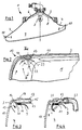
- a headlight (1) has a housing (2) and a Housing covering lens (3), which together an interior (4) form. Inside the interior (4) there is one in the rear area Light source (5) arranged in a recess of the housing (2) is.
- the housing (2) preferably has a rear stable section (6) and an adjoining front section (7) made of a plastic.
- the rear section (6) has a reflector (8) on its inside.
- Of the front section (7) is designed as a panel and extends below Broadening forward in a horizontal plane towards the lens (3).
- the front housing section (7) has a circumferential edge Edge tab (9) on which a corresponding edge tab (10) of the lens (3) is assigned.
- an adhesive (11) is applied to the outside of the edge tab (9). Subsequently, the lens (3) with its edge tabs (10) from the outside onto the Edge tabs (9) placed so that after a sufficient curing time Lens (3) is integrally connected to the housing (2).
- the lens (3) in an edge region (12) has a ventilation channel (13) which is cylindrical from an inner ventilation opening (14) facing the interior (4), one of the The outer ventilation opening (15) facing the headlight (1) extends.
- the ventilation duct (13) is connected in one piece to the lens (3) and is made by injection molding a transparent plastic, preferably Polycarbonate. The fact that a wall of the ventilation duct (13) with an edge section (16) of the lens (3) coincides Ventilation channel (13) in an outermost edge area of the lens (3) positioned.
- the Opening direction of the inner ventilation opening (14) is preferably to the shape adapted to a light exit surface (18) of the lens (3).
- the injection mold Have slider not shown, which moves in the demolding direction (19) becomes.
- the resulting edges can be formed by forming a Manufacturer logos can be concealed in a field (44).
- a stop (20) on the edge of the Edge tab (9) abuts and seals the interior (4), so that a permanent undesired penetration of gases exposed by the adhesive (11) is prevented.
- an air guide element (21) can connect to the stop (20), the air guide element (21) is preferably molded onto the stop (20) and extends at a distance of 3 to 5 mm substantially parallel to the Light exit surface (18).
- the free end of the air guide element (21) extends easy opening to the light exit surface (18), so that a homogeneous air flow is passed from the interior (4) into the ventilation duct (13).
- the Ventilation duct (13) is with a shell section in a trough-shaped Recording (22) of the housing edge (2) stored and closes with the upper edge of the edge tab (9) of the housing (2) from flush.
- a flexible approach (23) can be slipped on, so that the Air can be directed to a given location.
- a peripheral edge (24) of the housing (2) fork-like as a groove (25) be trained.
- This groove (25) is filled with the adhesive (11) and serves thus as an adhesive bed in which the edge tab (10) of the lens (3) engages integral connection of the lens (3) with the housing (2).
- a thin piercing pin (26) extends in the groove (25), which preferably protrudes centrally from the bottom of the groove (25).
- the piercing pin (26) has such a height that it does not fall in a region of the tip (27) the adhesive is covered.
- the flexible piercing pin (26) sealing the external ventilation opening (15) taken and in a floor area cut it until the ventilation duct (13) abuts a stop (29) comes into contact with a groove (30) of the groove (25) in an end position.
- the piercing pin (26) is preferably conical and has a length extending stop ribs (31) so that the ventilation channel (13) in one specified position can be placed on the piercing pin (26).
- a central jacket section of the ventilation duct (13) serves as Adhesive surface, the adhesive (11) extending from the bottom of the groove (25) to the stop (29) extends.
- the stop (29) is preferably annular or arranged on an inner side in sections, so that from the Gases escaping from adhesive do not penetrate into the interior (4) can.
- the ventilation duct (13) extends approximately in the end position with a half on a back of the groove (25).
- the other half of the Ventilation channel (13) extends essentially within the groove (25).
- One of those Interior (4) facing end region of the ventilation duct (13) extends above the groove (25).
- An air guiding element (32) can preferably be attached to the inner ventilation opening (14). be formed, which is at a distance of about 5 mm from the light exit surface (18) extends and is designed to open slightly in a free end region, so that a desired defrosting air flow in the direction of Ventilation channel (13) is generated according to the arrows (33).
- a ventilation channel (36) can be formed in an edge area (34) of a housing (35) a ventilation channel (36) can be formed.
- This Ventilation channel (36) also has an outer ventilation opening (37) on which a corresponding approach (23) is set up.
- On the opposite side is an inner ventilation opening (38) through which one by means of a Air flow element (39) flows into the ventilation duct (36) can.
- On a side of an end section (40) facing away from the interior (4) Ventilation channel (36) extends parallel to a longitudinal axis (41) of the Ventilation channel (36) a leg (42) to form a groove (43).
- This groove (43) forms an adhesive bed for receiving the edge tab (10) of the lens (3).
- the ventilation channels described above are preferably in an upper one Edge area of the housing (2) or the lens (3) arranged. They serve in essential for discharging an air flow from the interior (4) into the Surrounding the headlamp (1). In addition is in an area not shown of the housing, preferably in a rear area thereof Ventilation opening or channel arranged through the air from the environment in the Interior (4) can penetrate. In cooperation with the one described above Ventilation duct can thus provide ventilation within the interior (4) be made possible, in particular a moisture fitting in one of the Light source (3) distant edge area of the housing (2) or the lens (3) is prevented.
- the lens (3) with the housing (2) can also be passed through Welding. It is essential that a ventilation duct in an outermost edge area adapting it to the given one Shape of the lens is provided.
Landscapes
- Engineering & Computer Science (AREA)
- General Engineering & Computer Science (AREA)
- Non-Portable Lighting Devices Or Systems Thereof (AREA)
Applications Claiming Priority (2)
| Application Number | Priority Date | Filing Date | Title |
|---|---|---|---|
| DE19813294A DE19813294C1 (de) | 1998-03-26 | 1998-03-26 | Belüftungsvorrichtung an einem Kraftfahrzeugscheinwerfer und Verfahren zur Herstellung einer Belüftungsvorrichtung an einem Kraftfahrzeugscheinwerfer |
| DE19813294 | 1998-03-26 |
Publications (2)
| Publication Number | Publication Date |
|---|---|
| EP0945669A2 true EP0945669A2 (fr) | 1999-09-29 |
| EP0945669A3 EP0945669A3 (fr) | 2000-07-05 |
Family
ID=7862372
Family Applications (1)
| Application Number | Title | Priority Date | Filing Date |
|---|---|---|---|
| EP99105416A Withdrawn EP0945669A3 (fr) | 1998-03-26 | 1999-03-17 | Projecteur pour véhicule automobile et procédé de fabrication de celui-ci |
Country Status (2)
| Country | Link |
|---|---|
| EP (1) | EP0945669A3 (fr) |
| DE (1) | DE19813294C1 (fr) |
Families Citing this family (7)
| Publication number | Priority date | Publication date | Assignee | Title |
|---|---|---|---|---|
| FR2958009B1 (fr) * | 2010-03-29 | 2015-07-17 | Peugeot Citroen Automobiles Sa | Bloc optique de vehicule comprenant un canal de ventilation |
| FR2979414B1 (fr) * | 2011-08-29 | 2014-09-12 | Valeo Vision | Element transparent pour dispositif d'eclairage et/ou de signalisation, comprenant un orifice de passage d'air |
| DE102016116137A1 (de) | 2016-08-30 | 2018-03-01 | HELLA GmbH & Co. KGaA | Verfahren und Vorrichtung zum Fügen einer Lichtscheibe mit einem Gehäuse einer Beleuchtungseinrichtung für ein Kraftfahrzeug |
| DE102016116122A1 (de) * | 2016-08-30 | 2018-03-01 | HELLA GmbH & Co. KGaA | Verfahren zum Fügen einer Lichtscheibe mit einem Gehäuse einer Beleuchtungseinrichtung |
| DE102016116131A1 (de) | 2016-08-30 | 2018-03-01 | HELLA GmbH & Co. KGaA | Vorrichtung und Verfahren zum Fügen einer Lichtscheibe mit einem Gehäuse einer Beleuchtungseinrichtung eines Kraftfahrzeugs |
| DE102016116141A1 (de) | 2016-08-30 | 2018-03-01 | HELLA GmbH & Co. KGaA | Vorrichtung zum Fügen einer Lichtscheibe mit einem Gehäuse einer Beleuchtungseinrichtung eines Kraftfahrzeugs |
| DE102016224099A1 (de) | 2016-12-05 | 2018-06-07 | Volkswagen Aktiengesellschaft | Beleuchtungsvorrichtung für ein Kraftfahrzeug |
Citations (3)
| Publication number | Priority date | Publication date | Assignee | Title |
|---|---|---|---|---|
| DE3424205A1 (de) | 1984-06-30 | 1986-01-23 | Westfälische Metall Industrie KG Hueck & Co, 4780 Lippstadt | Fahrzeugleuchte |
| DE4318848A1 (de) | 1992-07-10 | 1994-01-13 | Hella Kg Hueck & Co | Leuchte für Fahrzeuge |
| DE19524163A1 (de) | 1995-07-03 | 1997-01-30 | Daimler Benz Ag | Anordnung für eine Kraftfahrzeugleuchte |
Family Cites Families (1)
| Publication number | Priority date | Publication date | Assignee | Title |
|---|---|---|---|---|
| FR2751727B1 (fr) * | 1996-07-29 | 1998-10-23 | Valeo Vision | Dispositif d'eclairage ou de signalisation pour vehicule automobile integrant un dispositif de ventilation |
-
1998
- 1998-03-26 DE DE19813294A patent/DE19813294C1/de not_active Expired - Lifetime
-
1999
- 1999-03-17 EP EP99105416A patent/EP0945669A3/fr not_active Withdrawn
Patent Citations (3)
| Publication number | Priority date | Publication date | Assignee | Title |
|---|---|---|---|---|
| DE3424205A1 (de) | 1984-06-30 | 1986-01-23 | Westfälische Metall Industrie KG Hueck & Co, 4780 Lippstadt | Fahrzeugleuchte |
| DE4318848A1 (de) | 1992-07-10 | 1994-01-13 | Hella Kg Hueck & Co | Leuchte für Fahrzeuge |
| DE19524163A1 (de) | 1995-07-03 | 1997-01-30 | Daimler Benz Ag | Anordnung für eine Kraftfahrzeugleuchte |
Also Published As
| Publication number | Publication date |
|---|---|
| DE19813294C1 (de) | 1999-08-26 |
| EP0945669A3 (fr) | 2000-07-05 |
Similar Documents
| Publication | Publication Date | Title |
|---|---|---|
| EP2287042A1 (fr) | Dispositif d'éclairage pour un habitacle de véhicule | |
| DE2926305A1 (de) | Vorrichtung zur reinigung von scheinwerferscheiben fuer kraftfahrzeuge | |
| DE19726328A1 (de) | Beleuchtungseinrichtung für Fahrzeuge | |
| DE3512882C2 (fr) | ||
| DE19813294C1 (de) | Belüftungsvorrichtung an einem Kraftfahrzeugscheinwerfer und Verfahren zur Herstellung einer Belüftungsvorrichtung an einem Kraftfahrzeugscheinwerfer | |
| WO2009003553A1 (fr) | Véhicule automobile avec une colonne a | |
| DE19636029C1 (de) | Frontleuchteneinheit für ein Kraftfahrzeug | |
| DE19546271B4 (de) | Scheinwerfer für Fahrzeuge mit einem verschwenkbaren Reflektor | |
| EP0838368A2 (fr) | Phare de véhicule | |
| DE69400548T2 (de) | Zusatzwarnleuchte für Fahrzeuge | |
| DE3227886C2 (de) | Antibeschlagvorrichtung für die hinteren Seitenscheiben eines Kraftfahrzeugs | |
| EP0879735A2 (fr) | Feux en particulier feux arrières pour véhicule | |
| EP0317896A1 (fr) | Phare pour véhicules | |
| EP0672836B1 (fr) | Dispositif de fixation | |
| DE3424205C2 (de) | Fahrzeugleuchte | |
| DE10116468A1 (de) | Leuchte | |
| DE102004025232A1 (de) | Befestigungsvorrichtung für eine Zierleiste | |
| DE69716824T2 (de) | Fahrzeugbeleuchtungs- oder Signaleinrichtung mit eingespritzter Dichtung | |
| DE69310266T2 (de) | Scheinwerfer mit verbesserter Belüftungsvorrichtung insbesondere für Kraftfahrzeuge | |
| EP0696703A1 (fr) | Phare de véhicule | |
| DE3734407C2 (fr) | ||
| DE29602125U1 (de) | Signalleuchte für Fahrzeuge | |
| DE10353374A1 (de) | Befestigungsanordnung für einen Scheinwerfer an einem Fahrzeug | |
| DE102010062967B4 (de) | Fig.Befestigungsdübel für ein Verkleidungsteil und Verkleidungsteilanordnung mit Befestigungsdübel | |
| DE19757927C1 (de) | Signalleuchte für Fahrzeuge |
Legal Events
| Date | Code | Title | Description |
|---|---|---|---|
| PUAI | Public reference made under article 153(3) epc to a published international application that has entered the european phase |
Free format text: ORIGINAL CODE: 0009012 |
|
| AK | Designated contracting states |
Kind code of ref document: A2 Designated state(s): DE ES FR GB IT |
|
| AX | Request for extension of the european patent |
Free format text: AL;LT;LV;MK;RO;SI PAYMENT 19990401 |
|
| PUAL | Search report despatched |
Free format text: ORIGINAL CODE: 0009013 |
|
| AK | Designated contracting states |
Kind code of ref document: A3 Designated state(s): AT BE CH CY DE DK ES FI FR GB GR IE IT LI LU MC NL PT SE |
|
| AX | Request for extension of the european patent |
Free format text: AL;LT;LV;MK;RO;SI PAYMENT 19990401 |
|
| 17P | Request for examination filed |
Effective date: 20001026 |
|
| AKX | Designation fees paid |
Free format text: DE ES FR GB IT |
|
| AXX | Extension fees paid |
Free format text: SI PAYMENT 19990401 |
|
| RAP1 | Party data changed (applicant data changed or rights of an application transferred) |
Owner name: HELLA KGAA HUECK & CO. |
|
| STAA | Information on the status of an ep patent application or granted ep patent |
Free format text: STATUS: THE APPLICATION IS DEEMED TO BE WITHDRAWN |
|
| 18D | Application deemed to be withdrawn |
Effective date: 20051001 |