EP0945672B1 - Signalleuchte für Kraftfahrzeug - Google Patents
Signalleuchte für Kraftfahrzeug Download PDFInfo
- Publication number
- EP0945672B1 EP0945672B1 EP99400655A EP99400655A EP0945672B1 EP 0945672 B1 EP0945672 B1 EP 0945672B1 EP 99400655 A EP99400655 A EP 99400655A EP 99400655 A EP99400655 A EP 99400655A EP 0945672 B1 EP0945672 B1 EP 0945672B1
- Authority
- EP
- European Patent Office
- Prior art keywords
- screen
- ribs
- motor vehicle
- lamp
- signal light
- Prior art date
- Legal status (The legal status is an assumption and is not a legal conclusion. Google has not performed a legal analysis and makes no representation as to the accuracy of the status listed.)
- Expired - Lifetime
Links
Images
Classifications
-
- F—MECHANICAL ENGINEERING; LIGHTING; HEATING; WEAPONS; BLASTING
- F21—LIGHTING
- F21S—NON-PORTABLE LIGHTING DEVICES; SYSTEMS THEREOF; VEHICLE LIGHTING DEVICES SPECIALLY ADAPTED FOR VEHICLE EXTERIORS
- F21S43/00—Signalling devices specially adapted for vehicle exteriors, e.g. brake lamps, direction indicator lights or reversing lights
- F21S43/20—Signalling devices specially adapted for vehicle exteriors, e.g. brake lamps, direction indicator lights or reversing lights characterised by refractors, transparent cover plates, light guides or filters
- F21S43/235—Light guides
- F21S43/247—Light guides with a single light source being coupled into the light guide
-
- F—MECHANICAL ENGINEERING; LIGHTING; HEATING; WEAPONS; BLASTING
- F21—LIGHTING
- F21S—NON-PORTABLE LIGHTING DEVICES; SYSTEMS THEREOF; VEHICLE LIGHTING DEVICES SPECIALLY ADAPTED FOR VEHICLE EXTERIORS
- F21S43/00—Signalling devices specially adapted for vehicle exteriors, e.g. brake lamps, direction indicator lights or reversing lights
- F21S43/20—Signalling devices specially adapted for vehicle exteriors, e.g. brake lamps, direction indicator lights or reversing lights characterised by refractors, transparent cover plates, light guides or filters
- F21S43/235—Light guides
- F21S43/236—Light guides characterised by the shape of the light guide
- F21S43/239—Light guides characterised by the shape of the light guide plate-shaped
-
- F—MECHANICAL ENGINEERING; LIGHTING; HEATING; WEAPONS; BLASTING
- F21—LIGHTING
- F21S—NON-PORTABLE LIGHTING DEVICES; SYSTEMS THEREOF; VEHICLE LIGHTING DEVICES SPECIALLY ADAPTED FOR VEHICLE EXTERIORS
- F21S43/00—Signalling devices specially adapted for vehicle exteriors, e.g. brake lamps, direction indicator lights or reversing lights
- F21S43/20—Signalling devices specially adapted for vehicle exteriors, e.g. brake lamps, direction indicator lights or reversing lights characterised by refractors, transparent cover plates, light guides or filters
- F21S43/235—Light guides
- F21S43/236—Light guides characterised by the shape of the light guide
- F21S43/241—Light guides characterised by the shape of the light guide of complex shape
-
- F—MECHANICAL ENGINEERING; LIGHTING; HEATING; WEAPONS; BLASTING
- F21—LIGHTING
- F21S—NON-PORTABLE LIGHTING DEVICES; SYSTEMS THEREOF; VEHICLE LIGHTING DEVICES SPECIALLY ADAPTED FOR VEHICLE EXTERIORS
- F21S43/00—Signalling devices specially adapted for vehicle exteriors, e.g. brake lamps, direction indicator lights or reversing lights
- F21S43/20—Signalling devices specially adapted for vehicle exteriors, e.g. brake lamps, direction indicator lights or reversing lights characterised by refractors, transparent cover plates, light guides or filters
- F21S43/235—Light guides
- F21S43/242—Light guides characterised by the emission area
- F21S43/245—Light guides characterised by the emission area emitting light from one or more of its major surfaces
-
- F—MECHANICAL ENGINEERING; LIGHTING; HEATING; WEAPONS; BLASTING
- F21—LIGHTING
- F21S—NON-PORTABLE LIGHTING DEVICES; SYSTEMS THEREOF; VEHICLE LIGHTING DEVICES SPECIALLY ADAPTED FOR VEHICLE EXTERIORS
- F21S43/00—Signalling devices specially adapted for vehicle exteriors, e.g. brake lamps, direction indicator lights or reversing lights
- F21S43/20—Signalling devices specially adapted for vehicle exteriors, e.g. brake lamps, direction indicator lights or reversing lights characterised by refractors, transparent cover plates, light guides or filters
- F21S43/255—Filters
Definitions
- the present invention relates to a signaling light of a motor vehicle.
- the invention relates to signal lights which generally comprise a series of lamps corresponding to the different functions, said lamps being masked by an external window made of transparent plastic material.
- the present invention is directed to a lamp of the type comprising a lamp, a reflector, a screen disposed in front of the lamp and an ice cream, the latter comprising a series of parallel colored bars with a substantially rectangular cross-section, integral with a thickness of transparent plastic material between each pair of bars of the intervals, while the screen has a flat face and on the other side, an optical clean channel light rays emitted by the lamp to the intervals.
- the fire has a uniform appearance and can nevertheless fulfill all the functions, flashing, reversing light, stop, etc ...
- the invention relates to a fire of the type defined above, the outer surface of which extends in order to extend laterally, for example, on the side of the vehicle without departing from compliance with the regulations in force.
- One of the aims of the invention is to provide a fire whose laterally extending portion of the ice is illuminated without the need to provide additional lighting means which are very difficult to accommodate in the vehicle structure.
- the invention relates to a motor vehicle signaling light of the type comprising a lamp, a reflector, a screen disposed in front of the lamp and a mirror disposed in front of the screen and which comprises a series of parallel colored bars with a substantially rectangular section, integral with a thickness of transparent plastic material by providing between each pair of bars intervals, while the screen has a flat face and, on the other side, an optical channel to channel the light rays emitted by the lamp to the intervals, said fire being characterized in that the ice has an extension for extending laterally along the vehicle, the screen having a corresponding extension, said extension of the screen having, on its side turned towards the lamp side, a series of longitudinal ribs, one end facing said lamp has an optical input surface, means being provided po To diffuse the light on the side of the face of the screen facing the ice and the right ribs.
- the means for passing the light on the side of the face of the screen facing the ice and right ribs are formed by a strip of strips corresponding to the ribs.
- the frosting of the strips increases from the inlet surface towards the free end of the ribs.
- the optical input surface is formed by a bevel oriented towards the light source.
- the face of the extension of the screen, facing the lamp comprises a series of convex gadgets, the ribs extending parallel to the right of the junction convex godrons.
- the face of the extension of the screen, facing the ice comprises a series of convex gadgets, the ribs being located at the right of the junctions of the gadroons.
- the face of the extension of the screen, turned facing the mirror comprises a series of concave cylindrical gadgets, the ribs being located at the junctions of the concave cylindrical gadgets.
- the face of the extension of the screen facing the lamp comprises a series of concave cylindrical gadroons, the ribs being located at the junctions of the concave cylindrical gadroons.
- the series of longitudinal ribs have a height that decreases from the optical input surface to the free end thereof, the face of said ribs extending the entrance surface optic being covered with a layer of a diffusing product.
- the diffusing product plays the role of a series of reflective lenses and the light can pass through the screen without the need to produce frosted strips in view of the amplification of the light intensity generated by the layer of said diffusing product.
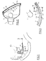
- the fire represented in FIGS. 1 and 2 has a socket 1 intended to receive a lamp 2 and a reflector 5.
- the reflector 3 is hidden by a screen 4 which is transparent and which can be, according to the different uses, colorless, or slightly colored, red, green, amber, etc.
- the screen 4 comprises, on its side 4a facing the lamp 2, a series of convex flutes 5, while the opposite face 4b is flat.
- the screen 4 is masked by an ice cream 7 which is formed of a series of parallel bars 8 of red color which are secured, by their outwardly facing face, with a thickness 9 of a colorless plastic material, a colorless interval 9a being provided between each pair of bars 8.
- the bars 8 have a substantially rectangular section and in this embodiment extend parallel horizontally, but could perfectly be located vertically.
- the light rays emitted by the lamp 2 are, thanks to the screen 4, concentrated in the intervals 9a.
- the intervals 9a are sufficiently narrow so that the observer, located next to the fire, sees only a general red appearance when the fire is off, but large enough to let in the light emitted by the lamp 2.
- the screen 4 is colorless and the white lamp 2, the light passing through the intervals 9a will be white. If we want to get a colored light, the screen 4 or the lamp 2 will be colored.
- the window 7 is provided with an extension 17 which is intended to extend on the side wall of the vehicle, the screen 4 having a corresponding extension 18.
- the extension 17 of the ice 7 is made in the same way as said ice with a series of parallel bars 8 red which are secured, by their side facing the extension 18 of the screen 4, a thickness 9 of plastic colorless, a colorless interval 9a being provided between each pair of bars 8.
- the extension 18 of the screen 4 has, on the face 4a, a series of convex gadgets 5 and the face 4b facing the ice is flat.
- the extension 18 of the screen 4 comprises a rib 20.
- Each rib 20, on the side of its end facing the lamp 2 has an optical input surface which can be formed by a bevel 21 in order to capture as much light as possible from said lamp 2.
- All the faces of the ribs 20 are perfectly polished to retain the incoming light by the bevel 21.
- the bevels of the different ribs may have different inclinations, depending on their position relative to the lamp 2.
- the part of the face 4b of the extension 18 of the screen 4 has, at the right of each rib 20, A frosted strip 22.
- these strips include a roughening which increases from the end of the extension 18 adjacent to a bevel 21 to its free end.
- the light captured in the ribs 20 will escape through the corresponding frosted strip so that the extension 17 is illuminated along its entire length.
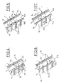
- FIG 5 there is shown an alternative embodiment in which the screen 10 which corresponds to the extension 18 of the screen 4 has, on its face 10b, facing the extension 17 of the ice 7, a series of gadroons convex 11, while the opposite face 10a facing the lamp is flat and has a series of ribs 20a parallel to each other, the gap between the gadroons 11 and located right of the ribs 20a being formed of a frosted strip 22a .
- the etching is increasing from the bevel 21 to the free end of the ribs. The light captured by the ribs 20a will escape through the frosted strips and pass through the intervals 9a.
- FIG. 6 there is shown a third embodiment of the invention.
- the screen 12 which corresponds to the extension 18 of the screen 4, on its face 12a facing the lamp 2, has a flat surface, while the other face 12b, facing the extension 17 of the 7 shows a series of concave cylindrical gadroons 13.
- the face 12a is provided with a series of ribs 20b extending parallel to the right of the junction of the concave cylindrical gadroons 13, while the junction of said gadroons, on the face 12b , is frosted to form strips 22b whose grinding is increasing from bevels 21 to the free end of said ribs 20b.
- Figure 7 shows yet another variant of the invention.
- the extension 17 of the ice 7 is of the same type as the extensions 17 of the various previous figures.
- the extension 18 of the screen 4 designated by the reference 14 has a face 14a with a series of concave cylindrical gadgets 15 turned on the side of the lamp and a plane face 14b.
- the ribs 20c are located at the junctions of the gadroons 15, the face 14b having, in line with the ribs 20, frosted strips 22c whose grinding is increasing from the bevel 21 to the free end of said ribs 20c.
- the extension 17 of the ice 7 is constituted in the same manner as in the previous embodiments.
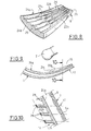
- FIGS. 8, 9 and 10 show an alternative embodiment of the invention in which the screen 24 has, on its face 24a, convex gadgets 25 and on its extension 18, on the side of the face 24a between said gadroons, ribs 20d.
- the face 24b of the screen 24, in this embodiment, does not include frosted strips, but it could well conform.
- Each rib 20d has, on the side of its end facing the lamp 2, a bevel 21a, and the height of each said rib 20d decreases from the rib to its free end.
- the bevels 21a are optical input surfaces which are intended to capture as much light as possible from the lamp 2.
- the face of the ribs 20d extending the bevels 21a is coated with a layer of a diffusing product such as white paint 26.
- this painting is a multitude of reflective lenses that return light through the face 24b, along the lines corresponding to the ribs 20d.
- the extension 17 of the ice 7 is made in the same way as in the other embodiments.
Landscapes
- Engineering & Computer Science (AREA)
- General Engineering & Computer Science (AREA)
- Non-Portable Lighting Devices Or Systems Thereof (AREA)
Claims (10)
- Signalleuchte für ein Kraftfahrzeug jener Art, die eine Lampe (2), einen Reflektor (3), einen vor der Lampe (2) angeordneten Schirm (4) und eine vor dem Schirm (4) angeordnete Scheibe (7) enthält und die eine Reihe von gefärbten parallelen Stäben (8) mit im Wesentlichen rechteckigem Querschnitt aufweist, die fest mit einer durchsichtigen Kunststoffmaterialdicke verbunden sind, wobei zwischen jedem Stab-(8)Paar Zwischenräume (9a) ausgebildet sind, während der Schirm (4) eine ebene Fläche (4b) und auf der anderen Seite eine Optik aufweist, die die von der Lampe (2) abgestrahlten Lichtstrahlen zu den Zwischenräumen (9a) leitet, wobei die Scheibe (7) eine Verlängerung (17) aufweist, die sich seitlich entlang dem Fahrzeug erstrecken soll, dadurch gekennzeichnet, dass der Schirm (4) eine entsprechende Verlängerung (18) aufweist, wobei die Verlängerung (18) des Schirms (4) auf ihrer zur Lampe (2) weisenden Seite eine Reihe von Längsrippen (20) aufweist, von denen ein zur Lampe weisendes Ende eine optische Eingangsfläche (21) aufweist, wobei Mittel vorgesehen sind, um das Licht auf der Seite der zur Scheibe (7) weisenden Fläche des Schirms (4) senkrecht zu den Rippen (20) zu streuen.
- Signalleuchte für ein Kraftfahrzeug nach Anspruch 1, dadurch gekennzeichnet, dass die Mittel zum Durchlassen des Lichts auf der Seite der Fläche des Schirms (4), die zur Scheibe weist und sich senkrecht zu den Rippen (20) befindet, durch Mattschleifen von den Rippen entsprechenden Bändern gebildet werden.
- Signalleuchte für ein Kraftfahrzeug nach Anspruch 1, dadurch gekennzeichnet, dass das Mattschleifen der Bänder (22) von der optischen Eingangsfläche (21) zum freien Ende der Rippen (20) zunimmt.
- Signalleuchte für ein Kraftfahrzeug nach Anspruch 1, dadurch gekennzeichnet, dass die optische Eingangsfläche durch eine zur Lichtquelle ausgerichtete Schräge (21) gebildet wird.
- Signalleuchte für ein Kraftfahrzeug nach Anspruch 1, dadurch gekennzeichnet, dass die zur Lampe (2) weisende Fläche (4a) der Verlängerung (18) des Schirms (4) eine Reihe von konvexen Godronierungen (5) aufweist, wobei sich die Rippen (20) parallel senkrecht zur Verbindungsstelle der konvexen Godronierungen (5) erstrecken.
- Signalleuchte für ein Kraftfahrzeug nach Anspruch 1, dadurch gekennzeichnet, dass die zur Scheibe (7) weisende Fläche (10b) der Verlängerung (18) der Blende (10) eine Reihe von konvexen Godronierungen (11) aufweist, wobei sich die Rippen (20a) senkrecht zu den Verbindungsstellen der Godronierungen (11) befinden.
- Signalleuchte für ein Kraftfahrzeug nach Anspruch 1, dadurch gekennzeichnet, dass die zur Scheibe (7) weisende Fläche (12b) der Verlängerung (18) des Schirms (12) eine Reihe von zylindrischen, konkaven Godronierungen (13) aufweist, wobei sich die Rippen (20b) senkrecht zu den Verbindungsstellen der zylindrischen, konkaven Godronierungen befinden.
- Signalleuchte für ein Kraftfahrzeug nach Anspruch 1, dadurch gekennzeichnet, dass die zur Lampe (2) weisende Fläche (14a) der Verlängerung (18) des Schirms (14) eine Reihe von zylindrischen, konkaven Godronierungen (15) aufweist, wobei sich die Rippen (20c) senkrecht zu den Verbindungsstellen der zylindrischen, konkaven Godronierungen (15) befinden.
- Signalleuchte für ein Kraftfahrzeug nach den Ansprüchen 1 und 4, dadurch gekennzeichnet, dass die Reihe von Längsrippen (20d) eine Höhe aufweist, die sich von der optischen Eingangsfläche (21a) bis zu dem freien Ende davon verringert, wobei die die optische Eingangsfläche verlängernde Fläche der Rippen mit einer Streumittelschicht überzogen ist.
- Signalleuchte für ein Kraftfahrzeug nach Anspruch 9, dadurch gekennzeichnet, dass das Streumittel durch eine Weißfarbschicht gebildet wird.
Applications Claiming Priority (2)
| Application Number | Priority Date | Filing Date | Title |
|---|---|---|---|
| FR9803551A FR2776252B1 (fr) | 1998-03-23 | 1998-03-23 | Feu de signalisation de vehicule automobile |
| FR9803551 | 1998-03-23 |
Publications (2)
| Publication Number | Publication Date |
|---|---|
| EP0945672A1 EP0945672A1 (de) | 1999-09-29 |
| EP0945672B1 true EP0945672B1 (de) | 2007-07-04 |
Family
ID=9524383
Family Applications (1)
| Application Number | Title | Priority Date | Filing Date |
|---|---|---|---|
| EP99400655A Expired - Lifetime EP0945672B1 (de) | 1998-03-23 | 1999-03-17 | Signalleuchte für Kraftfahrzeug |
Country Status (4)
| Country | Link |
|---|---|
| EP (1) | EP0945672B1 (de) |
| DE (1) | DE69936414T2 (de) |
| ES (1) | ES2289801T3 (de) |
| FR (1) | FR2776252B1 (de) |
Families Citing this family (3)
| Publication number | Priority date | Publication date | Assignee | Title |
|---|---|---|---|---|
| FR2841843B1 (fr) * | 2002-07-04 | 2005-07-29 | Plastic Omnium Cie | Dispositif de signalisation et piece de carrosserie de vehicule automobile munie d'un tel dispositif |
| DE102004061692A1 (de) * | 2004-12-22 | 2006-07-06 | Daimlerchrysler Ag | Heckleuchte eines Fahrzeuges |
| DE102005040100B4 (de) | 2005-08-24 | 2022-02-03 | Bayerische Motoren Werke Aktiengesellschaft | Fahrzeugleuchte mit einem ersten Leuchtenfunktionsbereich und wenigstens einem weiteren Leuchtenfunktionsbereich in Trennbereichen zwischen durchleuchtbaren, lichtstreuende Mittel aufweisenden Leuchtkörpern für den ersten Leuchtenfunktionsbereich |
Family Cites Families (3)
| Publication number | Priority date | Publication date | Assignee | Title |
|---|---|---|---|---|
| DE3130085A1 (de) * | 1981-07-30 | 1983-02-17 | Westfälische Metall Industrie KG Hueck & Co, 4780 Lippstadt | "signalleuchte fuer fahrzeuge" |
| EP0074726B1 (de) * | 1981-08-29 | 1985-05-02 | Britax Vega Limited | Fahrzeugleuchte |
| FR2695362B1 (fr) * | 1992-09-09 | 1994-12-02 | Valeo Vision | Feu de signalisation à visibilité latérale améliorée pour véhicule automobile. |
-
1998
- 1998-03-23 FR FR9803551A patent/FR2776252B1/fr not_active Expired - Fee Related
-
1999
- 1999-03-17 EP EP99400655A patent/EP0945672B1/de not_active Expired - Lifetime
- 1999-03-17 DE DE69936414T patent/DE69936414T2/de not_active Expired - Lifetime
- 1999-03-17 ES ES99400655T patent/ES2289801T3/es not_active Expired - Lifetime
Non-Patent Citations (1)
| Title |
|---|
| None * |
Also Published As
| Publication number | Publication date |
|---|---|
| FR2776252B1 (fr) | 2000-05-19 |
| DE69936414T2 (de) | 2008-03-06 |
| EP0945672A1 (de) | 1999-09-29 |
| FR2776252A1 (fr) | 1999-09-24 |
| ES2289801T3 (es) | 2008-02-01 |
| DE69936414D1 (de) | 2007-08-16 |
Similar Documents
| Publication | Publication Date | Title |
|---|---|---|
| EP0587501B1 (de) | Kraftfahrzeug-Signalleuchte mit verbesserter seitlicher Sichtbarkeit | |
| FR2759149A1 (fr) | Projecteur pour vehicule | |
| WO2011070161A1 (fr) | Dispositif pour feu de signalisation de vehicule automobile | |
| WO2017103267A1 (fr) | Module lumineux, notamment pour feu stop de véhicule | |
| EP3482012A1 (de) | Doppelwandvorrichtung für beleuchtung | |
| EP0945672B1 (de) | Signalleuchte für Kraftfahrzeug | |
| FR2826707A1 (fr) | Dispositif d'eclairage reparti, notamment pour l'eclairage d'une cavite | |
| EP0715988B1 (de) | Rücklicht für Fahrzeuge | |
| EP0911574B1 (de) | Lichtabgabeoptik für Fahrzeugsignalleuchten | |
| EP1279890B1 (de) | Signalleuchte für ein Kraftfahrzeug | |
| EP1149732A1 (de) | Kfz-Signalleuchte | |
| CH676877A5 (de) | ||
| FR2643863A1 (fr) | Feu de signalisation d'aspect uniforme, notamment pour vehicule automobile | |
| CH657708A5 (fr) | Appareil d'eclairage. | |
| EP1387122B1 (de) | Signalleuchte für ein Kraftfahrzeug | |
| EP1467145B1 (de) | Signalleuchte für Fahrzeuge | |
| FR2770184A1 (fr) | Feu de signalisation de vehicule automobile | |
| FR2661377A1 (fr) | Feu de signalisation de vehicules automobiles. | |
| FR2675093A1 (fr) | Bloc optique a enjoliveur perfectionne, notamment pour vehicule automobile. | |
| EP0758070A1 (de) | Signalleuchte mit gleichmässigem Erscheinungsbild | |
| FR2826465A1 (fr) | Dispositif optique, notamment imageur a cristaux liquides, et miroir associe | |
| FR2759652A1 (fr) | Feu de signalisation de vehicule automobile | |
| FR2858278A3 (fr) | Dispositif d'eclairage pour une immatriculation de vehicule automobile | |
| FR2730683A1 (fr) | Perfectionnements aux feux arriere de vehicules automobiles | |
| FR2793302A1 (fr) | Feu de signalisation de vehicule |
Legal Events
| Date | Code | Title | Description |
|---|---|---|---|
| PUAI | Public reference made under article 153(3) epc to a published international application that has entered the european phase |
Free format text: ORIGINAL CODE: 0009012 |
|
| AK | Designated contracting states |
Kind code of ref document: A1 Designated state(s): DE ES FR GB IT SE |
|
| AX | Request for extension of the european patent |
Free format text: AL;LT;LV;MK;RO;SI |
|
| 17P | Request for examination filed |
Effective date: 20000107 |
|
| AKX | Designation fees paid |
Free format text: DE ES FR GB IT SE |
|
| RAP1 | Party data changed (applicant data changed or rights of an application transferred) |
Owner name: AUTOMOTIVE LIGHTING REAR FRANCE |
|
| RAP1 | Party data changed (applicant data changed or rights of an application transferred) |
Owner name: AUTOMOTIVE LIGHTING REAR LAMPS FRANCE |
|
| GRAP | Despatch of communication of intention to grant a patent |
Free format text: ORIGINAL CODE: EPIDOSNIGR1 |
|
| RIC1 | Information provided on ipc code assigned before grant |
Ipc: F21S 8/10 20060101AFI20061116BHEP |
|
| GRAS | Grant fee paid |
Free format text: ORIGINAL CODE: EPIDOSNIGR3 |
|
| GRAA | (expected) grant |
Free format text: ORIGINAL CODE: 0009210 |
|
| AK | Designated contracting states |
Kind code of ref document: B1 Designated state(s): DE ES FR GB IT SE |
|
| REG | Reference to a national code |
Ref country code: GB Ref legal event code: FG4D Free format text: NOT ENGLISH |
|
| REF | Corresponds to: |
Ref document number: 69936414 Country of ref document: DE Date of ref document: 20070816 Kind code of ref document: P |
|
| GBV | Gb: ep patent (uk) treated as always having been void in accordance with gb section 77(7)/1977 [no translation filed] |
Effective date: 20070704 |
|
| REG | Reference to a national code |
Ref country code: ES Ref legal event code: FG2A Ref document number: 2289801 Country of ref document: ES Kind code of ref document: T3 |
|
| PLBE | No opposition filed within time limit |
Free format text: ORIGINAL CODE: 0009261 |
|
| STAA | Information on the status of an ep patent application or granted ep patent |
Free format text: STATUS: NO OPPOSITION FILED WITHIN TIME LIMIT |
|
| PG25 | Lapsed in a contracting state [announced via postgrant information from national office to epo] |
Ref country code: GB Free format text: LAPSE BECAUSE OF FAILURE TO SUBMIT A TRANSLATION OF THE DESCRIPTION OR TO PAY THE FEE WITHIN THE PRESCRIBED TIME-LIMIT Effective date: 20070704 |
|
| 26N | No opposition filed |
Effective date: 20080407 |
|
| PG25 | Lapsed in a contracting state [announced via postgrant information from national office to epo] |
Ref country code: SE Free format text: LAPSE BECAUSE OF FAILURE TO SUBMIT A TRANSLATION OF THE DESCRIPTION OR TO PAY THE FEE WITHIN THE PRESCRIBED TIME-LIMIT Effective date: 20071004 |
|
| PG25 | Lapsed in a contracting state [announced via postgrant information from national office to epo] |
Ref country code: IT Free format text: LAPSE BECAUSE OF NON-PAYMENT OF DUE FEES Effective date: 20080331 |
|
| PGFP | Annual fee paid to national office [announced via postgrant information from national office to epo] |
Ref country code: ES Payment date: 20110325 Year of fee payment: 13 Ref country code: FR Payment date: 20110408 Year of fee payment: 13 Ref country code: DE Payment date: 20110325 Year of fee payment: 13 |
|
| REG | Reference to a national code |
Ref country code: FR Ref legal event code: ST Effective date: 20121130 |
|
| PG25 | Lapsed in a contracting state [announced via postgrant information from national office to epo] |
Ref country code: FR Free format text: LAPSE BECAUSE OF NON-PAYMENT OF DUE FEES Effective date: 20120402 |
|
| REG | Reference to a national code |
Ref country code: DE Ref legal event code: R119 Ref document number: 69936414 Country of ref document: DE Effective date: 20121002 |
|
| REG | Reference to a national code |
Ref country code: ES Ref legal event code: FD2A Effective date: 20130710 |
|
| PG25 | Lapsed in a contracting state [announced via postgrant information from national office to epo] |
Ref country code: ES Free format text: LAPSE BECAUSE OF NON-PAYMENT OF DUE FEES Effective date: 20120318 |
|
| PG25 | Lapsed in a contracting state [announced via postgrant information from national office to epo] |
Ref country code: DE Free format text: LAPSE BECAUSE OF NON-PAYMENT OF DUE FEES Effective date: 20121002 |