EP0945688A2 - Chaudière - Google Patents
Chaudière Download PDFInfo
- Publication number
- EP0945688A2 EP0945688A2 EP99200784A EP99200784A EP0945688A2 EP 0945688 A2 EP0945688 A2 EP 0945688A2 EP 99200784 A EP99200784 A EP 99200784A EP 99200784 A EP99200784 A EP 99200784A EP 0945688 A2 EP0945688 A2 EP 0945688A2
- Authority
- EP
- European Patent Office
- Prior art keywords
- plates
- heat exchanger
- appliance
- fluid
- heating
- Prior art date
- Legal status (The legal status is an assumption and is not a legal conclusion. Google has not performed a legal analysis and makes no representation as to the accuracy of the status listed.)
- Granted
Links
Images


Classifications
-
- F—MECHANICAL ENGINEERING; LIGHTING; HEATING; WEAPONS; BLASTING
- F28—HEAT EXCHANGE IN GENERAL
- F28D—HEAT-EXCHANGE APPARATUS, NOT PROVIDED FOR IN ANOTHER SUBCLASS, IN WHICH THE HEAT-EXCHANGE MEDIA DO NOT COME INTO DIRECT CONTACT
- F28D9/00—Heat-exchange apparatus having stationary plate-like or laminated conduit assemblies for both heat-exchange media, the media being in contact with different sides of a conduit wall
- F28D9/0081—Heat-exchange apparatus having stationary plate-like or laminated conduit assemblies for both heat-exchange media, the media being in contact with different sides of a conduit wall the conduits for one heat-exchange medium being formed by a single plate-like element ; the conduits for one heat-exchange medium being integrated in one single plate-like element
-
- F—MECHANICAL ENGINEERING; LIGHTING; HEATING; WEAPONS; BLASTING
- F24—HEATING; RANGES; VENTILATING
- F24H—FLUID HEATERS, e.g. WATER OR AIR HEATERS, HAVING HEAT-GENERATING MEANS, e.g. HEAT PUMPS, IN GENERAL
- F24H1/00—Water heaters, e.g. boilers, continuous-flow heaters or water-storage heaters
- F24H1/22—Water heaters other than continuous-flow or water-storage heaters, e.g. water heaters for central heating
- F24H1/38—Water heaters other than continuous-flow or water-storage heaters, e.g. water heaters for central heating with water contained in separate elements, e.g. radiator-type element
-
- F—MECHANICAL ENGINEERING; LIGHTING; HEATING; WEAPONS; BLASTING
- F24—HEATING; RANGES; VENTILATING
- F24H—FLUID HEATERS, e.g. WATER OR AIR HEATERS, HAVING HEAT-GENERATING MEANS, e.g. HEAT PUMPS, IN GENERAL
- F24H1/00—Water heaters, e.g. boilers, continuous-flow heaters or water-storage heaters
- F24H1/22—Water heaters other than continuous-flow or water-storage heaters, e.g. water heaters for central heating
- F24H1/40—Water heaters other than continuous-flow or water-storage heaters, e.g. water heaters for central heating with water tube or tubes
-
- F—MECHANICAL ENGINEERING; LIGHTING; HEATING; WEAPONS; BLASTING
- F24—HEATING; RANGES; VENTILATING
- F24H—FLUID HEATERS, e.g. WATER OR AIR HEATERS, HAVING HEAT-GENERATING MEANS, e.g. HEAT PUMPS, IN GENERAL
- F24H1/00—Water heaters, e.g. boilers, continuous-flow heaters or water-storage heaters
- F24H1/22—Water heaters other than continuous-flow or water-storage heaters, e.g. water heaters for central heating
- F24H1/44—Water heaters other than continuous-flow or water-storage heaters, e.g. water heaters for central heating with combinations of two or more of the types covered by groups F24H1/24 - F24H1/40
-
- F—MECHANICAL ENGINEERING; LIGHTING; HEATING; WEAPONS; BLASTING
- F24—HEATING; RANGES; VENTILATING
- F24H—FLUID HEATERS, e.g. WATER OR AIR HEATERS, HAVING HEAT-GENERATING MEANS, e.g. HEAT PUMPS, IN GENERAL
- F24H8/00—Fluid heaters characterised by means for extracting latent heat from flue gases by means of condensation
-
- F—MECHANICAL ENGINEERING; LIGHTING; HEATING; WEAPONS; BLASTING
- F28—HEAT EXCHANGE IN GENERAL
- F28D—HEAT-EXCHANGE APPARATUS, NOT PROVIDED FOR IN ANOTHER SUBCLASS, IN WHICH THE HEAT-EXCHANGE MEDIA DO NOT COME INTO DIRECT CONTACT
- F28D21/00—Heat-exchange apparatus not covered by any of the groups F28D1/00 - F28D20/00
- F28D21/0001—Recuperative heat exchangers
- F28D21/0003—Recuperative heat exchangers the heat being recuperated from exhaust gases
- F28D21/0005—Recuperative heat exchangers the heat being recuperated from exhaust gases for domestic or space-heating systems
- F28D21/0007—Water heaters
-
- F—MECHANICAL ENGINEERING; LIGHTING; HEATING; WEAPONS; BLASTING
- F24—HEATING; RANGES; VENTILATING
- F24H—FLUID HEATERS, e.g. WATER OR AIR HEATERS, HAVING HEAT-GENERATING MEANS, e.g. HEAT PUMPS, IN GENERAL
- F24H1/00—Water heaters, e.g. boilers, continuous-flow heaters or water-storage heaters
- F24H1/48—Water heaters for central heating incorporating heaters for domestic water
- F24H1/52—Water heaters for central heating incorporating heaters for domestic water incorporating heat exchangers for domestic water
-
- F—MECHANICAL ENGINEERING; LIGHTING; HEATING; WEAPONS; BLASTING
- F28—HEAT EXCHANGE IN GENERAL
- F28F—DETAILS OF HEAT-EXCHANGE AND HEAT-TRANSFER APPARATUS, OF GENERAL APPLICATION
- F28F2250/00—Arrangements for modifying the flow of the heat exchange media, e.g. flow guiding means; Particular flow patterns
- F28F2250/10—Particular pattern of flow of the heat exchange media
- F28F2250/102—Particular pattern of flow of the heat exchange media with change of flow direction
-
- Y—GENERAL TAGGING OF NEW TECHNOLOGICAL DEVELOPMENTS; GENERAL TAGGING OF CROSS-SECTIONAL TECHNOLOGIES SPANNING OVER SEVERAL SECTIONS OF THE IPC; TECHNICAL SUBJECTS COVERED BY FORMER USPC CROSS-REFERENCE ART COLLECTIONS [XRACs] AND DIGESTS
- Y02—TECHNOLOGIES OR APPLICATIONS FOR MITIGATION OR ADAPTATION AGAINST CLIMATE CHANGE
- Y02B—CLIMATE CHANGE MITIGATION TECHNOLOGIES RELATED TO BUILDINGS, e.g. HOUSING, HOUSE APPLIANCES OR RELATED END-USER APPLICATIONS
- Y02B30/00—Energy efficient heating, ventilation or air conditioning [HVAC]
Definitions
- This invention relates to a heating appliance, such as might be used in a central heating system.
- Heating appliances, or boilers, used in central heating systems include at least one heat exchanger, in which a fluid to be heated (such as water in most domestic heating systems) is in heat exchanging relationship with a heating fluid, such as gases which have been heated in a burner, especially a gas burner.
- a fluid to be heated such as water in most domestic heating systems
- a heating fluid such as gases which have been heated in a burner, especially a gas burner.
- the invention particularly but not exclusively relates to a boiler for use in a central heating system, and particularly to a condenser boiler in which cool return water is heated through energy provided by condensing water from flue gases.
- the invention also relates to a so-called combination condenser boiler which combines the principles of a condenser boiler with ability to heat incoming water to supply the hot water directly to the taps of a domestic or other building.
- the invention is also applicable to boilers in which gas and air to be burned by a burner are mixed in an inlet manifold before entering a burner manifold.
- Such appliances are known as premix appliances.
- the invention applies to appliances in which gas and air are mixed in the burner manifold.
- Heat exchangers commonly include elements for increasing the heat exchanging surfaces.
- pipes through which the fluid to be heated flows might be fitted with fins.
- a commonly used heat exchanger comprises an array of tubes for fluid which is to be heated, and an array of fins attached to the tubes.
- a secondary heat exchanger can be used to transfer heat from heating fluid discharged from a primary heat exchanger, to fluid to be heated which is supplied to the secondary heat exchanger.
- a known condenser boiler comprises a primary heat exchanger within which is positioned a burner. Water to be heated enters the boiler via a water supply conduit and is received firstly in a secondary heat exchanger. Water in the secondary heat exchanger receives heat from exhaust gases which have been used to heat water in the primary heat exchanger, and the water then passes from the secondary exchanger through the primary heat exchanger.
- Such a condenser boiler will also include a fan to control flow of gases through the appliance.
- a heating appliance for a central heating system which includes a secondary heat exchanger comprising a plurality of plates arranged in a stack, the plates having chambers extending along their length within the plates in which the fluid to be heated can flow, the heat exchanger further comprising a baffle plate positioned towards the centre of the plates and orientated substantially at right angles to the plates to divide the heat exchanger into two parts.
- Spacers may be provided by which adjacent plates in the stack are held apart, to define spaces along which a heating fluid can flow, to exchange heat with the fluid to be heated through the walls of the plates.
- the exchanger has inlet and outlet manifolds through which fluid entering and leaving the heat exchanger can communicate with the chambers in the plates to flow within the chambers from the inlet manifold to the outlet manifold and there will be an inlet and outlet for heating fluid.
- the heating appliance may further compris a primary heat exchanger.
- the heating appliance further comprises a fan for controlling the flow of fluid around the heating appliance.
- the heating appliance comprises a depression chamber in which the pressure within the chamber is held at lower than ambient pressure.
- the heat exchanger comprises a baffle plate which serves to divide the edges of the plates forming the stack and thereby separate incoming from outgoing flue gases.
- the inventor has found that, surprisingly, the presence of such a baffle plate improves gas flow within the heat exchanger and thus improves the efficiency of the heat appliance.
- the baffle plate by dividing the secondary heat exchanger, forces gases in a particular direction towards the plates.
- the chambers in the plates carry water to be heated in the heat exchanger. This creates turbulence and also a turning point in the spaces between the plates which allows high transfer of heat.
- the water inside the heating circuit passing through the secondary heat exchanger is also believed to be turbulent which also helps to achieve high heat transfer.
- the fan is positioned on the depression chamber and serves to suck gases through the primary heat exchanger.
- An advantage of thus positioning the fan is that it is believed to in a better position to cope more safely with the day to day running of the appliance due to the fact that it does not have to suck on condensed flue gases and works on the hot side of the primary heat exchanger.
- a heating appliance for a central heating system comprising:
- the dividing means preferably comprise a baffle plate.
- the heating appliance of the present invention has the advantage that it can provide efficient heat exchange, while providing an acceptably low resistance to flow of both heating fluid and fluid to be heated.
- the low resistance to flow of heating fluid is believed to arise from the fact that it can flow freely in the spaces between the plates of the secondary exchanger, without interference from fins or other members extending laterally between the plates. This free flow can be important when the heat exchanger is used as a secondary heat exchanger because of the relatively high pressure in the heating fluid on the "exit" side of the fan.
- a further advantage of the secondary heat exchanger in the appliance of the present invention is that it is capable of being manufactured conveniently. This is facilitated by forming the plates by extrusion e.g. of aluminium. This has been found to be a particularly convenient technique for forming a multi-channel conduit, in particular compared with previously used techniques in which fins have been formed separately on conduits.
- Another advantage of the present invention is that the secondary heat exchanger and the primary heat exchanger are both contained within a sealed chamber in which the pressure of the sealed chamber is maintained at significantly lower than ambient pressure. Thus, in the unlikely event of leakage from the secondary exchanger, gases pass a second time through primary exchanger and are vented out rather than leaking into the room where the boiler is located.
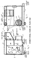
- a heating appliance in the form of a boiler for use in a domestic central heating system is designated generally by the numeral 100. It comprises a primary heat exchanger 1 and, being a "combination" boiler, a heat exchanger for tap water 2. It includes a burner 3 having an ignition electrode 9 and igniter 7, and being supplied by a modulating gas valve 12. Conventional heating controls 15 and 16 are supplied together with a water pressure switch 17 and overheat cut-off thermostat 18.
- Central heating water on the cool or 'return' side passes through compression ball valve 21 to a circulation pump 29 and thence to a secondary, condensing heat exchanger 6.
- a secondary, condensing heat exchanger 6 From the secondary heat exchanger 6 water flows to the primary heat exchanger 1 where it is heated by the gas burner 3 and proceeds to a three-way valve 24.
- the valve 24 controls whether the water is directed to the central heating system or to the heat exchanger 2 to heat in-coming cold water for the "hot" domestic taps.
- a safety pressure release system 23 is connected to the inlet for return water just upstream of the pump 29.
- a pressure gauge 30 is supplied.
- An expansion tank 37 is also connected between the valve 21 and the pump 29.
- a fan 36 is positioned above the primary heat exchanger 1 and sucks flue gases through the primary heat exchanger 1 from the burner 3 and "pushes" them into the secondary heat exchanger 6 and out to the flue via the flue connection 5.
- a vent valve 26 and air pressure valve 28 are supplied to control any build up of pressure.
- the secondary exchanger 6 condenses water 40 from the flue gases which collects in a condensate sump 22 which is in turn connected to a condensing trap 8 and thence to drain. Rather than allow a constant drip, which is susceptible to freezing in the winter, the condensing trap 8 fills before emptying in a single syphonic action.
- the chamber 38 is sealed and, by action of the fan 36, is maintained at a pressure below ambient. This is beneficial in that leakage of flue gases is less likely when the burner chamber is maintained below ambient pressure.
- the secondary heat exchanger 6 is also within the depression chamber 38 thus any leakage from the secondary exchanger does not go to atmosphere in the building but is recirculated through the primary heat exchanger and out to the flue 5.
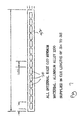
- the heat exchanger 6 comprises a stack of plates 32 in spaced apart location so as to provide spaces 33 there between.
- the plates 32 comprise a series of chambers 34 extending along their length and may be referred to as waterway tube plates.
- the ends of the chambers 34 open into an inlet manifold 42 and an outlet manifold 44 respectively.
- the inlet manifold 42 has a water inlet 46 for return water and the outlet manifold 44 has an outlet 48 for heated outlet water to go to the primary exchanger 1.
- Flue gas enters a flue gas inlet 50 and travels as shown by the arrows in figure 2 through the spaces 33 between the plates 32.
- a baffle 54 is located at right angles to the direction of the plates 32 between the inlet 50 and outlet 52 thereby forcing flue gases in the general direction shown by the arrows in figure 2.
- baffles 56 on the ends of the plates 32 in areas immediately opposite the inlet 50 and outlet 52 further turbulence in the gases is caused and this enhances heat exchange further.
- the three-way valve 24 when there is a demand for domestic hot water, e.g. when the "hot" tap is turned on, the three-way valve 24 operates to divert the hot water from the primary exchanger 1 to the heat exchanger 2. Tap water passes through the other side of the heat exchanger 2 from the cold "mains" inlet and thence to the domestic hot water tap being used, water being heated to a pre-set temperature on passing through the exchanger 2. When the tap is turned off the three way valve 24 operates to restore flow to the central heating radiator system.
- the plates 32 of the secondary heat exchanger 6 are preferably formed from aluminium extrusions. Spaces are provided between the plates and they are then welded into the array shown in the drawings by means of aluminium welding.
- a typical exchanger 6 is formed from nineteen plates. Each plate is about 60mm wide and about 6mm thick. Each spacer between the plates (not shown) is about 4mm thick. The thickness of the aluminium webs which makes up the plates is about 1.2mm. Thicker webs can be used in some applications, for example, with a thickness in the range lmm to 3mm. The aluminium of the spacers and plates can be coated with material to inhibit corrosion, for example based on chromate compounds.
- the appliance of the invention provides a very efficient boiler in a very compact space, allowing households to achieve savings on their space heating energy requirements of up to 35%. Although described in relation to burning North Sea gas, the invention is applicable to any fossil fuel heating appliance.
Landscapes
- Engineering & Computer Science (AREA)
- General Engineering & Computer Science (AREA)
- Thermal Sciences (AREA)
- Mechanical Engineering (AREA)
- Physics & Mathematics (AREA)
- Chemical & Material Sciences (AREA)
- Combustion & Propulsion (AREA)
- Details Of Fluid Heaters (AREA)
- Heat-Exchange Devices With Radiators And Conduit Assemblies (AREA)
- Yarns And Mechanical Finishing Of Yarns Or Ropes (AREA)
- Mounting, Exchange, And Manufacturing Of Dies (AREA)
- General Preparation And Processing Of Foods (AREA)
- Steam Or Hot-Water Central Heating Systems (AREA)
Applications Claiming Priority (2)
| Application Number | Priority Date | Filing Date | Title |
|---|---|---|---|
| GBGB9806306.8A GB9806306D0 (en) | 1998-03-25 | 1998-03-25 | Heating appliance |
| GB9806306 | 1998-03-25 |
Publications (3)
| Publication Number | Publication Date |
|---|---|
| EP0945688A2 true EP0945688A2 (fr) | 1999-09-29 |
| EP0945688A3 EP0945688A3 (fr) | 2001-09-12 |
| EP0945688B1 EP0945688B1 (fr) | 2005-01-12 |
Family
ID=10829176
Family Applications (1)
| Application Number | Title | Priority Date | Filing Date |
|---|---|---|---|
| EP99200784A Expired - Lifetime EP0945688B1 (fr) | 1998-03-25 | 1999-03-11 | Chaudière |
Country Status (5)
| Country | Link |
|---|---|
| EP (1) | EP0945688B1 (fr) |
| AT (1) | ATE287071T1 (fr) |
| DE (1) | DE69923100T2 (fr) |
| ES (1) | ES2237029T3 (fr) |
| GB (1) | GB9806306D0 (fr) |
Cited By (14)
| Publication number | Priority date | Publication date | Assignee | Title |
|---|---|---|---|---|
| FR2821924A1 (fr) * | 2001-03-07 | 2002-09-13 | Mer Joseph Le | Echangeur de chaleur a condensation, notamment pour chaudiere |
| GB2381571A (en) * | 2001-11-02 | 2003-05-07 | Hrm Boilers Ltd | Oil-fired boiler with two heat exchangers |
| WO2004042289A2 (fr) | 2002-11-07 | 2004-05-21 | Riello S.P.A. | Chaudiere |
| EP1522801A1 (fr) * | 2003-10-07 | 2005-04-13 | Daesung Industrial Corporation | Absorbeur de chaleur latente pour une chaudière à gaz |
| EP1698839A3 (fr) * | 2005-02-12 | 2006-11-02 | August Brötje GmbH | Chaudière |
| EP1813884A3 (fr) * | 2003-05-08 | 2007-10-24 | Alley Enterprises Limited | Unité de condensation |
| EP2006607A2 (fr) | 2007-06-19 | 2008-12-24 | Ravenheat Manufacturing Limited | Améliorations concernant le chauffage de l'eau |
| EP2133627A2 (fr) | 2008-06-12 | 2009-12-16 | Groppalli S.r.l. | Dispositif de récupération de la chaleur de fumée et décharge des fumées de combustion pour chaudière |
| EP2133630A2 (fr) | 2008-06-12 | 2009-12-16 | Groppalli S.r.l. | Dispositif de récupération de la chaleur de fumée et décharge des fumées de combustion pour chaudière |
| EP2236947A2 (fr) | 2009-03-20 | 2010-10-06 | Ravenheat Manufacturing Limited | Système de chauffage |
| WO2010075601A3 (fr) * | 2008-12-16 | 2012-11-15 | Fröling Heizkessel- Und Behälterbau Gesellschaft M.B.H. | Chaudière pour combustibles solides, composés notamment de matières premières renouvelables |
| EP2698589A3 (fr) * | 2012-08-13 | 2014-08-20 | Aic S.A. | Ensemble d'échangeur de chaleur |
| CN104501413A (zh) * | 2014-12-26 | 2015-04-08 | 中山普瑞玛实业有限公司 | 一种高效烟气冷凝余热回收装置及具有该回收装置的燃气模块炉 |
| EP3056812A1 (fr) * | 2015-02-11 | 2016-08-17 | Vaillant GmbH | Installation de combustion ou electrochimique comprenant un ventilateur et un siphon de condensat |
Family Cites Families (5)
| Publication number | Priority date | Publication date | Assignee | Title |
|---|---|---|---|---|
| GB678304A (en) * | 1948-11-22 | 1952-09-03 | Walther & Cie Ag | Apparatus for heating air and separating dust from hot gases |
| DE1055021B (de) * | 1953-11-11 | 1959-04-16 | Svenska Flaektfabriken Ab | Kreuzstrom-Waermeaustauscher fuer gasfoermige Medien |
| FR1499650A (fr) * | 1966-11-08 | 1967-10-27 | Echangeur de chaleur perfectionné | |
| FR2532041B2 (fr) * | 1982-08-20 | 1987-04-17 | Chaffoteaux Et Maury | Perfectionnements aux dispositifs pour recuperer des calories des fumees sortant des chaudieres a gaz |
| DE3543393A1 (de) * | 1984-12-22 | 1986-07-03 | Joh. Vaillant Gmbh U. Co, 5630 Remscheid | Heizkessel |
-
1998
- 1998-03-25 GB GBGB9806306.8A patent/GB9806306D0/en not_active Ceased
-
1999
- 1999-03-11 ES ES99200784T patent/ES2237029T3/es not_active Expired - Lifetime
- 1999-03-11 DE DE69923100T patent/DE69923100T2/de not_active Expired - Lifetime
- 1999-03-11 AT AT99200784T patent/ATE287071T1/de not_active IP Right Cessation
- 1999-03-11 EP EP99200784A patent/EP0945688B1/fr not_active Expired - Lifetime
Cited By (17)
| Publication number | Priority date | Publication date | Assignee | Title |
|---|---|---|---|---|
| WO2002070956A3 (fr) * | 2001-03-07 | 2002-12-12 | Mer Joseph Le | Echangeur de chaleur a condensation notamment pour chaudiere |
| FR2821924A1 (fr) * | 2001-03-07 | 2002-09-13 | Mer Joseph Le | Echangeur de chaleur a condensation, notamment pour chaudiere |
| GB2381571A (en) * | 2001-11-02 | 2003-05-07 | Hrm Boilers Ltd | Oil-fired boiler with two heat exchangers |
| GB2381571B (en) * | 2001-11-02 | 2004-10-27 | Hrm Boilers Ltd | An improved oil-fired boiler |
| CN100561071C (zh) * | 2002-11-07 | 2009-11-18 | 列洛公开有限公司 | 锅炉 |
| WO2004042289A2 (fr) | 2002-11-07 | 2004-05-21 | Riello S.P.A. | Chaudiere |
| EP1813884A3 (fr) * | 2003-05-08 | 2007-10-24 | Alley Enterprises Limited | Unité de condensation |
| EP1522801A1 (fr) * | 2003-10-07 | 2005-04-13 | Daesung Industrial Corporation | Absorbeur de chaleur latente pour une chaudière à gaz |
| EP1698839A3 (fr) * | 2005-02-12 | 2006-11-02 | August Brötje GmbH | Chaudière |
| EP2006607A2 (fr) | 2007-06-19 | 2008-12-24 | Ravenheat Manufacturing Limited | Améliorations concernant le chauffage de l'eau |
| EP2133627A2 (fr) | 2008-06-12 | 2009-12-16 | Groppalli S.r.l. | Dispositif de récupération de la chaleur de fumée et décharge des fumées de combustion pour chaudière |
| EP2133630A2 (fr) | 2008-06-12 | 2009-12-16 | Groppalli S.r.l. | Dispositif de récupération de la chaleur de fumée et décharge des fumées de combustion pour chaudière |
| WO2010075601A3 (fr) * | 2008-12-16 | 2012-11-15 | Fröling Heizkessel- Und Behälterbau Gesellschaft M.B.H. | Chaudière pour combustibles solides, composés notamment de matières premières renouvelables |
| EP2236947A2 (fr) | 2009-03-20 | 2010-10-06 | Ravenheat Manufacturing Limited | Système de chauffage |
| EP2698589A3 (fr) * | 2012-08-13 | 2014-08-20 | Aic S.A. | Ensemble d'échangeur de chaleur |
| CN104501413A (zh) * | 2014-12-26 | 2015-04-08 | 中山普瑞玛实业有限公司 | 一种高效烟气冷凝余热回收装置及具有该回收装置的燃气模块炉 |
| EP3056812A1 (fr) * | 2015-02-11 | 2016-08-17 | Vaillant GmbH | Installation de combustion ou electrochimique comprenant un ventilateur et un siphon de condensat |
Also Published As
| Publication number | Publication date |
|---|---|
| EP0945688B1 (fr) | 2005-01-12 |
| DE69923100T2 (de) | 2005-12-29 |
| ATE287071T1 (de) | 2005-01-15 |
| EP0945688A3 (fr) | 2001-09-12 |
| GB9806306D0 (en) | 1998-05-20 |
| DE69923100D1 (de) | 2005-02-17 |
| ES2237029T3 (es) | 2005-07-16 |
Similar Documents
| Publication | Publication Date | Title |
|---|---|---|
| EP0945688B1 (fr) | Chaudière | |
| KR100645734B1 (ko) | 난방/온수 겸용 콘덴싱 보일러의 열교환기 | |
| US7909005B2 (en) | Condensation heat exchanger including 2 primary bundles and a secondary bundle | |
| US4730600A (en) | Condensing furnace | |
| EP1544555B1 (fr) | Chauffe-eau | |
| EP2997314A1 (fr) | Système d'air extérieur spécialisé à préchauffage et procédé associé | |
| US4779676A (en) | Condensing furnace | |
| KR100814938B1 (ko) | 콘덴싱 보일러의 열교환 장치 | |
| EP2669593A1 (fr) | Chauffe-eau doté d'un récupérateur de condensation et pompe à double usage | |
| KR100691029B1 (ko) | 이중관이 구비된 온수공급장치 | |
| CN220017729U (zh) | 一种冷凝蒸发器 | |
| CN200989662Y (zh) | 一种燃气热水器的冷凝式换热装置 | |
| CN214665245U (zh) | 燃气采暖热水炉 | |
| KR100391258B1 (ko) | 응축잠열식 가스보일러의 열교환기 | |
| RU98118092A (ru) | Усовершенствованный конденсирующий смешивающий котел для водопроводной воды и отопительной системы | |
| CN116792935A (zh) | 一种冷凝蒸发器 | |
| CN217178906U (zh) | 一种低氮冷凝式燃气采暖热水炉 | |
| CN221505286U (zh) | 一种小体积冷凝壁挂炉 | |
| CN112556189A (zh) | 燃气采暖热水炉 | |
| KR102348104B1 (ko) | 특히 연료 연소 히터를 위한 플레이트 열교환기 | |
| KR100406132B1 (ko) | 상향 연소식 콘덴싱 가스보일러 | |
| RU2142598C1 (ru) | Вертикальный жаротрубный паровой котел | |
| US20240418361A1 (en) | Steam boiler system and method of circulating water and steam in a steam boiler system | |
| CN217899869U (zh) | 用于燃烧塔快速降温装置 | |
| CN219607153U (zh) | 生活垃圾焚烧空气预热器 |
Legal Events
| Date | Code | Title | Description |
|---|---|---|---|
| PUAI | Public reference made under article 153(3) epc to a published international application that has entered the european phase |
Free format text: ORIGINAL CODE: 0009012 |
|
| AK | Designated contracting states |
Kind code of ref document: A2 Designated state(s): AT BE CH CY DE DK ES FI FR GB GR IE IT LI LU MC NL PT SE Kind code of ref document: A2 Designated state(s): AT BE CH DE DK ES FI FR GB GR IE IT LI LU MC NL PT SE |
|
| AX | Request for extension of the european patent |
Free format text: AL;LT;LV;MK;RO;SI |
|
| PUAL | Search report despatched |
Free format text: ORIGINAL CODE: 0009013 |
|
| AK | Designated contracting states |
Kind code of ref document: A3 Designated state(s): AT BE CH CY DE DK ES FI FR GB GR IE IT LI LU MC NL PT SE |
|
| AX | Request for extension of the european patent |
Free format text: AL;LT;LV;MK;RO;SI |
|
| 17P | Request for examination filed |
Effective date: 20020218 |
|
| AKX | Designation fees paid |
Free format text: AT BE CH DE DK ES FI LI |
|
| RBV | Designated contracting states (corrected) |
Designated state(s): AT BE CH DE DK ES FI FR GB GR IE IT LI LU MC NL PT SE |
|
| 17Q | First examination report despatched |
Effective date: 20031105 |
|
| GRAP | Despatch of communication of intention to grant a patent |
Free format text: ORIGINAL CODE: EPIDOSNIGR1 |
|
| GRAS | Grant fee paid |
Free format text: ORIGINAL CODE: EPIDOSNIGR3 |
|
| GRAA | (expected) grant |
Free format text: ORIGINAL CODE: 0009210 |
|
| AK | Designated contracting states |
Kind code of ref document: B1 Designated state(s): AT BE CH DE DK ES FI FR GB GR IE IT LI LU MC NL PT SE |
|
| PG25 | Lapsed in a contracting state [announced via postgrant information from national office to epo] |
Ref country code: NL Free format text: LAPSE BECAUSE OF FAILURE TO SUBMIT A TRANSLATION OF THE DESCRIPTION OR TO PAY THE FEE WITHIN THE PRESCRIBED TIME-LIMIT Effective date: 20050112 Ref country code: LI Free format text: LAPSE BECAUSE OF FAILURE TO SUBMIT A TRANSLATION OF THE DESCRIPTION OR TO PAY THE FEE WITHIN THE PRESCRIBED TIME-LIMIT Effective date: 20050112 Ref country code: FI Free format text: LAPSE BECAUSE OF FAILURE TO SUBMIT A TRANSLATION OF THE DESCRIPTION OR TO PAY THE FEE WITHIN THE PRESCRIBED TIME-LIMIT Effective date: 20050112 Ref country code: CH Free format text: LAPSE BECAUSE OF FAILURE TO SUBMIT A TRANSLATION OF THE DESCRIPTION OR TO PAY THE FEE WITHIN THE PRESCRIBED TIME-LIMIT Effective date: 20050112 Ref country code: BE Free format text: LAPSE BECAUSE OF FAILURE TO SUBMIT A TRANSLATION OF THE DESCRIPTION OR TO PAY THE FEE WITHIN THE PRESCRIBED TIME-LIMIT Effective date: 20050112 Ref country code: AT Free format text: LAPSE BECAUSE OF FAILURE TO SUBMIT A TRANSLATION OF THE DESCRIPTION OR TO PAY THE FEE WITHIN THE PRESCRIBED TIME-LIMIT Effective date: 20050112 |
|
| REG | Reference to a national code |
Ref country code: GB Ref legal event code: FG4D |
|
| REG | Reference to a national code |
Ref country code: CH Ref legal event code: EP |
|
| REF | Corresponds to: |
Ref document number: 69923100 Country of ref document: DE Date of ref document: 20050217 Kind code of ref document: P |
|
| REG | Reference to a national code |
Ref country code: IE Ref legal event code: FG4D |
|
| PG25 | Lapsed in a contracting state [announced via postgrant information from national office to epo] |
Ref country code: LU Free format text: LAPSE BECAUSE OF NON-PAYMENT OF DUE FEES Effective date: 20050311 |
|
| PG25 | Lapsed in a contracting state [announced via postgrant information from national office to epo] |
Ref country code: MC Free format text: LAPSE BECAUSE OF NON-PAYMENT OF DUE FEES Effective date: 20050331 |
|
| PG25 | Lapsed in a contracting state [announced via postgrant information from national office to epo] |
Ref country code: SE Free format text: LAPSE BECAUSE OF FAILURE TO SUBMIT A TRANSLATION OF THE DESCRIPTION OR TO PAY THE FEE WITHIN THE PRESCRIBED TIME-LIMIT Effective date: 20050412 Ref country code: DK Free format text: LAPSE BECAUSE OF FAILURE TO SUBMIT A TRANSLATION OF THE DESCRIPTION OR TO PAY THE FEE WITHIN THE PRESCRIBED TIME-LIMIT Effective date: 20050412 |
|
| NLV1 | Nl: lapsed or annulled due to failure to fulfill the requirements of art. 29p and 29m of the patents act | ||
| REG | Reference to a national code |
Ref country code: ES Ref legal event code: FG2A Ref document number: 2237029 Country of ref document: ES Kind code of ref document: T3 |
|
| REG | Reference to a national code |
Ref country code: CH Ref legal event code: PL |
|
| PLBE | No opposition filed within time limit |
Free format text: ORIGINAL CODE: 0009261 |
|
| STAA | Information on the status of an ep patent application or granted ep patent |
Free format text: STATUS: NO OPPOSITION FILED WITHIN TIME LIMIT |
|
| ET | Fr: translation filed | ||
| 26N | No opposition filed |
Effective date: 20051013 |
|
| PG25 | Lapsed in a contracting state [announced via postgrant information from national office to epo] |
Ref country code: GB Free format text: LAPSE BECAUSE OF NON-PAYMENT OF DUE FEES Effective date: 20060311 |
|
| PG25 | Lapsed in a contracting state [announced via postgrant information from national office to epo] |
Ref country code: IE Free format text: LAPSE BECAUSE OF NON-PAYMENT OF DUE FEES Effective date: 20060313 |
|
| GBPC | Gb: european patent ceased through non-payment of renewal fee |
Effective date: 20060311 |
|
| REG | Reference to a national code |
Ref country code: IE Ref legal event code: MM4A |
|
| REG | Reference to a national code |
Ref country code: FR Ref legal event code: ST Effective date: 20061130 |
|
| REG | Reference to a national code |
Ref country code: GB Ref legal event code: 728V |
|
| REG | Reference to a national code |
Ref country code: FR Ref legal event code: RN |
|
| REG | Reference to a national code |
Ref country code: GB Ref legal event code: 728Y |
|
| REG | Reference to a national code |
Ref country code: IE Ref legal event code: NE4A |
|
| PG25 | Lapsed in a contracting state [announced via postgrant information from national office to epo] |
Ref country code: PT Free format text: LAPSE BECAUSE OF NON-PAYMENT OF DUE FEES Effective date: 20050612 |
|
| PG25 | Lapsed in a contracting state [announced via postgrant information from national office to epo] |
Ref country code: FR Free format text: LAPSE BECAUSE OF NON-PAYMENT OF DUE FEES Effective date: 20060331 |
|
| REG | Reference to a national code |
Ref country code: IE Ref legal event code: NF4A Effective date: 20080103 |
|
| PG25 | Lapsed in a contracting state [announced via postgrant information from national office to epo] |
Ref country code: GR Free format text: LAPSE BECAUSE OF NON-PAYMENT OF DUE FEES Effective date: 20050112 |
|
| REG | Reference to a national code |
Ref country code: FR Ref legal event code: FC |
|
| PGRI | Patent reinstated in contracting state [announced from national office to epo] |
Ref country code: FR Effective date: 20080521 |
|
| PG25 | Lapsed in a contracting state [announced via postgrant information from national office to epo] |
Ref country code: IT Free format text: LAPSE BECAUSE OF NON-PAYMENT OF DUE FEES Effective date: 20100311 |
|
| PGFP | Annual fee paid to national office [announced via postgrant information from national office to epo] |
Ref country code: IE Payment date: 20110324 Year of fee payment: 13 |
|
| PGFP | Annual fee paid to national office [announced via postgrant information from national office to epo] |
Ref country code: DE Payment date: 20110328 Year of fee payment: 13 Ref country code: ES Payment date: 20110324 Year of fee payment: 13 Ref country code: FR Payment date: 20110413 Year of fee payment: 13 |
|
| PGRI | Patent reinstated in contracting state [announced from national office to epo] |
Ref country code: IT Effective date: 20110616 |
|
| PGFP | Annual fee paid to national office [announced via postgrant information from national office to epo] |
Ref country code: IT Payment date: 20110330 Year of fee payment: 13 |
|
| REG | Reference to a national code |
Ref country code: FR Ref legal event code: ST Effective date: 20121130 |
|
| REG | Reference to a national code |
Ref country code: IE Ref legal event code: MM4A |
|
| PG25 | Lapsed in a contracting state [announced via postgrant information from national office to epo] |
Ref country code: FR Free format text: LAPSE BECAUSE OF NON-PAYMENT OF DUE FEES Effective date: 20120402 Ref country code: IE Free format text: LAPSE BECAUSE OF NON-PAYMENT OF DUE FEES Effective date: 20120311 |
|
| REG | Reference to a national code |
Ref country code: DE Ref legal event code: R119 Ref document number: 69923100 Country of ref document: DE Effective date: 20121002 |
|
| PG25 | Lapsed in a contracting state [announced via postgrant information from national office to epo] |
Ref country code: IT Free format text: LAPSE BECAUSE OF NON-PAYMENT OF DUE FEES Effective date: 20120311 |
|
| PGFP | Annual fee paid to national office [announced via postgrant information from national office to epo] |
Ref country code: GB Payment date: 20130326 Year of fee payment: 15 |
|
| REG | Reference to a national code |
Ref country code: ES Ref legal event code: FD2A Effective date: 20130711 |
|
| PG25 | Lapsed in a contracting state [announced via postgrant information from national office to epo] |
Ref country code: ES Free format text: LAPSE BECAUSE OF NON-PAYMENT OF DUE FEES Effective date: 20120312 |
|
| PG25 | Lapsed in a contracting state [announced via postgrant information from national office to epo] |
Ref country code: DE Free format text: LAPSE BECAUSE OF NON-PAYMENT OF DUE FEES Effective date: 20121002 |
|
| GBPC | Gb: european patent ceased through non-payment of renewal fee |
Effective date: 20140311 |
|
| PG25 | Lapsed in a contracting state [announced via postgrant information from national office to epo] |
Ref country code: GB Free format text: LAPSE BECAUSE OF NON-PAYMENT OF DUE FEES Effective date: 20140311 |