EP0945689A2 - Connecteur à insertion - Google Patents
Connecteur à insertion Download PDFInfo
- Publication number
- EP0945689A2 EP0945689A2 EP98124222A EP98124222A EP0945689A2 EP 0945689 A2 EP0945689 A2 EP 0945689A2 EP 98124222 A EP98124222 A EP 98124222A EP 98124222 A EP98124222 A EP 98124222A EP 0945689 A2 EP0945689 A2 EP 0945689A2
- Authority
- EP
- European Patent Office
- Prior art keywords
- connection
- insertion section
- section
- connection according
- receptacle
- Prior art date
- Legal status (The legal status is an assumption and is not a legal conclusion. Google has not performed a legal analysis and makes no representation as to the accuracy of the status listed.)
- Withdrawn
Links
Images
Classifications
-
- F—MECHANICAL ENGINEERING; LIGHTING; HEATING; WEAPONS; BLASTING
- F24—HEATING; RANGES; VENTILATING
- F24D—DOMESTIC- OR SPACE-HEATING SYSTEMS, e.g. CENTRAL HEATING SYSTEMS; DOMESTIC HOT-WATER SUPPLY SYSTEMS; ELEMENTS OR COMPONENTS THEREFOR
- F24D19/00—Details
- F24D19/0002—Means for connecting central heating radiators to circulation pipes
- F24D19/0017—Connections between supply and inlet or outlet of central heating radiators
- F24D19/0021—Flexible tubes or hoses
-
- F—MECHANICAL ENGINEERING; LIGHTING; HEATING; WEAPONS; BLASTING
- F24—HEATING; RANGES; VENTILATING
- F24D—DOMESTIC- OR SPACE-HEATING SYSTEMS, e.g. CENTRAL HEATING SYSTEMS; DOMESTIC HOT-WATER SUPPLY SYSTEMS; ELEMENTS OR COMPONENTS THEREFOR
- F24D19/00—Details
- F24D19/0002—Means for connecting central heating radiators to circulation pipes
- F24D19/0056—Supplies from the central heating system
- F24D19/0058—Supplies from the central heating system coming out the floor
- F24D19/0063—Supplies from the central heating system coming out the floor under the radiator
Definitions
- the invention relates to a connection for connection components of a heating or cooling body with a movable connector and a fixed connector. she also relates to a heating or cooling body with such a connection and the Use of this connection as a connection for a heating or cooling element.
- Newer radiators or heat sinks do not have rigid supply or return connections more on. So that it can be flexibly and quickly attached to wall or floor mounts can be, they have movable flow and return channels, which with the connection fitting get connected.
- such a connection is usually made via pipe or Realized hose clamps over the overlapping part of the to be connected Channels set and tightened there.
- connection components to provide a heating or cooling body, which the above disadvantages of State of the art largely clears out.
- connection components to provide a radiator or heat sink, which without can also be used for supply or return connections sunk into a wall is.
- connection as a plug connection has a particular effect advantageous on the assembly times and assembly security.
- the receptacle has a fuse that the insertion section secures against being pulled out after the insertion process. This can cause an improper moderate or accidental loosening of the connection can be prevented.
- the Recording an at least partially encompassing the insertion section during the insertion process and fixing component, in particular an expansion or tension ring, which in a first receiving section, in particular an outer bush, is supported.
- fixing component in particular an expansion or tension ring, which in a first receiving section, in particular an outer bush, is supported.
- a such a fixing component advantageously only comes to a holding effect when the plug-in section is inserted into the receptacle and thus leaves that Plug in easily, but reliably prevents pulling out.
- this can be an inner section have, which is inclined in the direction of insertion and directly on the outer circumference of the Insert section comes to rest. This section is then plugged in under tension against the outer circumference of the insertion section and with Reliably prevent pulling out with the help of its supported part.
- connection can also be from the outside have actuatable release device, in particular a second receiving section, preferably an inner sleeve, which the engagement or fixation between the Insert section and the surrounding component can solve this.
- the second receiving section has an im first receiving section displaceably arranged inner sleeve on, which engages around the insertion section and at its front in the insertion direction End preferably has a release process.
- This release process can on the insertion section attack the fixing component, especially the expansion or tension ring, if the inner socket is moved to release the connection. He will be this Fixing component, in particular the expansion or clamping ring, then from the insertion section loosen so that pulling out of the insertion section is made possible.
- the inner socket should not be moved to its release position during the insertion process are and can be held for this purpose by means of a press fit in the outer sleeve be, preferably together with an inner portion of the outer sleeve forms at least part of the guidance of the insertion section.
- a Press fit has the advantage that it moves under a certain force the inner socket allows, but normally a fixed mounting of the insertion section enabled via the inner socket. So if the inner socket with the help a special tool is moved to its release position, the effect of Release process for carrying and only in this special case can the insertion section be pulled out of the receptacle.
- a connection according to the invention is according to a preferred embodiment configured that the receptacle is a sealing device, in particular at least a sealing ring, which preferably between a portion of the housing the receptacle is arranged in the direction of insertion behind the inner and outer socket is located.
- the insertion section penetrates during insertion still the or the sealing rings until it has reached its end position, whereby the Gap between the outer periphery of the insertion section and the housing of the Recording is reliably sealed.
- the receptacle can be connected to at least one connection of a preliminary or Return fitting of a heating or cooling body can be arranged. This applies to the cases in which in the area of the heating bracket one from the floor or from the wall protruding heating valve is provided, which has a flow connection and a Has return connection.
- the receptacle can also be embedded in a wall, in particular, finally, supply and / or return connection sunk into the wall be trained.
- This has the advantage that plug connections can also be used with flow or return connections embedded in the wall can.
- the connection according to the invention thus allows simple and quick Connection of a heater to connection channels recessed in the wall, so that heaters or heat sink also connected without mostly annoying or unsightly exposed fittings can be.
- a heating or cooling body according to the invention has a connection as described above has been described using various embodiments.
- here are as connecting channels between the heating or cooling element inlet and outlet and the insertion section corrugated pipes provided.
- the invention further relates to the use of a compound described above as Connection for a radiator or heat sink, which are also already mentioned Benefits come into play.
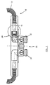
- a flow or return valve 30 for a heater is shown with a flow and return connection 32, 34.
- the vertically angled housing of a connector 20 is visible in the partial opening.
- the connector 10 is part of the plug connection as a movable component the lead, a smooth insertion section 14 and an adjoining this Corrugated tube 12 has.
- the insertion section 14 on the connector 20 to the Flow channel 32 can be connected.
- the detail surrounded by a circle in FIG. 1 is shown in more detail in FIGS. 2 to 3.
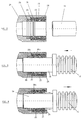
- FIGS. 2 to 4 The details of the connector according to the invention according to the illustrated embodiment are shown in FIGS. 2 to 4.
- Fig. 2 the connection is in the State shown as it can be seen in FIG. 1, namely before the introduction of the Insertion section 14 in the recording shown on the left.
- the insertion section 14 is a round smooth tube, for example a plastic tube.
- the image shown on the left consists of various individual components.
- an outer bushing 22 is inserted on the end face.
- the outer bush 22 is made preferably made of a plastic material; it bumps with its left end face in FIG. 2 to a paragraph of the housing 21 and is not in the opening area with one designated outer paragraph held in position in the housing 21.
- the outer bush 24 has a guide section 25 in the region of the left end face on which the insertion section 14 abuts in the assembled state.
- the end face of the outer bush 22 are two sealing rings in a recess in the housing 21 28 introduced, which is also in the assembled state on the outer circumference of the Insert section 14 and the space between the housing 21 and can seal this.
- the outer bush 22 detects an obliquely on the outside extending recess in which a spreading or clamping ring 26 is supported.
- the inner diameter of the expansion ring 26 is not inserted Condition slightly smaller than the diameter of the insertion section 14.
- the Expansion ring 26 has a radially extending bearing section 26b and an inner portion 26a extending obliquely to the left.
- the inner bush 24 is arranged, which is shown by means of a press fit in the right Area in the outer bush 22 is introduced axially.
- the inner bushing 24 has the release extension 23, which is called after left partial wedge is formed.
- the Plug in the state shown in Fig. 3.
- the insertion section 14 will when inserting the inner diameter of the inner bush 24 and later from Guide section 25 of the outer bush 22 enclosed after the expansion or Tension ring 26 has happened.
- the entry section 14 is further through the sealing rings 28 pushed through until it rests on a housing shoulder. So that's it Connection between the corrugated tube 12 and the flow connection 32 (Fig. 1) made.
- the inserted state of the plug connection is fixed, in particular It should be ensured that the interference fit of the inner bush 24 in the outer bush 22 is so strong that when inserting the insertion section 14 there is no axial displacement of the inner bush 24 to the left.
- FIG. 1 The state in which the plug connection according to the invention can be released again 3 is shown in FIG.
- loosening the connection for example when removing the heater or for maintenance work to be carried out, now comes the basic one Slidability of the inner bush 24 in a press fit in the outer bush 22 a special Role too.
- the aforementioned press fit should, as already indicated, so be carried out strictly that the inner bush 24 when inserting the insertion section 14 does not move axially, but under the action of a certain predetermined Force can be shifted to the left.
- the connection After pulling out the insertion section 14 from the receptacle, the connection can be returned to the state of FIG. 2. Although it is one completely pulling out the insertion section 14 is possible, that the inner bushing 22 during the entire extraction process in that shown in FIG. 4 Position remains. However, after pulling out the insertion section 14 also the release extension 23, which can bend slightly inward, without tension are so that the inner bushing 24 with the help of an expandable special tool, that engages them again to the right on the right end of the outer bushing 24 can be pushed back.
- the plug connection according to the invention is therefore not unusable after opening once, but can be reused.
Landscapes
- Engineering & Computer Science (AREA)
- Physics & Mathematics (AREA)
- Thermal Sciences (AREA)
- Chemical & Material Sciences (AREA)
- Combustion & Propulsion (AREA)
- Mechanical Engineering (AREA)
- General Engineering & Computer Science (AREA)
- Quick-Acting Or Multi-Walled Pipe Joints (AREA)
- Mechanical Coupling Of Light Guides (AREA)
- Surgical Instruments (AREA)
Applications Claiming Priority (2)
| Application Number | Priority Date | Filing Date | Title |
|---|---|---|---|
| DE19813514 | 1998-03-26 | ||
| DE1998113514 DE19813514A1 (de) | 1998-03-26 | 1998-03-26 | Steckverbindung |
Publications (1)
| Publication Number | Publication Date |
|---|---|
| EP0945689A2 true EP0945689A2 (fr) | 1999-09-29 |
Family
ID=7862515
Family Applications (1)
| Application Number | Title | Priority Date | Filing Date |
|---|---|---|---|
| EP98124222A Withdrawn EP0945689A2 (fr) | 1998-03-26 | 1998-12-17 | Connecteur à insertion |
Country Status (2)
| Country | Link |
|---|---|
| EP (1) | EP0945689A2 (fr) |
| DE (2) | DE19813514A1 (fr) |
Cited By (1)
| Publication number | Priority date | Publication date | Assignee | Title |
|---|---|---|---|---|
| EP1136765A3 (fr) * | 2000-03-23 | 2003-08-06 | KERMI GmbH | Dispositif de raccordement pour un radiateur |
Families Citing this family (1)
| Publication number | Priority date | Publication date | Assignee | Title |
|---|---|---|---|---|
| DE29806382U1 (de) * | 1998-04-07 | 1998-06-18 | Hans Berg GmbH & Co KG, 51580 Reichshof | Anschlußgarnitur für einen Plattenheizkörper |
-
1998
- 1998-03-26 DE DE1998113514 patent/DE19813514A1/de not_active Withdrawn
- 1998-12-17 EP EP98124222A patent/EP0945689A2/fr not_active Withdrawn
-
1999
- 1999-03-24 DE DE29905450U patent/DE29905450U1/de not_active Expired - Lifetime
Non-Patent Citations (1)
| Title |
|---|
| None |
Cited By (2)
| Publication number | Priority date | Publication date | Assignee | Title |
|---|---|---|---|---|
| EP1136765A3 (fr) * | 2000-03-23 | 2003-08-06 | KERMI GmbH | Dispositif de raccordement pour un radiateur |
| DE10014454B4 (de) * | 2000-03-23 | 2007-08-16 | Kermi Gmbh | Anschlusseinrichtung für einen Heizkörper |
Also Published As
| Publication number | Publication date |
|---|---|
| DE29905450U1 (de) | 1999-08-12 |
| DE19813514A1 (de) | 1999-09-30 |
Similar Documents
| Publication | Publication Date | Title |
|---|---|---|
| DE69633510T2 (de) | Steckrohrverbindung | |
| DE69212793T2 (de) | Verbindungsvorrichtung für Teile eines Fluid-Verteilungssystems, besagte Teile und System | |
| DE3686779T2 (de) | Schnellverbindung fuer rohre aus kunststoff oder metall. | |
| CH678884A5 (fr) | ||
| CH643931A5 (de) | Steckverbindung fuer druckleitungen. | |
| EP0610538A1 (fr) | Raccord rapide pour tuyaux, tubes flexibles et similaires | |
| DE7624660U1 (de) | Vorrichtung zum verbinden der enden zweier rohre | |
| DE69836553T2 (de) | Kuppelstück für rohre | |
| DE4214105A1 (de) | Steckverbinder fuer schlauch- oder rohrleitungen, insbesondere fuer kraftstoffleitungen von verbrennungsmotoren | |
| DE69508507T2 (de) | System zur axialen Festlegung eines langgestreckten Elements | |
| DE3923579A1 (de) | Anschlussarmatur fuer rohre, insbesondere fuer kunststoffrohre | |
| DE60020212T2 (de) | Rohrverbindungselement, insbesondere für kunststoffrohre | |
| DE60205765T2 (de) | Verbindungen | |
| DE69102241T2 (de) | Verbesserte Vorrichtung zum Verbinden eines Schlauchendes mit dem Ende eines starren Rohres. | |
| EP0945689A2 (fr) | Connecteur à insertion | |
| EP1740873B1 (fr) | Raccord pour tuyaux flexibles | |
| DE1808689B2 (de) | Vorrichtung zur federnden und dichtenden koaxialen Lagerung eines glatten Leitungsrohres in einem in einer Wand verankerten Futterrohr | |
| DE2910688A1 (de) | Rohrkupplung | |
| DE69006285T2 (de) | Verbindungsstück für Kunststoffrohre und Montageverfahren. | |
| DE2330552A1 (de) | Rohr- oder schlauchkupplung | |
| EP1445526A1 (fr) | Pièce de fixation pour un collier de serrage | |
| DE19957839C1 (de) | Verbindungsstück zur Verbindung eines Schlauchendes mit einem rohrförmigen Teil | |
| DE19634037C1 (de) | Schlauchtülle | |
| DE3731222C2 (fr) | ||
| DE19715293A1 (de) | Steckverbindung für Rohrleitungen |
Legal Events
| Date | Code | Title | Description |
|---|---|---|---|
| PUAI | Public reference made under article 153(3) epc to a published international application that has entered the european phase |
Free format text: ORIGINAL CODE: 0009012 |
|
| AK | Designated contracting states |
Kind code of ref document: A2 Designated state(s): AT BE CH CY DE DK ES FI FR GB GR IE IT LI LU MC NL PT SE |
|
| AX | Request for extension of the european patent |
Free format text: AL;LT;LV;MK;RO;SI |
|
| STAA | Information on the status of an ep patent application or granted ep patent |
Free format text: STATUS: THE APPLICATION HAS BEEN WITHDRAWN |
|
| 18W | Application withdrawn |
Withdrawal date: 20001115 |