EP0945919B1 - Méthode de fixation d'un contact électrique permanent à la traverse d'un rail de chemin de fer et le contact correspondant - Google Patents
Méthode de fixation d'un contact électrique permanent à la traverse d'un rail de chemin de fer et le contact correspondant Download PDFInfo
- Publication number
- EP0945919B1 EP0945919B1 EP98105145A EP98105145A EP0945919B1 EP 0945919 B1 EP0945919 B1 EP 0945919B1 EP 98105145 A EP98105145 A EP 98105145A EP 98105145 A EP98105145 A EP 98105145A EP 0945919 B1 EP0945919 B1 EP 0945919B1
- Authority
- EP
- European Patent Office
- Prior art keywords
- cover
- web
- electrical contact
- cylindrical sleeve
- cutout
- Prior art date
- Legal status (The legal status is an assumption and is not a legal conclusion. Google has not performed a legal analysis and makes no representation as to the accuracy of the status listed.)
- Expired - Lifetime
Links
- 238000000034 method Methods 0.000 title claims abstract description 28
- 239000000463 material Substances 0.000 claims abstract description 32
- 239000004020 conductor Substances 0.000 claims description 13
- ATJFFYVFTNAWJD-UHFFFAOYSA-N Tin Chemical compound [Sn] ATJFFYVFTNAWJD-UHFFFAOYSA-N 0.000 claims description 6
- 229910000881 Cu alloy Inorganic materials 0.000 claims description 4
- 238000006073 displacement reaction Methods 0.000 abstract description 4
- 238000004519 manufacturing process Methods 0.000 description 6
- 230000002093 peripheral effect Effects 0.000 description 3
- RYGMFSIKBFXOCR-UHFFFAOYSA-N Copper Chemical compound [Cu] RYGMFSIKBFXOCR-UHFFFAOYSA-N 0.000 description 2
- 229910000831 Steel Inorganic materials 0.000 description 2
- 229910052802 copper Inorganic materials 0.000 description 2
- 239000010949 copper Substances 0.000 description 2
- 238000009434 installation Methods 0.000 description 2
- 238000012545 processing Methods 0.000 description 2
- 238000000926 separation method Methods 0.000 description 2
- 239000010959 steel Substances 0.000 description 2
- 241000209035 Ilex Species 0.000 description 1
- QCWXUUIWCKQGHC-UHFFFAOYSA-N Zirconium Chemical compound [Zr] QCWXUUIWCKQGHC-UHFFFAOYSA-N 0.000 description 1
- 229910052790 beryllium Inorganic materials 0.000 description 1
- ATBAMAFKBVZNFJ-UHFFFAOYSA-N beryllium atom Chemical compound [Be] ATBAMAFKBVZNFJ-UHFFFAOYSA-N 0.000 description 1
- 230000003750 conditioning effect Effects 0.000 description 1
- 238000013461 design Methods 0.000 description 1
- 230000006866 deterioration Effects 0.000 description 1
- 238000005553 drilling Methods 0.000 description 1
- 238000005868 electrolysis reaction Methods 0.000 description 1
- 238000003780 insertion Methods 0.000 description 1
- 230000037431 insertion Effects 0.000 description 1
- 239000000314 lubricant Substances 0.000 description 1
- 229910052751 metal Inorganic materials 0.000 description 1
- 239000002184 metal Substances 0.000 description 1
- 150000002739 metals Chemical class 0.000 description 1
- PEUPIGGLJVUNEU-UHFFFAOYSA-N nickel silicon Chemical compound [Si].[Ni] PEUPIGGLJVUNEU-UHFFFAOYSA-N 0.000 description 1
- 230000003647 oxidation Effects 0.000 description 1
- 238000007254 oxidation reaction Methods 0.000 description 1
- 230000000750 progressive effect Effects 0.000 description 1
- 229910052712 strontium Inorganic materials 0.000 description 1
- CIOAGBVUUVVLOB-UHFFFAOYSA-N strontium atom Chemical compound [Sr] CIOAGBVUUVVLOB-UHFFFAOYSA-N 0.000 description 1
- 229910052726 zirconium Inorganic materials 0.000 description 1
Images


Classifications
-
- H—ELECTRICITY
- H01—ELECTRIC ELEMENTS
- H01R—ELECTRICALLY-CONDUCTIVE CONNECTIONS; STRUCTURAL ASSOCIATIONS OF A PLURALITY OF MUTUALLY-INSULATED ELECTRICAL CONNECTING ELEMENTS; COUPLING DEVICES; CURRENT COLLECTORS
- H01R4/00—Electrically-conductive connections between two or more conductive members in direct contact, i.e. touching one another; Means for effecting or maintaining such contact; Electrically-conductive connections having two or more spaced connecting locations for conductors and using contact members penetrating insulation
- H01R4/28—Clamped connections, spring connections
- H01R4/50—Clamped connections, spring connections utilising a cam, wedge, cone or ball also combined with a screw
- H01R4/5016—Clamped connections, spring connections utilising a cam, wedge, cone or ball also combined with a screw using a cone
-
- H—ELECTRICITY
- H01—ELECTRIC ELEMENTS
- H01R—ELECTRICALLY-CONDUCTIVE CONNECTIONS; STRUCTURAL ASSOCIATIONS OF A PLURALITY OF MUTUALLY-INSULATED ELECTRICAL CONNECTING ELEMENTS; COUPLING DEVICES; CURRENT COLLECTORS
- H01R4/00—Electrically-conductive connections between two or more conductive members in direct contact, i.e. touching one another; Means for effecting or maintaining such contact; Electrically-conductive connections having two or more spaced connecting locations for conductors and using contact members penetrating insulation
- H01R4/58—Electrically-conductive connections between two or more conductive members in direct contact, i.e. touching one another; Means for effecting or maintaining such contact; Electrically-conductive connections having two or more spaced connecting locations for conductors and using contact members penetrating insulation characterised by the form or material of the contacting members
- H01R4/64—Connections between or with conductive parts having primarily a non-electric function, e.g. frame, casing, rail
-
- H—ELECTRICITY
- H01—ELECTRIC ELEMENTS
- H01R—ELECTRICALLY-CONDUCTIVE CONNECTIONS; STRUCTURAL ASSOCIATIONS OF A PLURALITY OF MUTUALLY-INSULATED ELECTRICAL CONNECTING ELEMENTS; COUPLING DEVICES; CURRENT COLLECTORS
- H01R4/00—Electrically-conductive connections between two or more conductive members in direct contact, i.e. touching one another; Means for effecting or maintaining such contact; Electrically-conductive connections having two or more spaced connecting locations for conductors and using contact members penetrating insulation
- H01R4/28—Clamped connections, spring connections
- H01R4/30—Clamped connections, spring connections utilising a screw or nut clamping member
Definitions
- the above invention relates to a method for producing a permanent electrical contact on the web of a railway rail, providing a through hole in the web of the rail and inserting a sleeve of electrically conductive material having a through hole.
- the invention further relates to a permanent, electrical contact, which is produced by the method and consists of a, having a through hole sleeve having a collar at one end and consists of electrically conductive material.
- the material displaced in a known manner does not form a surface which would be suitable for the production of an electrical contact, since the material displaced during the drawing process is deposited irregularly on the web of the rail.
- the object of the present invention is to obviate the aforementioned disadvantages of the prior art and to propose a method and a device which makes it possible to produce a permanent, electrical contact which can be used for electrical connections on both sides of the web of a rail body and at the same time excellent and constant, electrical and mechanical features.
- the inner circumferential wall of the lid is conical.
- the displaced from the cylindrical sleeve material is brought to the undercut peripheral wall of the conical recess for conditioning.
- the free end of the sleeve in the circumferential direction has a frustoconical groove formed.
- the cover In order to allow the calibrated drawing tool of the sleeve to emerge from the cover surrounding the sleeve end after the drawing operation has been carried out, the cover has an opening which is dimensioned larger than the maximum diameter of the drawing tool.
- the inlet opening in the recess of the lid dimensions that match the diameter of the bore into which the cylindrical sleeve is inserted, match.
- the inner recess of the lid on an undercut inclined by 10 ° relative to the longitudinal axis of the lid peripheral wall.
- the material of the cylindrical sleeve displaced during the drawing process which exits the bore of the sleeve during the drawing process, is not subjected to any pronounced deformations during the plastic deformation, and it is possible to fill the recess in the interior of the cover with the displaced material , and to bring this material into close contact with the undercut wall.
- this lid is made of a copper alloy, which has very good electrical conductivity and increased mechanical resistance.
- the cover and the cylindrical sleeve made of materials that have the same coefficient of thermal expansion.
- the cylindrical sleeve and the lid is coated with a tin layer.
- the cylindrical sleeve communicating with web of the rail and the terminating cap receives a screw, and this screw takes the terminal shoes of the electrical conductors on the flange surface of the cylindrical sleeve and on the flat surface of the attached lid on.
- a chamber is formed by the inner recess of the end cap, which can accommodate different amounts of displaced during the drawing process and emerging from the through hole of the cylindrical sleeve material.
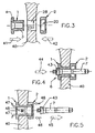
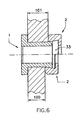
- FIGS. 1 and 2 show a cylindrical sleeve and a cover attached to the free end of the sleeve.
- the cylindrical sleeve 1 has a cylindrical piece 3.
- the cylindrical sleeve 1 has a molded-on flange 4, which is designed as a contact flange and as an electrical contact.
- the cylindrical sleeve 1 is penetrated in the axial direction by a bore 102.
- the flange 4 On the outside, the flange 4 has a slightly convex surface 5.
- the flange 4 of the cylindrical sleeve 1 has a recess 6 which is adapted to receive the head of a drawing tool 7, with which the drawing operation of the cylindrical sleeve 3 of the component 1 takes place ( Figure 4).
- the free end of the cylindrical sleeve 3 also has at its front end a recess 10 which is adapted to receive the resulting during the drawing process Materialwall.
- the recess 10 has advantageously a truncated cone-like shape.
- the end cover 2 has on one side a flat surface 15 to provide an electrical contact surface.
- the bore 16 of the lid 2 has a diameter which is greater than the maximum cross section of the pulling head 7.
- the lid 2 also has an inner recess 20.
- the inner recess 20 conical and is bounded by a circumferential wall which forms an undercut.
- the inlet 21 of the recess 20 has a diameter 22 which is slightly larger than the diameter 25 of the cylindrical sleeve 3.
- the dimensions 22 of the inlet 21 of the inner recess 20 are chosen in accordance with the diameter 27 of the bore 28.
- the cylindrical sleeve 3 of the part 1 is used for the production of a permanent electrical contact on the web of a rail track.
- the inner recess 20 has a peripheral wall 30 which is inclined at approximately 10 ° relative to the axis 31 of the cover 2.
- the inner recess 20 has a depth 32 which is sufficient to define a chamber 33 inside the lid 2.
- the chamber is designed such that it can accommodate the largest possible amount of material that is displaced during the drawing process of the cylindrical sleeve 1.
- the cylindrical sleeve 1 is made of electrically conductive material, e.g. made of electrolytic copper.
- the lid 2 is made of an electrically conductive material having mechanical features sufficient to withstand the compressive forces encountered during the process to record the drawing process.
- the covers 2 are advantageously made of a copper alloy, e.g. Copper alloyed with beryllium, strontium, zirconium, nickel-silicon.
- cylindrical sleeve 1 and the cover 2 is made using a material having the same coefficient of thermal expansion.
- cylindrical sleeve 1 and the cover 2 are coated with a tin layer.
- tin layer avoids possible electrolysis between the copper material of the cylindrical sleeve and the attached cover and the rail body made of steel. This is due to the fact that tin is electrolytic in one Intermediate position between these two metals.
- the first step to be carried out is that the web 40 of the rail body is provided with a through bore. It is provided that the diameter of the drilling tool is slightly larger than the dimensions 25 of the circumferential casing 26 of the cylindrical sleeve 3.
- the bore 28 of the web 40 of the rail body can accommodate the cylindrical sleeve 3 free.
- the possibility opens, in the bore 28 to use a measuring and control caliber.
- This caliber has sige design and is supplied together with the mounting device, not shown.
- the calibrated head 7 of the pulling tool is inserted into the through hole 102 of the cylindrical sleeve 1 from the side of the abutment flange 4.
- the frustoconically formed part 43 of the calibrated pulling head 7 (in the direction of the arrow 44) is inserted into the inner recess 6 of the cylindrical sleeve 1.
- a lubricant was introduced into the recess 6 prior to introduction of the drawing tool.
- An extension of the calibrated head of the drawing tool 7 occurs after insertion into the through hole 102 of the sleeve 1 on the side opposite the bottle 4 side of the sleeve from this.
- the inner recess 20 of the lid 2 is directed to the web 40 of the rail body (arrow 42).
- the lid 2 is centered relative to the bore 28 in the web 40 of the rail body and thus relative to the shaft 3 of the cylindrical sleeve. 1
- the lid 2 is held in abutment with the web 40 of the rail body.
- the conical portion 43 of the pulling head 7 brings during the expansion pulling operation of the sleeve 1 derenn outer jacket 26 in frictional connection with the wall of the bore 28, whereby an excellent, permanent, electrical contact created becomes.
- the force caused by the head 43 of the drawing tool deforms the initially spherical surface 5 of the flange 4 of the cylindrical sleeve 1 in a flat surface (arrow 47).
- the displaced material of the cylindrical sleeve 3 accumulates like a wall during the drawing process and is received in the chamber 33, which is formed by the recess 20 of the cover 2 (arrow 48).
- the accumulated material flows to the wall 30 of the cover 2 and thus generates the desired electrical contact between the sleeve 1 of the cover 2 and simultaneously forms a positive and positive connection between the cover 2 and the end of the sleeve 1.
- both lugs are mounted using a single screw 55 and firmly clamped.
Landscapes
- Insulating Bodies (AREA)
- Insulators (AREA)
- Machines For Laying And Maintaining Railways (AREA)
- Train Traffic Observation, Control, And Security (AREA)
- Connections Effected By Soldering, Adhesion, Or Permanent Deformation (AREA)
- Near-Field Transmission Systems (AREA)
Claims (13)
- Procédé pour établir un contact électrique permanent au niveau de l'âme (40) d'un corps de rail (52) en réalisant une opération de serrage, un orifice traversant (28) étant aménagé dans l'âme (40) du corps de rail (52) et une douille cylindrique (3) étant insérée dans cet orifice traversant (28), laquelle présente un orifice traversant (102) et présente à une extrémité une collerette d'appui (4) qui est amenée en appui avec un côté de l'âme (40) du corps de rail (52), caractérisé en ce qu'un couvercle (2) est monté sur l'extrémité libre de la douille cylindrique (3) qui traverse l'âme du rail, lequel entoure avec un creux intérieur (20) l'extrémité de la douille (3) et que l'orifice traversant (102) est soumis à une opération de serrage et le matériau chassé est introduit dans le creux intérieur (20) du couvercle (2) et amené en appui par adhérence et par engagement géométrique contve les parois (30) du creux (20).
- Contact électrique permanent au niveau de l'âme (40) d'un corps de rail (52), le contact étant soumis à une opération de serrage et l'âme (40) du corps de rail (52) présentant un orifice traversant (28) destiné à recevoir une douille cylindrique (3) qui est munie d'un orifice traversant (102) et comporte à une extrémité une collerette d'appui (4) qui est appuyée d'un côté de l'âme (40) du corps de rail (52), caractérisé en ce qu'un couvercle (2) enveloppant l'extrémité libre de la douille cylindrique (3) est disposé sur le côté de l'âme du rail (40) opposé à la collerette d'appui (4), lequel présente sur son côté extérieur une surface de contact plane (15), que le couvercle (2), sur son côté dirigé vers l'âme (40), accueille un creux intérieur (20) qui entoure l'extrémité libre de la douille cylindrique (3) et le matériau chassé pendant l'opération de serrage de l'orifice traversant (102) est introduit dans le creux intérieur (20) du couvercle (2) et celui-ci est appuyé par adhérence et par engagement géométrique contre les parois du creux (20).
- Contact électrique selon la revendication 2, caractérisé en ce que le creux (20) du couvercle (2) présente une forme conique.
- Contact électrique selon la revendication 3, caractérisé en ce que le matériau chassé hors de l'orifice traversant (102) de la douille (3) vient en appui contre la paroi (30) du creux (20) qui forme une contre-dépouille.
- Contact électrique selon la revendication 2, caractérisé en ce que l'extrémité libre de la douille cylindrique (3) présente du côté de la tête un creux tronconique (10).
- Contact électrique selon la revendication 2, caractérisé en ce que le couvercle (2) présente un orifice (16) qui possède un diamètre supérieur à celui de la tête de l'outil de serrage (7).
- Contact électrique selon la revendication 2, caractérisé en ce que l'entrée (21) du creux (20) du couvercle (2) présente une cote (22) qui coïncide au diamètre (27) de l'orifice (28) dans l'âme (40).
- Contact électrique selon la revendication 3, caractérisé en ce que le creux intérieur (20) du couvercle (2) présente une paroi (30) qui délimite une contre-dépouille et la paroi (30) est disposée selon un angle de 10° par rapport à l'axe (31) du couvercle (2).
- Contact électrique selon la revendication 2, caractérisé en ce que le couvercle (2) se compose d'un alliage de cuivre à haute conductivité électrique.
- Contact électrique selon la revendication 2, caractérisé en ce que le couvercle (2) se compose d'un alliage de cuivre à résistance mécanique accrue.
- Contact électrique selon la revendication 2, caractérisé en ce que le couvercle (2) et la douille cylindrique (1) se composent de matériaux qui présentent les mêmes coefficients de dilatation thermique.
- Contact électrique selon la revendication 2, caractérisé en ce que la douille cylindrique (1) et le couvercle (2) sont revêtus d'une couche d'étain.
- Contact électrique selon la revendication 2, caractérisé en ce que le douille cylindrique (1) qui est reliée avec le couvercle (2) et l'âme (40) du corps de rail (52) reçoit une vis (55) et la vis (55) reçoit le conducteur (50) muni d'une cosse de raccordement (51) et cette cosse de raccordement est comprimée contre la surface (5) de la collerette (4) de la douille (1) et contre la surface plane (15) du couvercle (2) en utilisant des assemblages vissés (55).
Priority Applications (4)
| Application Number | Priority Date | Filing Date | Title |
|---|---|---|---|
| EP98105145A EP0945919B1 (fr) | 1998-03-22 | 1998-03-22 | Méthode de fixation d'un contact électrique permanent à la traverse d'un rail de chemin de fer et le contact correspondant |
| AT98105145T ATE315838T1 (de) | 1998-03-22 | 1998-03-22 | Verfahren zur herstellung eines elektrischen dauerkontaktes am steg einer eisenbahnschiene und mit dem verfahren hergestellter elektrischer dauerkontakt |
| ES98105145T ES2256901T3 (es) | 1998-03-22 | 1998-03-22 | Procedimiento para establecer un contacto electrico permanente en el alma de un rail ferroviario y contacto electrico permanente obtenido con dicho procedimiento. |
| DE59813339T DE59813339D1 (de) | 1998-03-22 | 1998-03-22 | Verfahren zur Herstellung eines elektrischen Dauerkontaktes am Steg einer Eisenbahnschiene und mit dem Verfahren hergestellter elektrischer Dauerkontakt |
Applications Claiming Priority (1)
| Application Number | Priority Date | Filing Date | Title |
|---|---|---|---|
| EP98105145A EP0945919B1 (fr) | 1998-03-22 | 1998-03-22 | Méthode de fixation d'un contact électrique permanent à la traverse d'un rail de chemin de fer et le contact correspondant |
Publications (2)
| Publication Number | Publication Date |
|---|---|
| EP0945919A1 EP0945919A1 (fr) | 1999-09-29 |
| EP0945919B1 true EP0945919B1 (fr) | 2006-01-11 |
Family
ID=8231632
Family Applications (1)
| Application Number | Title | Priority Date | Filing Date |
|---|---|---|---|
| EP98105145A Expired - Lifetime EP0945919B1 (fr) | 1998-03-22 | 1998-03-22 | Méthode de fixation d'un contact électrique permanent à la traverse d'un rail de chemin de fer et le contact correspondant |
Country Status (4)
| Country | Link |
|---|---|
| EP (1) | EP0945919B1 (fr) |
| AT (1) | ATE315838T1 (fr) |
| DE (1) | DE59813339D1 (fr) |
| ES (1) | ES2256901T3 (fr) |
Cited By (15)
| Publication number | Priority date | Publication date | Assignee | Title |
|---|---|---|---|---|
| US7926319B2 (en) | 2005-12-28 | 2011-04-19 | Fatigue Technology, Inc. | Mandrel assembly and method of using the same |
| US7926318B2 (en) | 2006-04-27 | 2011-04-19 | Fatigue Technology, Inc. | Alignment device and methods of using the same |
| US7946628B2 (en) | 2003-07-31 | 2011-05-24 | Fatigue Technology, Inc. | Tubular metal fitting expandable in a wall opening and method of installation |
| US7958766B2 (en) | 2006-06-29 | 2011-06-14 | Fatigue Technology, Inc. | Self-aligning tools and a mandrel with retention sleeve |
| US8069699B2 (en) | 2006-08-28 | 2011-12-06 | Fatigue Technology, Inc. | Installation/processing systems and methods of using the same |
| US8128308B2 (en) | 2000-06-26 | 2012-03-06 | Fatigue Technology Inc. | Double flanged bushings and installation methods |
| US8312606B2 (en) | 2007-10-16 | 2012-11-20 | Fatigue Technology, Inc. | Expandable fastener assembly with deformed collar |
| US8506222B2 (en) | 2008-07-18 | 2013-08-13 | Fatigue Technology, Inc. | Nut plate assembly and methods of using the same |
| US8568034B2 (en) | 2006-01-11 | 2013-10-29 | Fatigue Technology, Inc. | Bushing kits, bearings, and methods of installation |
| US8636455B2 (en) | 2009-04-10 | 2014-01-28 | Fatigue Technoloy, Inc. | Installable assembly having an expandable outer member and a fastener with a mandrel |
| US8647035B2 (en) | 2009-12-16 | 2014-02-11 | Fatigue Technology, Inc. | Modular nut plate assemblies and methods of using the same |
| US8763229B2 (en) | 2011-06-03 | 2014-07-01 | Fatigue Technology, Inc. | Expandable crack inhibitor method |
| US8938886B2 (en) | 2012-01-30 | 2015-01-27 | Fatigue Technology, Inc. | Smart installation/processing systems, components, and methods of operating the same |
| US9114449B2 (en) | 2011-06-15 | 2015-08-25 | Fatigue Technology, Inc. | Modular nut plates with closed nut assemblies |
| US10010983B2 (en) | 2008-03-07 | 2018-07-03 | Fatigue Technology, Inc. | Expandable member with wave inhibitor and methods of using the same |
Families Citing this family (10)
| Publication number | Priority date | Publication date | Assignee | Title |
|---|---|---|---|---|
| SE527876C2 (sv) * | 2004-11-26 | 2006-07-04 | Safetrack Infrasystems Sisab A | Metod och anordning för anslutning av en elektrisk ledare till en metallskena samt verktyg för fastsättning av en bussning i ett hål i en metallskena |
| US20070110541A1 (en) * | 2005-10-28 | 2007-05-17 | Fatigue Technology, Inc. | Radially displaceable bushing for retaining a member relative to a structural workpiece |
| WO2007127399A2 (fr) | 2006-04-27 | 2007-11-08 | Fatigue Technology, Inc. | Caractéristiques géométriques de décharge pour vague dans des éléments structuraux dilatables radialement à l'intérieur de pièces |
| FR2922370B1 (fr) * | 2007-10-15 | 2009-11-20 | Eldre | Borne de connexion electrique. |
| WO2011072752A1 (fr) * | 2009-12-18 | 2011-06-23 | Cembre Ltd | Procédé et coffret pour l'application d'un contact électrique permanent dans l'âme d'un rail et similaire |
| IT1398327B1 (it) * | 2010-02-26 | 2013-02-22 | Cembre Spa | Dispositivo di tiro per tirare un punzone attraverso una bussola di contatto |
| WO2013086333A1 (fr) | 2011-12-07 | 2013-06-13 | Eldre Corporation | Appareil de traversée amovible de barre omnibus |
| ITMI20120406A1 (it) | 2012-03-15 | 2013-09-16 | Cembre Spa | Contatto elettrico permanente applicabile sull'anima di rotaie e simili |
| CN109131438A (zh) * | 2018-08-27 | 2019-01-04 | 深圳市森博尔电力设备科技有限公司 | 一种铁路轨道回流系统 |
| CN109722950B (zh) * | 2019-01-14 | 2024-06-21 | 上海国爱电气有限公司 | 一种杂散电流均回流电缆专用35°角接线端子 |
Family Cites Families (2)
| Publication number | Priority date | Publication date | Assignee | Title |
|---|---|---|---|---|
| IT1215911B (it) * | 1988-02-18 | 1990-02-22 | Cembre Srl | Contatto elettrico permanente applicabile sull'anima di rotaie esimili. |
| DE29712206U1 (de) * | 1997-07-11 | 1997-08-28 | Kabelkonfektionstechnik KKT GmbH, 96515 Sonneberg | Vorrichtung zum Anschluß einer elektrischen Leitung an einem Eisenbahnschienensteg o.dgl. |
-
1998
- 1998-03-22 EP EP98105145A patent/EP0945919B1/fr not_active Expired - Lifetime
- 1998-03-22 AT AT98105145T patent/ATE315838T1/de active
- 1998-03-22 ES ES98105145T patent/ES2256901T3/es not_active Expired - Lifetime
- 1998-03-22 DE DE59813339T patent/DE59813339D1/de not_active Expired - Lifetime
Cited By (23)
| Publication number | Priority date | Publication date | Assignee | Title |
|---|---|---|---|---|
| US8128308B2 (en) | 2000-06-26 | 2012-03-06 | Fatigue Technology Inc. | Double flanged bushings and installation methods |
| US7946628B2 (en) | 2003-07-31 | 2011-05-24 | Fatigue Technology, Inc. | Tubular metal fitting expandable in a wall opening and method of installation |
| US7926319B2 (en) | 2005-12-28 | 2011-04-19 | Fatigue Technology, Inc. | Mandrel assembly and method of using the same |
| US8353193B2 (en) | 2005-12-28 | 2013-01-15 | Fatigue Technology, Inc. | Mandrel assembly and method of using the same |
| US8568034B2 (en) | 2006-01-11 | 2013-10-29 | Fatigue Technology, Inc. | Bushing kits, bearings, and methods of installation |
| US8387436B2 (en) | 2006-04-27 | 2013-03-05 | Fatigue Technology, Inc. | Alignment device and methods of using the same |
| US7926318B2 (en) | 2006-04-27 | 2011-04-19 | Fatigue Technology, Inc. | Alignment device and methods of using the same |
| US8191395B2 (en) | 2006-04-27 | 2012-06-05 | Fatigue Technology, Inc. | Alignment device and methods of using the same |
| US7958766B2 (en) | 2006-06-29 | 2011-06-14 | Fatigue Technology, Inc. | Self-aligning tools and a mandrel with retention sleeve |
| US8061178B2 (en) | 2006-06-29 | 2011-11-22 | Fatigue Technology, Inc. | Self-aligning tools and seating assemblies |
| US8117885B2 (en) | 2006-06-29 | 2012-02-21 | Fatigue Technology, Inc. | Mandrel with retention sleeve and methods of using the same |
| US8069699B2 (en) | 2006-08-28 | 2011-12-06 | Fatigue Technology, Inc. | Installation/processing systems and methods of using the same |
| US8402806B2 (en) | 2006-08-28 | 2013-03-26 | Fatigue Technology, Inc. | Installation/processing systems and methods of using the same |
| US8312606B2 (en) | 2007-10-16 | 2012-11-20 | Fatigue Technology, Inc. | Expandable fastener assembly with deformed collar |
| US10010983B2 (en) | 2008-03-07 | 2018-07-03 | Fatigue Technology, Inc. | Expandable member with wave inhibitor and methods of using the same |
| US8506222B2 (en) | 2008-07-18 | 2013-08-13 | Fatigue Technology, Inc. | Nut plate assembly and methods of using the same |
| US8636455B2 (en) | 2009-04-10 | 2014-01-28 | Fatigue Technoloy, Inc. | Installable assembly having an expandable outer member and a fastener with a mandrel |
| US8647035B2 (en) | 2009-12-16 | 2014-02-11 | Fatigue Technology, Inc. | Modular nut plate assemblies and methods of using the same |
| US8763229B2 (en) | 2011-06-03 | 2014-07-01 | Fatigue Technology, Inc. | Expandable crack inhibitor method |
| US9114449B2 (en) | 2011-06-15 | 2015-08-25 | Fatigue Technology, Inc. | Modular nut plates with closed nut assemblies |
| US8938886B2 (en) | 2012-01-30 | 2015-01-27 | Fatigue Technology, Inc. | Smart installation/processing systems, components, and methods of operating the same |
| US10130985B2 (en) | 2012-01-30 | 2018-11-20 | Fatigue Technology, Inc. | Smart installation/processing systems, components, and methods of operating the same |
| US10843250B2 (en) | 2012-01-30 | 2020-11-24 | Fatigue Technology, Inc. | Smart installation/processing systems, components, and methods of operating the same |
Also Published As
| Publication number | Publication date |
|---|---|
| ES2256901T3 (es) | 2006-07-16 |
| DE59813339D1 (de) | 2006-04-06 |
| EP0945919A1 (fr) | 1999-09-29 |
| ATE315838T1 (de) | 2006-02-15 |
Similar Documents
| Publication | Publication Date | Title |
|---|---|---|
| EP0945919B1 (fr) | Méthode de fixation d'un contact électrique permanent à la traverse d'un rail de chemin de fer et le contact correspondant | |
| DE102016105768B3 (de) | Elektrischer Leiter mit einer Reibschweißhülse | |
| DE69406065T2 (de) | Verfahren zum Anschliessen eines elektrischen Kabels an einem Anschlusselement und das Anschlusselement selbst | |
| EP2301115B1 (fr) | Dispositif de connexion électrique | |
| EP3189561B1 (fr) | Contact a sertir | |
| EP1524731B1 (fr) | Boîtier de connecteur avec étanchéité améliorée pour câble | |
| DE10259803B3 (de) | Elektrische Anschlussverbindung, insbesondere für den Anschluss eines Außenleiters eines Koaxialkabels | |
| DE102020106415B4 (de) | REIBSCHWEIßVERBINDER UND VERFAHREN ZU DESSEN HERSTELLUNG | |
| DE102017123864B3 (de) | Elektrische Leitungsanordnung mit Direktkontaktierung und Verfahren zu deren Herstellung | |
| DE102013013368B4 (de) | Verfahren zur Herstellung einer elektrischen Verbindung sowie elektrische Verbindung | |
| DE102022003696A1 (de) | Verfahren zur herstellung eines montagezustands einer baugruppe und baugruppe | |
| EP0655805A1 (fr) | Fiche pour câble | |
| DE19609425A1 (de) | Einpreßstift | |
| EP2940803B1 (fr) | Connection électrique pour des câbles de courant | |
| DE19704824A1 (de) | Verfahren und Vorrichtung zum Verbinden von Rohren aus einem plastisch verformbaren Werkstoff | |
| DE102019116127B4 (de) | Schleifkontakt und Verfahren zur Herstellung eines Schleifkontakts | |
| EP1263089B1 (fr) | Arrangement de connexion pour câbles | |
| DE102012221466B4 (de) | Bauteilverbund zwischen zwei der Stromführung dienenden Bauteilen und Verfahren zur Herstellung eines Bauteileverbunds | |
| DE102018109306B4 (de) | Verfahren zur Herstellung einer elektrischen Heizvorrichtung | |
| EP4002592B1 (fr) | Connecteur pour une conduite électrique et raccordement de conduite | |
| EP3736920B1 (fr) | Borne de contact et son procédé de fabrication | |
| EP0203253A2 (fr) | Connexion de connecteurs électrique non déconnectable capsulée | |
| DE19940361A1 (de) | Kabelgarnitur in Form eines Steckendverschlusses und/oder Kabel-Verbindungsmuffe | |
| DE3531038A1 (de) | Stecker fuer ein koaxialkabel | |
| DE102013022354B3 (de) | Verfahren zur Herstellung einer elektrischen Verbindung sowie elektrische Verbindung |
Legal Events
| Date | Code | Title | Description |
|---|---|---|---|
| PUAI | Public reference made under article 153(3) epc to a published international application that has entered the european phase |
Free format text: ORIGINAL CODE: 0009012 |
|
| AK | Designated contracting states |
Kind code of ref document: A1 Designated state(s): AT BE CH DE DK ES FR GB IT LI NL PT SE |
|
| AX | Request for extension of the european patent |
Free format text: AL;LT;LV;MK;RO;SI |
|
| RTI1 | Title (correction) |
Free format text: METHOD FOR ESTABLISHING A PERMANENT ELECTRIC CONTACT TO THE WEB OF RAILS AND THE CORRESPONDING CONTACT |
|
| 17P | Request for examination filed |
Effective date: 19991115 |
|
| AKX | Designation fees paid |
Free format text: AT BE CH DE DK ES FR GB IT LI NL PT SE |
|
| GRAP | Despatch of communication of intention to grant a patent |
Free format text: ORIGINAL CODE: EPIDOSNIGR1 |
|
| GRAS | Grant fee paid |
Free format text: ORIGINAL CODE: EPIDOSNIGR3 |
|
| GRAA | (expected) grant |
Free format text: ORIGINAL CODE: 0009210 |
|
| AK | Designated contracting states |
Kind code of ref document: B1 Designated state(s): AT BE CH DE DK ES FR GB IT LI NL PT SE |
|
| REG | Reference to a national code |
Ref country code: CH Ref legal event code: EP |
|
| REF | Corresponds to: |
Ref document number: 59813339 Country of ref document: DE Date of ref document: 20060406 Kind code of ref document: P |
|
| PG25 | Lapsed in a contracting state [announced via postgrant information from national office to epo] |
Ref country code: DK Free format text: LAPSE BECAUSE OF FAILURE TO SUBMIT A TRANSLATION OF THE DESCRIPTION OR TO PAY THE FEE WITHIN THE PRESCRIBED TIME-LIMIT Effective date: 20060411 |
|
| REG | Reference to a national code |
Ref country code: CH Ref legal event code: NV Representative=s name: FREI PATENTANWALTSBUERO |
|
| REG | Reference to a national code |
Ref country code: SE Ref legal event code: TRGR |
|
| GBT | Gb: translation of ep patent filed (gb section 77(6)(a)/1977) |
Effective date: 20060420 |
|
| PG25 | Lapsed in a contracting state [announced via postgrant information from national office to epo] |
Ref country code: PT Free format text: LAPSE BECAUSE OF FAILURE TO SUBMIT A TRANSLATION OF THE DESCRIPTION OR TO PAY THE FEE WITHIN THE PRESCRIBED TIME-LIMIT Effective date: 20060612 |
|
| REG | Reference to a national code |
Ref country code: ES Ref legal event code: FG2A Ref document number: 2256901 Country of ref document: ES Kind code of ref document: T3 |
|
| ET | Fr: translation filed | ||
| PLBE | No opposition filed within time limit |
Free format text: ORIGINAL CODE: 0009261 |
|
| STAA | Information on the status of an ep patent application or granted ep patent |
Free format text: STATUS: NO OPPOSITION FILED WITHIN TIME LIMIT |
|
| 26N | No opposition filed |
Effective date: 20061012 |
|
| REG | Reference to a national code |
Ref country code: FR Ref legal event code: PLFP Year of fee payment: 19 |
|
| REG | Reference to a national code |
Ref country code: FR Ref legal event code: PLFP Year of fee payment: 20 |
|
| PGFP | Annual fee paid to national office [announced via postgrant information from national office to epo] |
Ref country code: SE Payment date: 20170323 Year of fee payment: 20 Ref country code: FR Payment date: 20170323 Year of fee payment: 20 Ref country code: CH Payment date: 20170323 Year of fee payment: 20 Ref country code: NL Payment date: 20170323 Year of fee payment: 20 |
|
| PGFP | Annual fee paid to national office [announced via postgrant information from national office to epo] |
Ref country code: BE Payment date: 20170220 Year of fee payment: 20 Ref country code: AT Payment date: 20170330 Year of fee payment: 20 Ref country code: GB Payment date: 20170323 Year of fee payment: 20 |
|
| PGFP | Annual fee paid to national office [announced via postgrant information from national office to epo] |
Ref country code: IT Payment date: 20170130 Year of fee payment: 20 |
|
| PGFP | Annual fee paid to national office [announced via postgrant information from national office to epo] |
Ref country code: DE Payment date: 20170403 Year of fee payment: 20 |
|
| PGFP | Annual fee paid to national office [announced via postgrant information from national office to epo] |
Ref country code: ES Payment date: 20170328 Year of fee payment: 20 |
|
| REG | Reference to a national code |
Ref country code: NL Ref legal event code: MK Effective date: 20180321 |
|
| REG | Reference to a national code |
Ref country code: DE Ref legal event code: R071 Ref document number: 59813339 Country of ref document: DE |
|
| REG | Reference to a national code |
Ref country code: CH Ref legal event code: PL |
|
| REG | Reference to a national code |
Ref country code: BE Ref legal event code: MK Effective date: 20180322 |
|
| REG | Reference to a national code |
Ref country code: GB Ref legal event code: PE20 Expiry date: 20180321 |
|
| PG25 | Lapsed in a contracting state [announced via postgrant information from national office to epo] |
Ref country code: GB Free format text: LAPSE BECAUSE OF EXPIRATION OF PROTECTION Effective date: 20180321 |
|
| REG | Reference to a national code |
Ref country code: SE Ref legal event code: EUG |
|
| REG | Reference to a national code |
Ref country code: AT Ref legal event code: MK07 Ref document number: 315838 Country of ref document: AT Kind code of ref document: T Effective date: 20180322 |
|
| REG | Reference to a national code |
Ref country code: ES Ref legal event code: FD2A Effective date: 20200721 |
|
| PG25 | Lapsed in a contracting state [announced via postgrant information from national office to epo] |
Ref country code: ES Free format text: LAPSE BECAUSE OF EXPIRATION OF PROTECTION Effective date: 20180323 |