EP0945946A2 - Dispositif pour supporter des caniveaux de câbles en matière synthétique à proximité de lignes de chemin de fer électrifiées - Google Patents
Dispositif pour supporter des caniveaux de câbles en matière synthétique à proximité de lignes de chemin de fer électrifiées Download PDFInfo
- Publication number
- EP0945946A2 EP0945946A2 EP99250038A EP99250038A EP0945946A2 EP 0945946 A2 EP0945946 A2 EP 0945946A2 EP 99250038 A EP99250038 A EP 99250038A EP 99250038 A EP99250038 A EP 99250038A EP 0945946 A2 EP0945946 A2 EP 0945946A2
- Authority
- EP
- European Patent Office
- Prior art keywords
- guardrails
- trailers
- intermediate pieces
- guard rails
- cable troughs
- Prior art date
- Legal status (The legal status is an assumption and is not a legal conclusion. Google has not performed a legal analysis and makes no representation as to the accuracy of the status listed.)
- Granted
Links
Images

Classifications
-
- H—ELECTRICITY
- H02—GENERATION; CONVERSION OR DISTRIBUTION OF ELECTRIC POWER
- H02G—INSTALLATION OF ELECTRIC CABLES OR LINES, OR OF COMBINED OPTICAL AND ELECTRIC CABLES OR LINES
- H02G9/00—Installations of electric cables or lines in or on the ground or water
- H02G9/04—Installations of electric cables or lines in or on the ground or water in surface ducts; Ducts or covers therefor
Definitions
- the invention relates to a device according to the Preamble of claim 1.
- a device is out known from DE 34 47 836 C2.
- DE C2 is about cable troughs for use in the vicinity of electrified railway lines reports, each consisting of one or more with each other electrically connected metallic trough elements consist. Adjacent cable troughs are due to expansion joints separated and earthed separately. The one another bordering ends of the trough elements of adjacent cable troughs are mechanically connected to each other via insulating spacers connected.
- metallic trough elements carries certain risks in itself. On the one hand, there is a risk of cable closures insufficient insulation of the individual cables laid in the troughs larger than with plastic cable trays; on the other hand can metallic troughs in particular if they are faulty, improper handling during assembly work and in particular even in the event of mechanical damage Damage to the electrical cables in the cable troughs and thus lead to insulation faults.
- Plastic cable troughs that do not have these disadvantages are z. B. known from DE 196 43 850 A1. From this DE A1 it is also known to stand up the plastic cable troughs. For this purpose, a double T-beam is used, on which the cable troughs to put on and to fix them in the specified manner are; the double-T carrier is on a trailer on a trailer elevated.
- the use of double-T braces for stands of cable troughs may seem to be a reliable arrangement lead elevated cable troughs; the effort for this is however significantly, especially if the leg width of this Double T-beams to adapt to the width of the cable troughs is.
- the object of the present invention is a device specify according to the preamble of claim 1, in which less elaborate support profiles used for the cable troughs are; the support profiles are to be designed so that despite mechanical mutual determination in individual against each other isolated sections are to be subdivided so that any External voltages only affect a single section can impact.
- Cable trays are the guard rails that have been tried and tested many times in road traffic used that are sufficiently solid to accommodate the To carry loads.
- the crash barriers lie on trailers on, which in turn are hinged to posts or supports.
- the trailers are designed so that they are adjacent in the joint area Guard rails for the mechanical fixing of these Guard rails are suitable, the guard rails opposite there the semitrailers are to be arranged in an electrically insulated manner.
- the guardrails be pivoted at an angle of approximately 90 °; this makes possible a large-area support of the cable troughs on the carrier profiles and ensures good access to the troughs.
- the insulating intermediate pieces between the crash barriers and the trailers in at least one of these bodies is slidably mounted be so that a relative movement to breakdown z. B. Thermal stresses is possible.
- Claim 5 characterizes a particularly advantageous embodiment the trailer in the joint area of adjacent guardrails.
- Moldings attached to the brackets of the semitrailers provide for the teaching of claim 7 that the side supports the trailer has no electrical contact with the guardrails to get.
- guardrails to the Trailers As a fastener for fixing the guardrails to the Trailers come in particular according to the teaching of claim 8 Screws, bolts or rivets are used. After the apprenticeship of claim 9 can define the guardrails to the Trailers also happen through fittings that when Pulling them into the spacers or these remaining or deform temporarily and then designed like this are that they do not come back without force from the intermediate pieces are removable.
- the invention is based on one in the drawing illustrated embodiment explained in more detail.
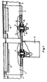
- Figure 1 shows two crash barriers 1 and 2, as they are in traffic e.g. B. used for securing highways are.
- These guard rails are opposite the usual arrangement there according to the invention pivoted so far about their longitudinal axes, with its broad side roughly horizontal lie, as can be seen particularly well from FIG.
- the Guardrails with their guide plates 1.1 and 1.2 serve as receptacles and attachment of only symbolically indicated in Figure 2
- Plastic cable trays 3 it is about them Elevation of the cable troughs in the areas where these cannot or should not be laid in the ground. For the Elevation of the cable troughs are not used in the drawing illustrated posts or supports using suitable adapters 5 attack the trailers.
- At least in the area of Joints of neighboring guardrails are the from Drawing apparent trailer 4 used there for electrically isolated mechanical definition of neighboring Guard rails 1 and 2 serve.
- the trailer extends for this each over a predetermined minimum width over the Joint area of the guardrails.
- Fixing the guardrails 1 and 2 on the trailer 4 happens z. B. by screws 6, the washers 7 and spring washers 8 with associated Nuts 9 work together.
- neighboring guardrails 1 and 2 are opposite the common trailers 4 arranged electrically isolated. This is done using specially designed spacers insulating material between the guardrails and the trailers, which is also the mechanical definition serve the guardrails.
- the arrangement can of course also be in such a way that the bushing and washer Intermediate piece compared to the arrangement shown 180 ° rotated is used, with the collar and the Disc from both sides to the guardrail profile nestle. Likewise, it is possible to use additional ones Disks both the trailer and the crash barriers to isolate from the fasteners.
- a socket with a circumferential collar can also be tubular Bushings without a collar can be used, the function the collar by at least one additional disc each insulating material is perceived.
- two Insulating disks that can be plugged onto sockets can also be used Intermediate layer with two spaced screws Recesses can be used.
- guardrails The electrically isolated arrangement of adjacent guardrails is required to ensure that any external voltage drops e.g. B. only due to torn catenary to the guardrail section directly affected by the fault are limited.
- the guard rails are not just for this to be isolated from the common trailers, but they must not have any other electrically conductive Have connection with each other. For this purpose there is a certain gap between the neighboring guardrails. This gap will at least become if the intermediate pieces have a relative movement of the guardrails towards the trailers, depending on the Change ambient temperature; then he also has that Function of an expansion joint.
- a floating storage of the This can result in guard rails against the common trailer achieved that the guardrails and / or the trailer Slots or slots for receiving the intermediate pieces have over which a relative movement of the crash barriers and the trailer is possible.
- the fastening of the crash barriers the trailers are in the yoke area 1.3 of the crash barrier, see above that the fasteners are not in the contact area of the Project cable trays.
- Each trailer consists of a U-shaped sheet metal bracket limited Width, the yoke via an adapter 5 to one Post or column can be set.
- This yoke is in the longitudinal direction of the crash barrier with at least two spaced recesses for receiving each provided an intermediate piece, each intermediate piece for electrical insulation and at the same time mechanical Definition of a guardrail end on the trailer serves.
- the legs 4.1 and 4.2 of the U-shaped bracket stand diagonally upwards and outwards and serve to guardrails to support in its edge area from the bottom.
- Each guardrail area isolated from neighboring guardrails can be properly grounded; This can done by grounding cables attached to a guardrail of a each guardrail area and at least one rail are connected.
- Each guardrail area can do this one or more electrically connected guardrails consist; are the guard rails of each guard rail area then without insulating spacers on the connecting them To attach semitrailers or by means of short-circuit connectors to contact.
Landscapes
- Details Of Indoor Wiring (AREA)
- Refuge Islands, Traffic Blockers, Or Guard Fence (AREA)
- Insulated Conductors (AREA)
- Patch Boards (AREA)
- Catching Or Destruction (AREA)
- Electric Cable Arrangement Between Relatively Moving Parts (AREA)
Applications Claiming Priority (2)
| Application Number | Priority Date | Filing Date | Title |
|---|---|---|---|
| DE29805653U DE29805653U1 (de) | 1998-03-23 | 1998-03-23 | Einrichtung zum Aufständern von Kunststoff-Kabeltrögen im Nahbereich elektrifizierter Bahnstrecken |
| DE29805653U | 1998-03-23 |
Publications (3)
| Publication Number | Publication Date |
|---|---|
| EP0945946A2 true EP0945946A2 (fr) | 1999-09-29 |
| EP0945946A3 EP0945946A3 (fr) | 1999-12-08 |
| EP0945946B1 EP0945946B1 (fr) | 2001-05-16 |
Family
ID=8054928
Family Applications (1)
| Application Number | Title | Priority Date | Filing Date |
|---|---|---|---|
| EP99250038A Expired - Lifetime EP0945946B1 (fr) | 1998-03-23 | 1999-02-05 | Dispositif pour supporter des caniveaux de câbles en matière synthétique à proximité de lignes de chemin de fer électrifiées |
Country Status (6)
| Country | Link |
|---|---|
| EP (1) | EP0945946B1 (fr) |
| AT (1) | ATE201290T1 (fr) |
| DE (2) | DE29805653U1 (fr) |
| DK (1) | DK0945946T3 (fr) |
| ES (1) | ES2158722T3 (fr) |
| NO (1) | NO321613B1 (fr) |
Families Citing this family (1)
| Publication number | Priority date | Publication date | Assignee | Title |
|---|---|---|---|---|
| DE102009036470B4 (de) * | 2009-08-03 | 2011-07-28 | UPZ Logistik & Consulting GmbH, 06796 | Mobiles Haltesystem für Kabeltröge |
Family Cites Families (2)
| Publication number | Priority date | Publication date | Assignee | Title |
|---|---|---|---|---|
| DE3447836A1 (de) * | 1984-12-29 | 1986-07-03 | Stahlwerke Peine-Salzgitter Ag, 3320 Salzgitter | Kabeltrog fuer gleisanlagen |
| DE59609170D1 (de) * | 1995-10-26 | 2002-06-06 | Dieter Otto Braig | Kabelkanal |
-
1998
- 1998-03-23 DE DE29805653U patent/DE29805653U1/de not_active Expired - Lifetime
-
1999
- 1999-02-05 DE DE59900091T patent/DE59900091D1/de not_active Expired - Fee Related
- 1999-02-05 AT AT99250038T patent/ATE201290T1/de not_active IP Right Cessation
- 1999-02-05 EP EP99250038A patent/EP0945946B1/fr not_active Expired - Lifetime
- 1999-02-05 ES ES99250038T patent/ES2158722T3/es not_active Expired - Lifetime
- 1999-02-05 DK DK99250038T patent/DK0945946T3/da active
- 1999-03-22 NO NO19991386A patent/NO321613B1/no unknown
Also Published As
| Publication number | Publication date |
|---|---|
| EP0945946A3 (fr) | 1999-12-08 |
| NO321613B1 (no) | 2006-06-12 |
| ATE201290T1 (de) | 2001-06-15 |
| DE59900091D1 (de) | 2001-06-21 |
| ES2158722T3 (es) | 2001-09-01 |
| DE29805653U1 (de) | 1998-07-16 |
| DK0945946T3 (da) | 2001-08-27 |
| NO991386D0 (no) | 1999-03-22 |
| NO991386L (no) | 1999-09-24 |
| EP0945946B1 (fr) | 2001-05-16 |
Similar Documents
| Publication | Publication Date | Title |
|---|---|---|
| EP3575176B1 (fr) | Véhicule ferroviaire pourvu de logement de câble | |
| DE102017100140A1 (de) | Elektrische Sammelschienenleitungsverbindung mit externen Schraubklemmstützen | |
| EP3936663A1 (fr) | Système de clôture de protection de rail | |
| EP0472847A2 (fr) | Glissière de sécurité routière pour retenir les véhicules | |
| EP0945946B1 (fr) | Dispositif pour supporter des caniveaux de câbles en matière synthétique à proximité de lignes de chemin de fer électrifiées | |
| DE3447836A1 (de) | Kabeltrog fuer gleisanlagen | |
| CH676218A5 (fr) | ||
| EP4070998A1 (fr) | Système d'accès pour un véhicule doté d'un caisson de marche modulaire, ainsi que véhicule | |
| WO2016139039A1 (fr) | Dispositif de court-circuit électrique | |
| DE69709387T2 (de) | Anordnung, verfahren und systemkomponent zum montage und wartung von anschlussmodulen in einen hochspannungsschalter | |
| DE19631995B4 (de) | System zum Verbinden einer Weicheisenstromschiene mit einem Stromleiter | |
| EP1287798A1 (fr) | Dispositif visant la fabrication des produits d'hygiène | |
| EP2036176A1 (fr) | Support de barres conductrices et unité distributrice de courant dotée d'un support de barres conductrices | |
| DE4139177A1 (de) | Verfahren zum errichten einer hochspannungsinnenstation mit luftisolation und auf diese weise erhaltene station | |
| DE3812507A1 (de) | Schaltfeld fuer eine gekapselte mittelspannungs-schaltanlage | |
| DE102019105511B3 (de) | Prellbock für Fahrschienen eines Gleises | |
| EP1826882B1 (fr) | Revêtement isolant pour une traverse de pylône de ligne électrique aérienne | |
| DE19626347C2 (de) | Oberleitung | |
| DE202020103948U1 (de) | Befestigungselement und Befestigungssystem zur Befestigung einer Gleiszusatzvorrichtung an einem Gleissystem sowie ein Gleisschutzzaunsystem | |
| EP0774814A2 (fr) | Elément pour fermer un poste à haute tension | |
| DE10224713A1 (de) | Flachkabel, Verfahren zur Reparatur des Flachkabels und Vorrichtung zur Durchführung des Verfahrens | |
| DE3011619C2 (de) | Schaltgeräteschrank für transportable Siganlanlagen | |
| DE4310667C2 (de) | Parkanlage für Kraftfahrzeuge | |
| DE10147342C2 (de) | Schaltschrank | |
| DE102024116609A1 (de) | Photovoltaik-Montagesystem |
Legal Events
| Date | Code | Title | Description |
|---|---|---|---|
| PUAI | Public reference made under article 153(3) epc to a published international application that has entered the european phase |
Free format text: ORIGINAL CODE: 0009012 |
|
| AK | Designated contracting states |
Kind code of ref document: A2 Designated state(s): AT DE DK ES FI GB IE IT NL SE |
|
| AX | Request for extension of the european patent |
Free format text: AL;LT;LV;MK;RO;SI |
|
| PUAL | Search report despatched |
Free format text: ORIGINAL CODE: 0009013 |
|
| AK | Designated contracting states |
Kind code of ref document: A3 Designated state(s): AT BE CH CY DE DK ES FI FR GB GR IE IT LI LU MC NL PT SE |
|
| AX | Request for extension of the european patent |
Free format text: AL;LT;LV;MK;RO;SI |
|
| 17P | Request for examination filed |
Effective date: 19991118 |
|
| GRAG | Despatch of communication of intention to grant |
Free format text: ORIGINAL CODE: EPIDOS AGRA |
|
| 17Q | First examination report despatched |
Effective date: 20000517 |
|
| AKX | Designation fees paid |
Free format text: AT DE DK ES FI GB IE IT NL SE |
|
| GRAG | Despatch of communication of intention to grant |
Free format text: ORIGINAL CODE: EPIDOS AGRA |
|
| GRAH | Despatch of communication of intention to grant a patent |
Free format text: ORIGINAL CODE: EPIDOS IGRA |
|
| GRAH | Despatch of communication of intention to grant a patent |
Free format text: ORIGINAL CODE: EPIDOS IGRA |
|
| GRAA | (expected) grant |
Free format text: ORIGINAL CODE: 0009210 |
|
| AK | Designated contracting states |
Kind code of ref document: B1 Designated state(s): AT DE DK ES FI GB IE IT NL SE |
|
| PG25 | Lapsed in a contracting state [announced via postgrant information from national office to epo] |
Ref country code: IT Free format text: LAPSE BECAUSE OF FAILURE TO SUBMIT A TRANSLATION OF THE DESCRIPTION OR TO PAY THE FEE WITHIN THE PRE;WARNING: LAPSES OF ITALIAN PATENTS WITH EFFECTIVE DATE BEFORE 2007 MAY HAVE OCCURRED AT ANY TIME BEFORE 2007. THE CORRECT EFFECTIVE DATE MAY BE DIFFERENT FROM THE ONE RECORDED.SCRIBED TIME-LIMIT Effective date: 20010516 Ref country code: IE Free format text: LAPSE BECAUSE OF FAILURE TO SUBMIT A TRANSLATION OF THE DESCRIPTION OR TO PAY THE FEE WITHIN THE PRESCRIBED TIME-LIMIT Effective date: 20010516 |
|
| REF | Corresponds to: |
Ref document number: 201290 Country of ref document: AT Date of ref document: 20010615 Kind code of ref document: T |
|
| REG | Reference to a national code |
Ref country code: IE Ref legal event code: FG4D Free format text: GERMAN |
|
| REF | Corresponds to: |
Ref document number: 59900091 Country of ref document: DE Date of ref document: 20010621 |
|
| REG | Reference to a national code |
Ref country code: DK Ref legal event code: T3 |
|
| REG | Reference to a national code |
Ref country code: ES Ref legal event code: FG2A Ref document number: 2158722 Country of ref document: ES Kind code of ref document: T3 |
|
| GBT | Gb: translation of ep patent filed (gb section 77(6)(a)/1977) |
Effective date: 20010814 |
|
| REG | Reference to a national code |
Ref country code: GB Ref legal event code: IF02 |
|
| REG | Reference to a national code |
Ref country code: IE Ref legal event code: FD4D |
|
| PLBE | No opposition filed within time limit |
Free format text: ORIGINAL CODE: 0009261 |
|
| STAA | Information on the status of an ep patent application or granted ep patent |
Free format text: STATUS: NO OPPOSITION FILED WITHIN TIME LIMIT |
|
| 26N | No opposition filed | ||
| PGFP | Annual fee paid to national office [announced via postgrant information from national office to epo] |
Ref country code: FI Payment date: 20070111 Year of fee payment: 9 |
|
| PGFP | Annual fee paid to national office [announced via postgrant information from national office to epo] |
Ref country code: AT Payment date: 20070112 Year of fee payment: 9 |
|
| PGFP | Annual fee paid to national office [announced via postgrant information from national office to epo] |
Ref country code: SE Payment date: 20070208 Year of fee payment: 9 Ref country code: GB Payment date: 20070208 Year of fee payment: 9 Ref country code: DK Payment date: 20070208 Year of fee payment: 9 |
|
| PGFP | Annual fee paid to national office [announced via postgrant information from national office to epo] |
Ref country code: NL Payment date: 20070212 Year of fee payment: 9 |
|
| PGFP | Annual fee paid to national office [announced via postgrant information from national office to epo] |
Ref country code: ES Payment date: 20070315 Year of fee payment: 9 |
|
| PGFP | Annual fee paid to national office [announced via postgrant information from national office to epo] |
Ref country code: DE Payment date: 20070420 Year of fee payment: 9 |
|
| REG | Reference to a national code |
Ref country code: DK Ref legal event code: EBP |
|
| EUG | Se: european patent has lapsed | ||
| GBPC | Gb: european patent ceased through non-payment of renewal fee |
Effective date: 20080205 |
|
| PG25 | Lapsed in a contracting state [announced via postgrant information from national office to epo] |
Ref country code: FI Free format text: LAPSE BECAUSE OF NON-PAYMENT OF DUE FEES Effective date: 20080205 |
|
| NLV4 | Nl: lapsed or anulled due to non-payment of the annual fee |
Effective date: 20080901 |
|
| PG25 | Lapsed in a contracting state [announced via postgrant information from national office to epo] |
Ref country code: NL Free format text: LAPSE BECAUSE OF NON-PAYMENT OF DUE FEES Effective date: 20080901 Ref country code: AT Free format text: LAPSE BECAUSE OF NON-PAYMENT OF DUE FEES Effective date: 20080205 |
|
| PG25 | Lapsed in a contracting state [announced via postgrant information from national office to epo] |
Ref country code: SE Free format text: LAPSE BECAUSE OF NON-PAYMENT OF DUE FEES Effective date: 20080206 Ref country code: DK Free format text: LAPSE BECAUSE OF NON-PAYMENT OF DUE FEES Effective date: 20080229 Ref country code: DE Free format text: LAPSE BECAUSE OF NON-PAYMENT OF DUE FEES Effective date: 20080902 |
|
| REG | Reference to a national code |
Ref country code: ES Ref legal event code: FD2A Effective date: 20080206 |
|
| PG25 | Lapsed in a contracting state [announced via postgrant information from national office to epo] |
Ref country code: GB Free format text: LAPSE BECAUSE OF NON-PAYMENT OF DUE FEES Effective date: 20080205 |
|
| PG25 | Lapsed in a contracting state [announced via postgrant information from national office to epo] |
Ref country code: ES Free format text: LAPSE BECAUSE OF NON-PAYMENT OF DUE FEES Effective date: 20080206 |