EP0945973A2 - Dispositif de commande pour un moteur synchrone monophase - Google Patents
Dispositif de commande pour un moteur synchrone monophase Download PDFInfo
- Publication number
- EP0945973A2 EP0945973A2 EP99105656A EP99105656A EP0945973A2 EP 0945973 A2 EP0945973 A2 EP 0945973A2 EP 99105656 A EP99105656 A EP 99105656A EP 99105656 A EP99105656 A EP 99105656A EP 0945973 A2 EP0945973 A2 EP 0945973A2
- Authority
- EP
- European Patent Office
- Prior art keywords
- voltage
- control electronics
- rotor
- stator winding
- switch
- Prior art date
- Legal status (The legal status is an assumption and is not a legal conclusion. Google has not performed a legal analysis and makes no representation as to the accuracy of the status listed.)
- Granted
Links
Images


Classifications
-
- H—ELECTRICITY
- H02—GENERATION; CONVERSION OR DISTRIBUTION OF ELECTRIC POWER
- H02P—CONTROL OR REGULATION OF ELECTRIC MOTORS, ELECTRIC GENERATORS OR DYNAMO-ELECTRIC CONVERTERS; CONTROLLING TRANSFORMERS, REACTORS OR CHOKE COILS
- H02P6/00—Arrangements for controlling synchronous motors or other dynamo-electric motors using electronic commutation dependent on the rotor position; Electronic commutators therefor
- H02P6/20—Arrangements for starting
- H02P6/22—Arrangements for starting in a selected direction of rotation
-
- H—ELECTRICITY
- H02—GENERATION; CONVERSION OR DISTRIBUTION OF ELECTRIC POWER
- H02P—CONTROL OR REGULATION OF ELECTRIC MOTORS, ELECTRIC GENERATORS OR DYNAMO-ELECTRIC CONVERTERS; CONTROLLING TRANSFORMERS, REACTORS OR CHOKE COILS
- H02P1/00—Arrangements for starting electric motors or dynamo-electric converters
- H02P1/16—Arrangements for starting electric motors or dynamo-electric converters for starting dynamo-electric motors or dynamo-electric converters
- H02P1/46—Arrangements for starting electric motors or dynamo-electric converters for starting dynamo-electric motors or dynamo-electric converters for starting an individual synchronous motor
- H02P1/465—Arrangements for starting electric motors or dynamo-electric converters for starting dynamo-electric motors or dynamo-electric converters for starting an individual synchronous motor for starting an individual single-phase synchronous motor
Definitions
- the invention relates to a device for controlling the Start-up and operation of a non-self-starting Single-phase synchronous motor, at least one of which Stator winding via one of control electronics controlled switch to the AC voltage of a network is switchable.
- Such a device is for starting one Single-phase synchronous motor necessary because of its comparatively high power, for example> 50 W, due to the design when applying the AC voltage to the network does not start by itself and that in a certain Direction of rotation should start.
- Such synchronous motors will be for example in household machines, especially for Water pumps for dishwashers used.
- a device of the type mentioned is from the EP 0 654 890 B1 known. There is to capture the a position sensor is required for the respective position of the rotor, which is, for example, a Hall sensor. Dependent on from the sensor signal and the respective polarity of the AC voltage, the switch (triac) is ignited when the current based on the switched AC voltage with the respective orientation of the magnetic field of the Rotors a torque in the direction of the desired one Direction of rotation results.
- a position sensor is in terms of structure and the assembly is complex. It must be integrated in the engine and be connected to the control electronics.
- EP 0 691 732 B1 describes an inverter for one Single-phase synchronous motor described, for example can be used for the pump drive in a dishwasher is.
- DE 40 33 121 A1 describes a device for starting an electric single-phase synchronous motor known is only designed for comparatively small outputs and is self-starting.
- DE 40 33 121 A1 describes a way in a synchronous motor Desired direction of rotation without mechanical backstop to start.
- the device according to DE 40 33 121 A1 is unsuitable, because such due to their inertia Target speed could be accelerated and with small Movements with mains frequency stopped.
- EP 0 495 611 A2 describes a device for starting of a 3-phase motor for a magnetic disk described. The is only used to control the target speed induced voltage in the windings or the electromotive force evaluated.
- DE 44 18 721 A1 describes a control method for a lye circulation pump of a dishwasher known. It is not meant to promote the continuous self-priming pump can be monitored. Speed fluctuations and fluctuations in the motor current are processed to influence the program flow.
- the object of the invention is a device of to propose the type mentioned at the beginning, with which a not self-starting single-phase synchronous motor in correct direction of rotation can be started without a sensor is necessary, which detects the position of the rotor.
- the above object is characterized by the features of characterizing part of claim 1 solved.
- a torque is created in the desired direction of rotation then when the induced voltage and the respective Mains half wave or the corresponding current the same Have polarity. It can also be from the control electronics evaluated the slope of the induced voltage (EMF) to start up the motor to synchronous speed to even out.
- EMF induced voltage
- EMF induced voltage
- a single-phase synchronous motor 2 for example the Serves drive a water pump of a dishwasher, points a stator winding 1 on an electronic Switch 3, in particular triac or optically triggerable Triac, can be switched to the AC network 4.
- the Switch 3 controls control electronics 5 that for example with a microprocessor or Microcontroller works and is part of a program control device can be.
- the control electronics 5 evaluates the via an input 6 respective polarity of the respective network half-waves and via an input 7 to the stator winding 1 falling voltage Um or E as follows:
- the motor current I is the same Zero.
- the permanent magnetic rotor 8 does not remain stand immediately, but turns because of it Mass inertia continues, whereby in the stator winding 1 a voltage corresponding to the EMF is induced. At least their polarity is determined by the control electronics 5 evaluated.
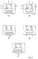
- the motor 2 has stator poles 9, 10 which form asymmetrical air gap constrictions 11, 12 (cf. Fig.2).
- the rotor 8 can thereby be de-energized the stator winding 1 only because of the reluctance moments one or the other rest position (cf. Fig. 2a or Fig.2b), but no dead center position.
- the desired starting position is shown in Figure 2d.
- To the Stator winding 1 is at least one voltage pulse one, for example negative, polarity. Stands the rotor 8 in the rest position a, then it rotates due to the voltage pulse by about 45 ° in the position of Figure 2c. Then in the currentless state the stator winding 1, the rotor 8 pivots about again 45 ° back (see Fig.2d). So at position a nothing changed in the end result that is appropriate because the rest position a and the start position d are the same.
- the voltage pulses required to reach the start position need not be whole half-waves. Around to avoid demagnetization of the rotor cut half waves.
- the first voltage pulses can have a smaller amplitude have voltage pulses as following so it doesn't overflowing the starting position comes what special could be the case from the rest position b.
- the voltage pulses mentioned are from the Control electronics 5 created via the switch 3.
- the Figures 3 and 4 show current and voltage diagrams for setting the starting position, starting and the Motor 2 starts up to synchronous speed.
- the control electronics 5 receives for example from a program control device Command to switch on the motor 2. Then at negative half-waves of switch 3, especially triac, ignited. This results in the stator winding 1 Current pulses of negative polarity, through which the rotor 8 to its starting position in the manner described above brought. In Figures 3 and 4 there are four such Current pulses shown. However, more can be done fewer current pulses are switched. Again switched so many current pulses that reaching the Starting position (see FIG. 2d) is safe.
- the control electronics 5 detects the in the de-energized state Stator winding 1, the induced voltage E and Network half-wave polarity. Have or reach them induced voltage E and the mains voltage U same Sign, then the switch 3 of the Control electronics 5 switched on, so that the Stator winding 1 is subjected to current accordingly. This is the case with the diagrams according to FIGS. 3, 4 Switch-on times t3 to t8 the case. At each Switch 3 blocks the next zero crossing of the current again. It follows that in successive half-waves of both polarities predominantly a torque in the correct direction of rotation of the engine 2 arises. To the engine-related Phase shift between current and voltage too the control electronics can take the slope into account the induced voltage and the switch switch ahead. This makes it possible to start up equalize the rotor.
- the control electronics 5 through the Evaluation of the induced voltage E (EMF) operation optimize for maximum efficiency. To do this, she measures the induced voltage E in the de-energized times of Stator winding 1 and calculates the phase position of the induced voltage E. The control of the switch 3 then takes place so that the fundamental wave of the motor current I assumes the same phase position as the induced voltage.
- EMF induced voltage
- characteristic data of the motor 2 and the load to be driven In the control electronics 5, characteristic data of the motor 2 and the load to be driven. About the Current pulse duration set at high efficiency the respective load state of the engine 2 be recognized. It can be done with the described measurement of the EMF of the motor 2 also Malfunctions, for example wrong direction of rotation or Detect running without load or blocking motor 2.
- the control electronics 5 can then special to remedy the fault Take action. For example, it can be an aggregate briefly activate the reversal of the direction of rotation of the Pump is used to remove their blockage. It is also possible that the control electronics 5 if they have a Blockage of the pump detects a restart of the pump activated.
- control electronics 5 if one Idling of the pump detects that the in currentless state affects measurable induced voltage a shutdown of the engine 2 and / or activation of another aggregate that counteracts your idling - refill water, for example - activated.
- Control electronics 5 can then be described in the Respond by stopping the engine 2 and / or another unit of the machine activates what counteracts this disorder.
Landscapes
- Engineering & Computer Science (AREA)
- Power Engineering (AREA)
- Control Of Motors That Do Not Use Commutators (AREA)
- Control Of Ac Motors In General (AREA)
- Motor And Converter Starters (AREA)
Applications Claiming Priority (2)
| Application Number | Priority Date | Filing Date | Title |
|---|---|---|---|
| DE19813095 | 1998-03-25 | ||
| DE19813095A DE19813095A1 (de) | 1998-03-25 | 1998-03-25 | Vorrichtung zum Steuern eines Einphasen-Synchronmotors |
Publications (3)
| Publication Number | Publication Date |
|---|---|
| EP0945973A2 true EP0945973A2 (fr) | 1999-09-29 |
| EP0945973A3 EP0945973A3 (fr) | 2001-06-13 |
| EP0945973B1 EP0945973B1 (fr) | 2002-06-26 |
Family
ID=7862248
Family Applications (1)
| Application Number | Title | Priority Date | Filing Date |
|---|---|---|---|
| EP99105656A Expired - Lifetime EP0945973B1 (fr) | 1998-03-25 | 1999-03-19 | Dispositif de commande pour un moteur synchrone monophase |
Country Status (3)
| Country | Link |
|---|---|
| EP (1) | EP0945973B1 (fr) |
| DE (2) | DE19813095A1 (fr) |
| ES (1) | ES2179568T3 (fr) |
Cited By (22)
| Publication number | Priority date | Publication date | Assignee | Title |
|---|---|---|---|---|
| EP1443635A1 (fr) * | 2003-01-21 | 2004-08-04 | Grundfos A/S | Procédé de contrôle d'un angle de déclenchement |
| EP1154558A3 (fr) * | 2000-05-12 | 2004-11-17 | Aradex AG | Procédé pour commander un moteur synchrone |
| WO2009001291A3 (fr) * | 2007-06-26 | 2009-04-09 | Askoll P & C S R L | Système de contrôle dépourvu de capteurs de position pour moteur électrique synchrone |
| EP1387087A3 (fr) * | 2002-07-29 | 2009-10-28 | Wilo Ag | Méthode pour déterminer le débit d'une pompe |
| JP2010503367A (ja) * | 2006-09-04 | 2010-01-28 | ウェリントン ドライブ テクノロジーズ リミテッド | 同期式電気機械の制御 |
| ITPD20080313A1 (it) * | 2008-10-29 | 2010-04-30 | Newa Tecno Ind S R L | Dispositivo elettronico di avviamento e controllo per motori elettrici sincroni monofase con rotore a magneti permanenti |
| ITTO20090166A1 (it) * | 2009-03-04 | 2010-09-05 | Askoll P & C S R L | Procedimento per il monitoraggio del carico di un motore elettrico sincrono in corrente alternata con rotore a magneti permanenti |
| FR2951267A1 (fr) * | 2009-10-14 | 2011-04-15 | Peugeot Citroen Automobiles Sa | Dispositif de detection du niveau de liquide dans un reservoir |
| EP2410651A1 (fr) * | 2010-07-23 | 2012-01-25 | Askoll Holding S.r.l. | Méthode pour le démarrage d'un Moteur électrique synchrone monophasé à aimant permanent et dispositif électronique de mise en oeuvre dudit procédé |
| EP2439840A1 (fr) * | 2010-10-11 | 2012-04-11 | Askoll Holding S.r.l. | Procédé de régulation d'une pompe d'écoulement d'un appareil ménager et l'unité de traitement pour exécuter ce procédé |
| CN102904510A (zh) * | 2011-07-25 | 2013-01-30 | 阿思科尔控股责任有限公司 | 永磁单相同步电动机启动方法及实现该方法的电子设备 |
| EP3222853A3 (fr) * | 2016-03-22 | 2018-01-10 | Whirlpool Corporation | Système d'écoulement de fluide à plusieurs sorties pour un appareil comprenant un moteur bidirectionnel |
| EP3447903A1 (fr) * | 2017-08-25 | 2019-02-27 | Johnson Electric International AG | Circuit d'entraînement de moteur, procédé d'entraînement de moteur et moteur l'utilisant |
| US10234065B2 (en) | 2015-10-27 | 2019-03-19 | Whirlpool Corporation | Collet securing device for joining two fluid lines and providing lateral support at the connection of the two fluid lines |
| US10480117B2 (en) | 2017-02-27 | 2019-11-19 | Whirlpool Corporation | Self cleaning sump cover |
| US10619289B2 (en) | 2017-02-27 | 2020-04-14 | Whirlpool Corporation | Self cleaning diverter valve |
| US10634412B2 (en) | 2017-04-10 | 2020-04-28 | Whirlpool Corporation | Concealed upstream air tower guide vanes |
| US10655266B2 (en) | 2016-11-30 | 2020-05-19 | Whirlpool Corporation | Lint processing fluid pump for a laundry appliance |
| US10662574B2 (en) | 2017-02-27 | 2020-05-26 | Whirlpool Corporation | Self cleaning heater exchanger plate |
| US10697700B2 (en) | 2018-01-17 | 2020-06-30 | Whirlpool Corporation | Refrigeration water dispensing system |
| IT202100026357A1 (it) * | 2021-10-15 | 2022-01-15 | Fise Spa | Metodo per l’avviamento e il controllo di un motore brushless monofase |
| EP4156496A1 (fr) * | 2021-09-28 | 2023-03-29 | Miele & Cie. KG | Système d'entraînement |
Family Cites Families (6)
| Publication number | Priority date | Publication date | Assignee | Title |
|---|---|---|---|---|
| JPS61240868A (ja) * | 1985-04-16 | 1986-10-27 | Matsushita Seiko Co Ltd | 同期モ−タ−の制御装置 |
| DE3638440A1 (de) * | 1986-11-11 | 1988-06-01 | Bosch Gmbh Robert | Einphasenmaschine |
| FR2653613B1 (fr) * | 1989-10-20 | 1994-11-18 | Eaton Controls Sa | Procede et dispositif pour le demarrage d'un moteur electrique synchrone monophase. |
| ES2097599T5 (es) * | 1993-11-22 | 2003-04-01 | Bsh Bosch Siemens Hausgeraete | Dispositivo para el accionamiento de un motor sincrono monofasico, en especial para el accionamiento de una bomba en un aparato electrodomestico. |
| AT402869B (de) * | 1994-02-03 | 1997-09-25 | Muehlegger Werner Dr | Elektronische startvorrichtung zum starten einer einphasigen synchronmaschine |
| IT1269755B (it) * | 1994-05-11 | 1997-04-15 | Sisme | Dispositivo elettronico per l'avviamento e controllo di un motore sincrono monofase a magneti permanenti |
-
1998
- 1998-03-25 DE DE19813095A patent/DE19813095A1/de not_active Withdrawn
-
1999
- 1999-03-19 ES ES99105656T patent/ES2179568T3/es not_active Expired - Lifetime
- 1999-03-19 EP EP99105656A patent/EP0945973B1/fr not_active Expired - Lifetime
- 1999-03-19 DE DE59901834T patent/DE59901834D1/de not_active Expired - Lifetime
Cited By (42)
| Publication number | Priority date | Publication date | Assignee | Title |
|---|---|---|---|---|
| EP1154558A3 (fr) * | 2000-05-12 | 2004-11-17 | Aradex AG | Procédé pour commander un moteur synchrone |
| EP1387087A3 (fr) * | 2002-07-29 | 2009-10-28 | Wilo Ag | Méthode pour déterminer le débit d'une pompe |
| WO2004066484A1 (fr) * | 2003-01-21 | 2004-08-05 | Grundfos A/S | Procede pour commander des angles d'avance |
| EP1443635A1 (fr) * | 2003-01-21 | 2004-08-04 | Grundfos A/S | Procédé de contrôle d'un angle de déclenchement |
| JP2010503367A (ja) * | 2006-09-04 | 2010-01-28 | ウェリントン ドライブ テクノロジーズ リミテッド | 同期式電気機械の制御 |
| EP2060002A4 (fr) * | 2006-09-04 | 2010-08-11 | Wellington Drive Technologies | Commande de machines électriques synchrones |
| US8120297B2 (en) | 2006-09-04 | 2012-02-21 | Wellington Drive Technologies Limited | Control of synchronous electrical machines |
| KR101437716B1 (ko) * | 2007-06-26 | 2014-09-18 | 아스콜 피 앤 씨 에스.알.엘. | 동기식 전기 모터를 위한 위치 센서가 없는 제어 시스템 |
| WO2009001291A3 (fr) * | 2007-06-26 | 2009-04-09 | Askoll P & C S R L | Système de contrôle dépourvu de capteurs de position pour moteur électrique synchrone |
| CN101711453B (zh) * | 2007-06-26 | 2012-05-30 | 阿思科尔P&C责任有限公司 | 用于同步电动机的不带有位置传感器的控制系统 |
| US8222856B2 (en) | 2007-06-26 | 2012-07-17 | Askoll P&C S.R.L. | Control system without position sensors for a synchronous electric motor |
| ITPD20080313A1 (it) * | 2008-10-29 | 2010-04-30 | Newa Tecno Ind S R L | Dispositivo elettronico di avviamento e controllo per motori elettrici sincroni monofase con rotore a magneti permanenti |
| ITTO20090166A1 (it) * | 2009-03-04 | 2010-09-05 | Askoll P & C S R L | Procedimento per il monitoraggio del carico di un motore elettrico sincrono in corrente alternata con rotore a magneti permanenti |
| FR2951267A1 (fr) * | 2009-10-14 | 2011-04-15 | Peugeot Citroen Automobiles Sa | Dispositif de detection du niveau de liquide dans un reservoir |
| EP2410651A1 (fr) * | 2010-07-23 | 2012-01-25 | Askoll Holding S.r.l. | Méthode pour le démarrage d'un Moteur électrique synchrone monophasé à aimant permanent et dispositif électronique de mise en oeuvre dudit procédé |
| US8164286B2 (en) | 2010-07-23 | 2012-04-24 | Askoll Holding S.R.L. | Method for starting a permanent magnet single-phase synchronous electric motor and electronic device for implementing said method |
| CN102347723A (zh) * | 2010-07-23 | 2012-02-08 | 阿思科尔控股责任有限公司 | 启动永磁单相同步电机的方法及实施其的电子装置 |
| CN102347723B (zh) * | 2010-07-23 | 2015-06-10 | 阿思科尔控股责任有限公司 | 启动永磁单相同步电机的方法及实施其的电子装置 |
| US9065363B2 (en) | 2010-07-23 | 2015-06-23 | Askoll Holding S.R.L. | Method for starting a permanent magnet single-phase synchronous electric motor and electronic device for implementing said method |
| EP2421144A3 (fr) * | 2010-07-23 | 2016-01-06 | Askoll Holding S.r.l. | Méthode pour le démarrage d'un moteur électrique synchrone monophasé à aimant permanent et dispositif électronique de mise en oeuvre dudit procédé |
| CN102444570A (zh) * | 2010-10-11 | 2012-05-09 | 艾斯科尔侯丁有限公司 | 家用电器排放泵的控制方法以及实施该方法的处理单元 |
| EP2439840A1 (fr) * | 2010-10-11 | 2012-04-11 | Askoll Holding S.r.l. | Procédé de régulation d'une pompe d'écoulement d'un appareil ménager et l'unité de traitement pour exécuter ce procédé |
| US8766580B2 (en) | 2010-10-11 | 2014-07-01 | Askoll Holding S.R.L. | Method for controlling the discharge pump of a household appliance and processing unit for implementing said method |
| CN102904510A (zh) * | 2011-07-25 | 2013-01-30 | 阿思科尔控股责任有限公司 | 永磁单相同步电动机启动方法及实现该方法的电子设备 |
| CN102904510B (zh) * | 2011-07-25 | 2016-05-18 | 阿思科尔控股责任有限公司 | 永磁单相同步电动机启动方法及实现该方法的电子设备 |
| US10234065B2 (en) | 2015-10-27 | 2019-03-19 | Whirlpool Corporation | Collet securing device for joining two fluid lines and providing lateral support at the connection of the two fluid lines |
| EP3222853A3 (fr) * | 2016-03-22 | 2018-01-10 | Whirlpool Corporation | Système d'écoulement de fluide à plusieurs sorties pour un appareil comprenant un moteur bidirectionnel |
| US10557469B2 (en) | 2016-03-22 | 2020-02-11 | Whirlpool Corporation | Multi-outlet fluid flow system for an appliance incorporating a bi-directional motor |
| US10655266B2 (en) | 2016-11-30 | 2020-05-19 | Whirlpool Corporation | Lint processing fluid pump for a laundry appliance |
| US11603615B2 (en) | 2017-02-27 | 2023-03-14 | Whirlpool Corporation | Self cleaning sump cover |
| US10480117B2 (en) | 2017-02-27 | 2019-11-19 | Whirlpool Corporation | Self cleaning sump cover |
| US10619289B2 (en) | 2017-02-27 | 2020-04-14 | Whirlpool Corporation | Self cleaning diverter valve |
| US10662574B2 (en) | 2017-02-27 | 2020-05-26 | Whirlpool Corporation | Self cleaning heater exchanger plate |
| US11035073B2 (en) | 2017-02-27 | 2021-06-15 | Whirlpool Corporation | Self cleaning sump cover |
| US11802360B2 (en) | 2017-02-27 | 2023-10-31 | Whirlpool Corporation | Self cleaning sump cover |
| US10634412B2 (en) | 2017-04-10 | 2020-04-28 | Whirlpool Corporation | Concealed upstream air tower guide vanes |
| EP3447903A1 (fr) * | 2017-08-25 | 2019-02-27 | Johnson Electric International AG | Circuit d'entraînement de moteur, procédé d'entraînement de moteur et moteur l'utilisant |
| US10707787B2 (en) | 2017-08-25 | 2020-07-07 | Johnson Electric International AG | Motor driving circuit, motor driving method, and motor utilizing the same |
| US10697700B2 (en) | 2018-01-17 | 2020-06-30 | Whirlpool Corporation | Refrigeration water dispensing system |
| US11592232B2 (en) | 2018-01-17 | 2023-02-28 | Whirlpool Corporation | Refrigeration water dispensing system |
| EP4156496A1 (fr) * | 2021-09-28 | 2023-03-29 | Miele & Cie. KG | Système d'entraînement |
| IT202100026357A1 (it) * | 2021-10-15 | 2022-01-15 | Fise Spa | Metodo per l’avviamento e il controllo di un motore brushless monofase |
Also Published As
| Publication number | Publication date |
|---|---|
| EP0945973B1 (fr) | 2002-06-26 |
| EP0945973A3 (fr) | 2001-06-13 |
| DE59901834D1 (de) | 2002-08-01 |
| ES2179568T3 (es) | 2003-01-16 |
| DE19813095A1 (de) | 1999-09-30 |
Similar Documents
| Publication | Publication Date | Title |
|---|---|---|
| EP0945973B1 (fr) | Dispositif de commande pour un moteur synchrone monophase | |
| DE69727651T2 (de) | Vorrichtung zur Steuerung eines Synchronomotors mit einem Dauermagnetläufer | |
| DE69505298T2 (de) | Elektronische Schaltung zum Anlaufen und Steuern eines einphasigen Synchronmotors mit Permanentmagneten. | |
| EP3413458B1 (fr) | Commande pour moteur synchrone monophasé | |
| WO1998036123A2 (fr) | Appareil de traitement de lessive avec un moteur d'entrainement monte sur l'arbre du tambour | |
| DE19701856A1 (de) | Elektronische Anlauf und Betriebssteuerung für einen Einphasen-Synchronmotor | |
| EP0957570B1 (fr) | Dispositif pour commander un moteur synchrone monophasé | |
| DE19539656A1 (de) | Verfahren zum Anlaufen drehzahlveränderlicher elektrischer Antriebe | |
| EP0654890B2 (fr) | Dispositif pour entraíner un moteur synchrone monophasé en particulier pour entraínement d'un pompe dans un appareil ménager | |
| DE2755333C2 (fr) | ||
| DE602005004418T2 (de) | Ansteuerschaltung für einen elektrischen synchronmotor | |
| EP1443635B1 (fr) | Procédé de contrôle d'un angle d'allumage et moteur électrique alimenté en courant monophasé | |
| DE10014174A1 (de) | Bremsmodul | |
| DE102016114030A1 (de) | Integrierte Schaltung, Treiberschaltung für einen Motor, Motoranordnung und Geräteausrüstung damit | |
| DE9407983U1 (de) | Vorrichtung zum Antrieb eines Einphasen-Synchronmotors, insbesondere zum Antrieb eines Pumpenantriebes in einem Haushaltsgerät | |
| AT402869B (de) | Elektronische startvorrichtung zum starten einer einphasigen synchronmaschine | |
| EP3331157B1 (fr) | Procédé et unité de commande permettant de commander un moteur à réluctance commuté | |
| DE69622515T2 (de) | Gerät und Verfahren zur Verringerung der Eisenverluste in einer geschalteten Reluktanzmaschine | |
| EP1508810A1 (fr) | Circuit de commande pour un moteur à réluctance à commutation électronique | |
| DE2217847A1 (de) | Schaltungsanordnung zum umkehren der drehrichtung eines elektromotors insbesondere einer waschmaschine | |
| BE1029031B1 (de) | Verfahren zur thermischen Überwachung eines mindestens zweiphasigen bürstenlosen Motors | |
| DE3607162A1 (de) | Wechselstrommotor fuer insbesondere umwaelzpumpen | |
| EP3301807A1 (fr) | Entraînement synchronisé à deux brins | |
| DE1918257A1 (de) | Buersten- und kommutatorloser 3-Phasen-Wechselstrommotor mit veraenderbarer Drehzahl | |
| DE19953265A1 (de) | Verfahren zum Anfahren eines Gleichstrommotors |
Legal Events
| Date | Code | Title | Description |
|---|---|---|---|
| PUAI | Public reference made under article 153(3) epc to a published international application that has entered the european phase |
Free format text: ORIGINAL CODE: 0009012 |
|
| AK | Designated contracting states |
Kind code of ref document: A2 Designated state(s): DE ES FR GB IT |
|
| AX | Request for extension of the european patent |
Free format text: AL;LT;LV;MK;RO;SI |
|
| RAP1 | Party data changed (applicant data changed or rights of an application transferred) |
Owner name: DIEHL AKO STIFTUNG & CO. KG |
|
| PUAL | Search report despatched |
Free format text: ORIGINAL CODE: 0009013 |
|
| AK | Designated contracting states |
Kind code of ref document: A3 Designated state(s): AT BE CH CY DE DK ES FI FR GB GR IE IT LI LU MC NL PT SE |
|
| AX | Request for extension of the european patent |
Free format text: AL;LT;LV;MK;RO;SI |
|
| 17P | Request for examination filed |
Effective date: 20010509 |
|
| GRAG | Despatch of communication of intention to grant |
Free format text: ORIGINAL CODE: EPIDOS AGRA |
|
| 17Q | First examination report despatched |
Effective date: 20010905 |
|
| GRAG | Despatch of communication of intention to grant |
Free format text: ORIGINAL CODE: EPIDOS AGRA |
|
| GRAH | Despatch of communication of intention to grant a patent |
Free format text: ORIGINAL CODE: EPIDOS IGRA |
|
| AKX | Designation fees paid |
Free format text: DE ES FR GB IT |
|
| GRAH | Despatch of communication of intention to grant a patent |
Free format text: ORIGINAL CODE: EPIDOS IGRA |
|
| GRAA | (expected) grant |
Free format text: ORIGINAL CODE: 0009210 |
|
| AK | Designated contracting states |
Kind code of ref document: B1 Designated state(s): DE ES FR GB IT |
|
| REG | Reference to a national code |
Ref country code: GB Ref legal event code: FG4D Free format text: NOT ENGLISH |
|
| REF | Corresponds to: |
Ref document number: 59901834 Country of ref document: DE Date of ref document: 20020801 |
|
| GBT | Gb: translation of ep patent filed (gb section 77(6)(a)/1977) |
Effective date: 20020925 |
|
| ET | Fr: translation filed | ||
| REG | Reference to a national code |
Ref country code: ES Ref legal event code: FG2A Ref document number: 2179568 Country of ref document: ES Kind code of ref document: T3 |
|
| PLBE | No opposition filed within time limit |
Free format text: ORIGINAL CODE: 0009261 |
|
| STAA | Information on the status of an ep patent application or granted ep patent |
Free format text: STATUS: NO OPPOSITION FILED WITHIN TIME LIMIT |
|
| 26N | No opposition filed |
Effective date: 20030327 |
|
| PGFP | Annual fee paid to national office [announced via postgrant information from national office to epo] |
Ref country code: FR Payment date: 20050128 Year of fee payment: 7 |
|
| PGFP | Annual fee paid to national office [announced via postgrant information from national office to epo] |
Ref country code: ES Payment date: 20050301 Year of fee payment: 7 |
|
| PGFP | Annual fee paid to national office [announced via postgrant information from national office to epo] |
Ref country code: GB Payment date: 20050311 Year of fee payment: 7 |
|
| PG25 | Lapsed in a contracting state [announced via postgrant information from national office to epo] |
Ref country code: GB Free format text: LAPSE BECAUSE OF NON-PAYMENT OF DUE FEES Effective date: 20060319 |
|
| PG25 | Lapsed in a contracting state [announced via postgrant information from national office to epo] |
Ref country code: ES Free format text: LAPSE BECAUSE OF NON-PAYMENT OF DUE FEES Effective date: 20060321 |
|
| PGFP | Annual fee paid to national office [announced via postgrant information from national office to epo] |
Ref country code: IT Payment date: 20060331 Year of fee payment: 8 |
|
| GBPC | Gb: european patent ceased through non-payment of renewal fee |
Effective date: 20060319 |
|
| REG | Reference to a national code |
Ref country code: FR Ref legal event code: ST Effective date: 20061130 |
|
| REG | Reference to a national code |
Ref country code: ES Ref legal event code: FD2A Effective date: 20060321 |
|
| PG25 | Lapsed in a contracting state [announced via postgrant information from national office to epo] |
Ref country code: FR Free format text: LAPSE BECAUSE OF NON-PAYMENT OF DUE FEES Effective date: 20060331 |
|
| PG25 | Lapsed in a contracting state [announced via postgrant information from national office to epo] |
Ref country code: IT Free format text: LAPSE BECAUSE OF NON-PAYMENT OF DUE FEES Effective date: 20070319 |
|
| PGFP | Annual fee paid to national office [announced via postgrant information from national office to epo] |
Ref country code: DE Payment date: 20100519 Year of fee payment: 12 |
|
| PG25 | Lapsed in a contracting state [announced via postgrant information from national office to epo] |
Ref country code: DE Free format text: LAPSE BECAUSE OF NON-PAYMENT OF DUE FEES Effective date: 20111001 |
|
| REG | Reference to a national code |
Ref country code: DE Ref legal event code: R119 Ref document number: 59901834 Country of ref document: DE Effective date: 20111001 |