EP0946037A1 - Mobiles Notrufgerät - Google Patents
Mobiles Notrufgerät Download PDFInfo
- Publication number
- EP0946037A1 EP0946037A1 EP98105494A EP98105494A EP0946037A1 EP 0946037 A1 EP0946037 A1 EP 0946037A1 EP 98105494 A EP98105494 A EP 98105494A EP 98105494 A EP98105494 A EP 98105494A EP 0946037 A1 EP0946037 A1 EP 0946037A1
- Authority
- EP
- European Patent Office
- Prior art keywords
- emergency call
- emergency
- button
- call method
- call device
- Prior art date
- Legal status (The legal status is an assumption and is not a legal conclusion. Google has not performed a legal analysis and makes no representation as to the accuracy of the status listed.)
- Withdrawn
Links
Images

Classifications
-
- G—PHYSICS
- G08—SIGNALLING
- G08B—SIGNALLING SYSTEMS, e.g. PERSONAL CALLING SYSTEMS; ORDER TELEGRAPHS; ALARM SYSTEMS
- G08B25/00—Alarm systems in which the location of the alarm condition is signalled to a central station, e.g. fire or police telegraphic systems
- G08B25/01—Alarm systems in which the location of the alarm condition is signalled to a central station, e.g. fire or police telegraphic systems characterised by the transmission medium
- G08B25/016—Personal emergency signalling and security systems
-
- H—ELECTRICITY
- H04—ELECTRIC COMMUNICATION TECHNIQUE
- H04M—TELEPHONIC COMMUNICATION
- H04M1/00—Substation equipment, e.g. for use by subscribers
- H04M1/72—Mobile telephones; Cordless telephones, i.e. devices for establishing wireless links to base stations without route selection
- H04M1/724—User interfaces specially adapted for cordless or mobile telephones
-
- H—ELECTRICITY
- H04—ELECTRIC COMMUNICATION TECHNIQUE
- H04M—TELEPHONIC COMMUNICATION
- H04M1/00—Substation equipment, e.g. for use by subscribers
- H04M1/72—Mobile telephones; Cordless telephones, i.e. devices for establishing wireless links to base stations without route selection
- H04M1/724—User interfaces specially adapted for cordless or mobile telephones
- H04M1/72403—User interfaces specially adapted for cordless or mobile telephones with means for local support of applications that increase the functionality
- H04M1/72418—User interfaces specially adapted for cordless or mobile telephones with means for local support of applications that increase the functionality for supporting emergency services
- H04M1/72424—User interfaces specially adapted for cordless or mobile telephones with means for local support of applications that increase the functionality for supporting emergency services with manual activation of emergency-service functions
-
- H—ELECTRICITY
- H04—ELECTRIC COMMUNICATION TECHNIQUE
- H04M—TELEPHONIC COMMUNICATION
- H04M1/00—Substation equipment, e.g. for use by subscribers
- H04M1/66—Substation equipment, e.g. for use by subscribers with means for preventing unauthorised or fraudulent calling
- H04M1/677—Preventing the dialling or sending of predetermined telephone numbers or selected types of telephone numbers, e.g. long distance numbers
- H04M1/6775—Preventing the dialling or sending of predetermined telephone numbers or selected types of telephone numbers, e.g. long distance numbers by providing access to preprogrammed keys
-
- H—ELECTRICITY
- H04—ELECTRIC COMMUNICATION TECHNIQUE
- H04W—WIRELESS COMMUNICATION NETWORKS
- H04W4/00—Services specially adapted for wireless communication networks; Facilities therefor
- H04W4/90—Services for handling of emergency or hazardous situations, e.g. earthquake and tsunami warning systems [ETWS]
-
- H—ELECTRICITY
- H04—ELECTRIC COMMUNICATION TECHNIQUE
- H04W—WIRELESS COMMUNICATION NETWORKS
- H04W76/00—Connection management
- H04W76/50—Connection management for emergency connections
Definitions
- the invention has the task asked to propose an emergency call device that enables the times of a To shorten the triggering of an emergency call in many situations.
- the problem is in the place where there is one Dangerous situation (e.g. a crime) or an accident, often none Emergency phone is available.
- Dangerous situation e.g. a crime
- emergency phone e.g. a police
- people are at your leisure or faced with the problem at work as quickly as to make an emergency call so that the above mentioned Rescue chain closed and the associated measures in the way can be directed.
- the danger situation is often a panic triggers at the emergency caller in which he incorrectly assigned the corresponding emergency number chooses or even forgets.
- the invention proposes a so-called mobile emergency device, so Make emergency calls almost anytime, anywhere, and in almost any situation can be.
- the emergency call device can be provided with a device that it enables the position of the device via the GPS (Global Positioning System) determine. This is an advantage if the emergency caller in the Hazard situation is not possible, its position verbally to the emergency call center to communicate.
- GPS Global Positioning System
- the device (N) shown in FIG. 1 is a small, light and handy mobile emergency call device with only one button (T), that can be carried almost anywhere without additional burden.
- the type of emergency call device is similar to that of a mobile phone. It has a housing body (N), a hearing (H) and speech shell (S), an emergency button (T) and an antenna (A).
- the device itself is equipped with only one button (T) to ensure that the emergency caller even in panic situations without incorrect operation and without Time delay the emergency call device can use.
- the (T) key is through a cover plate or an easily destructible device against accidental Press protected.
- the emergency call device itself becomes a power supply manufactured in the form that by pressing the (T) key for necessary to operate the device.
- the power supply is coupled to the (T) key. Since it is a mobile Emergency call device that only works when in use, i.e. when you drop one If emergency calls are to work, a voltage is only used when they are used needed.
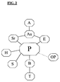
- the flow diagram of the emergency call device is shown in FIG.
- the device is with a battery (B) or similar replaceable power source.
- B battery
- N replaceable power source
- a processor in the device automatically dialed a defined emergency number (e.g. police).
- the connection is over a known cellular network, e.g. the GSM.
- the processor itself is coupled to a transmitter (Sr) and a receiver (E), which via an output unit (Au) are connected to the antenna (A).
- This is one Connection between the emergency caller and the emergency call center established.
- About the Hearing (H) and speech (S) on the emergency call device is a verbal communication possible.
- the emergency call device (N) with a location processor (OP) equipped with the well-known GPS (Global Positioning System) to determine the position of the device.
- the location processor (OP) determines the position of the device and sends it Data on the output unit (Au) and the antenna (A) to the emergency call center.
Landscapes
- Engineering & Computer Science (AREA)
- Business, Economics & Management (AREA)
- Emergency Management (AREA)
- Human Computer Interaction (AREA)
- Computer Networks & Wireless Communication (AREA)
- Signal Processing (AREA)
- Computer Security & Cryptography (AREA)
- Physics & Mathematics (AREA)
- General Physics & Mathematics (AREA)
- Alarm Systems (AREA)
Abstract
Der Erfindung liegt die Aufgabe zugrunde, ein einfaches und effektives
Notrufverfahren anzugeben, das einen Notruf durch Kommunikation zwischen
dem Notrufenden und der Notrufstelle ermöglicht. Durch Drücken einer Taste (T)
an einem Notrufgerät (N) wird intern eine Energiequelle aktiviert und selbsttätig
über an sich bekannte Mobilfunknetze eine Verbindung zu einer Notrufstelle
(z.B. Polizei) hergestellt. Nach dem Herstellen der Verbindung ist eine
Kommunikation zwischen den beiden Stellen möglich. Ist das Notrufgerät (N) mit
einem Ortungsprozessor ausgestattet, können die ermittelten Positionsdaten des
Gerätes an die Notrufstelle gesendet werden.
Description
Notrufsysteme und Verfahren sind an sich bekannt. Dabei gibt es
unterschiedliche Möglichkeiten der Übertragung des Notrufes von der
notrufenden Stelle bis hin zu der Steile, die diesen Notruf entgegennimmt und
weiter verarbeitet. Ist ein Notruf abgesetzt worden und sind entsprechende
Maßnahmen eingeleitet worden, kann man von einer geschlossenen Rettungskette
sprechen. Jedes Glied in dieser Kette hat eine fest umschriebene Funktion.
Ausgehend von diesem Stand der Technik hat sich die Erfindung die Aufgabe
gestellt, ein Notrufgerät vorzuschlagen, das es ermöglicht die Zeiten einer
Auslösung eines Notrufes in vielen Situationen erheblich zu verkürzen.
Grundsätzlich besteht das Problem, das an dem Ort, wo es zu einer
Gefahrensituation (z.B. ein Verbrechen) oder zu einem Unfall kommt, oft kein
Notruftelefon zur Verfügung steht. In diesen Fällen sind Personen in Ihrer Freizeit
oder bei Ihrer beruflichen Tätigkeit mit dem Problem konfrontiert so schnell wie
nur irgend möglich einen Notruf abzusetzen, damit die oben erwähnte
Rettungskette geschlossen und die damit verbundenen Maßnahmen in die Wege
geleitet werden können. Hinzu kommt, daß die Gefahrensituation oft eine Panik
bei dem Notrufenden auslöst, in der er die entsprechende Notrufnummer falsch
wählt oder sogar vergißt.
Um die Möglichkeit zu eröffnen, die Zeit zum Absetzen eines Notrufes zu
verkürzen, schlägt die Erfindung ein sogenanntes mobiles Notrufgerät vor, damit
zu fast jeder Zeit, an fast jedem Ort und in fast jeder Situation Notrufe abgesetzt
werden können.
Zusätzlich kann das Notrufgerät mit einer Einrichtung versehen sein, die es
ermöglicht die Position des Gerätes über das GPS (Global Positioning System) zu
ermitteln. Dies ist dann von Vorteil, wenn es dem Notrufenden in der
Gefahrensituation nicht möglich ist seine Position verbal der Notrufstelle
mitzuteilen.
Bei dem in Figur 1 dargestellten Gerät (N) handelt es sich um ein kleines,
leichtes, und handliches mit nur einer Taste (T) versehenes mobiles Notrufgerät,
das ohne zusätzliche Belastung fast überall mitgeführt werden kann.
Das Notrufgerät ist in seiner Art ähnlich einem Mobiltelefon ausgeführt. Es
verfügt über einen Gehäusekörper (N), einer Hör-(H) und Sprachmuschel (S),
einer Notruftaste (T) und einer Antenne (A).
Das Gerät selbst ist mit nur einer Taste (T) ausgestattet, um zu gewährleisten, das
der Notrufende auch in Paniksituationen ohne fehlerhaftes Bedienen und ohne
Zeitverzögerung das Notrufgerät benutzen kann. Dabei ist die Taste (T) durch
eine Abdeckplatte oder eine leicht zerstörbare Einrichtung gegen unbeabsichtigtes
Betätigen geschützt.
Wird die Abdeckplatte angehoben bzw. die leicht zerstörbare Einrichtung entfernt
und die Taste (N) gedrückt, wird im Notrufgerät selbst eine Stromversorgung
hergestellt und zwar in der Form, das durch das betätigen der Taste (T) die für
den Betrieb des Gerätes nötige Netzspannung aufgebaut wird.
Um zu verhindern das es zu einer vorzeitigen Entladung des Gerätes kommt ist
die Spannungsversorgung mit der Taste (T) gekoppelt. Da es sich um ein mobiles
Notrufgerät handelt, das nur im Gebrauchszustand, das heißt beim Absetzen eines
Notrufes funktionieren soll, wird eine Stromspannung erst bei der Benutzung
benötigt.
In Figur 2 ist das Ablaufschema des Notrufgerätes dargestellt. Das Gerät ist mit
einer Batterie (B) oder einer ähnlichen auswechselbaren Stromquelle versehen.
Somit ist auch nach längerer Nichtbenutzung ein Gebrauch des Gerätes (N)
gewährleistet, da kein Ruhestrom fließt.
Ist die Spannungsversorgung aufgebaut, wird über einen Prozessor im Gerät
selbsttätig eine definierte Notrufnummer (z.B. Polizei) gewählt. Die Verbindung
wird über ein bekanntes Mobilfunknetz, z.B. das GSM, aufgebaut. Der Prozessor
selbst ist mit einem Sender (Sr) und einem Empfänger (E) gekoppelt, die über
eine Ausgangseinheit (Au) mit der Antenne (A) verbunden sind. Dadurch ist eine
Verbindung zwischen dem Notrufenden und der Notrufstelle hergestellt. Über die
Hör (H)- und Sprachmuschel (S) am Notrufgerät ist eine verbale Kommunikation
möglich.
Gleichzeitig ist es denkbar, das Notrufgerät (N) mit einem Ortungsprozessor (OP)
auszustatten, dem es ermöglicht über das bekannte GPS (Global Positioning
System) die Position des Gerätes zu ermitteln. Nach dem Drücken der Taste (T)
ermittelt der Ortungsprozessor (OP) die Position des Gerätes und sendet die
Daten über die Ausgangseinheit (Au) und die Antenne (A) an die Notrufstelle.
Claims (10)
- Notrufverfahren, bei dem durch Drücken einer Taste (T) an einem Notrufgerät (N) intern eine Energiequelle aktiviert und automatisch über ein an sich schon bekanntes Mobilfunknetz der Kontakt zu einer Notrufstelle hergestellt wird. Nach dem Herstellen des Kontaktes ist eine Kommunikation in Form von Sprache zwischen dem Notrufenden und der Notrufstelle möglich.
- Notrufverfahren nach Anspruch 1,
dadurch gekennzeichnet, daß das Notrufgerät (N) mit nur einer Taste (T) ausgestattet ist. - Notrufverfahren nach Anspruch 1,
dadurch gekennzeichnet, daß das Notrufgerät (N) mit einer Batterie (B) oder einer anderen austauschbaren Energiequelle ausgerüstet ist. - Notrufverfahren nach Anspruch 1,
dadurch gekennzeichnet, daß die interne Energiequelle des Gerätes erst bei Betätigen der Taste (T) am Notrufgerät (N) aktiviert wird. - Notrufverfahren nach Anspruch 1,
dadurch gekennzeichnet, daß das Notrufgerät (N) über eine selbsttätige Wähleinrichtung verfügt. - Notrufverfahren nach Anspruch 1,
dadurch gekennzeichnet, daß das Notrufgerät (N) den Kontakt zur Notrufstelle über ein an sich bekanntes Mobilfunknetz herstellt. - Notrufverfahren nach Anspruch 1,
dadurch gekennzeichnet, daß das Notrufgerät (N) mit einer Sprech-(S) und Hörmuschel (H) ausgestattet ist, die eine Kommunikation zwischen dem Notrufenden und der Notrufstelle ermöglichen. - Notrufverfahren nach Anspruch 1,
dadurch gekennzeichnet, daß das Notrufgerät (N) als kleines, transportables Gerät ausgeführt ist. - Notrufverfahren nach Anspruch 1,
dadurch gekennzeichnet, das die Taste (T) am Notrufgerät (N) durch eine Abdeckplatte oder eine andere Schutzvorrichtung gegen unbeabsichtigtes Drücken gesichert ist. - Notrufgerät nach den Ansprüchen 1 bis 9,
dadurch gekennzeichnet, daß das Gerät (N) über einen an sich bekannten Ortungsprozessor (OP) verfügt, der die Position des Gerätes ermittelt und die Daten über eine Ausgangseinheit(Au) und die Antenne (A) an die Notrufstelle überträgt.
Priority Applications (1)
| Application Number | Priority Date | Filing Date | Title |
|---|---|---|---|
| EP98105494A EP0946037A1 (de) | 1998-03-26 | 1998-03-26 | Mobiles Notrufgerät |
Applications Claiming Priority (1)
| Application Number | Priority Date | Filing Date | Title |
|---|---|---|---|
| EP98105494A EP0946037A1 (de) | 1998-03-26 | 1998-03-26 | Mobiles Notrufgerät |
Publications (1)
| Publication Number | Publication Date |
|---|---|
| EP0946037A1 true EP0946037A1 (de) | 1999-09-29 |
Family
ID=8231648
Family Applications (1)
| Application Number | Title | Priority Date | Filing Date |
|---|---|---|---|
| EP98105494A Withdrawn EP0946037A1 (de) | 1998-03-26 | 1998-03-26 | Mobiles Notrufgerät |
Country Status (1)
| Country | Link |
|---|---|
| EP (1) | EP0946037A1 (de) |
Cited By (11)
| Publication number | Priority date | Publication date | Assignee | Title |
|---|---|---|---|---|
| JP2003529271A (ja) * | 2000-03-29 | 2003-09-30 | シキュア・アラート・インコーポレーテッド | 単一のボタン駆動による非常用電話 |
| WO2004021733A1 (en) * | 2002-08-30 | 2004-03-11 | Qualcomm Incorporated | Beacon for locating and tracking wireless terminals |
| FR2863429A1 (fr) * | 2003-12-03 | 2005-06-10 | Bernard Peyronny | Telephone portable pour personnes agees et/ou handicapees |
| EP1675367A1 (de) * | 2004-12-23 | 2006-06-28 | Owasys Advanced Wireless Devices, S.L.L. | Handy und Verfahren zum Aufbau eines Notanrufes |
| US7737841B2 (en) | 2006-07-14 | 2010-06-15 | Remotemdx | Alarm and alarm management system for remote tracking devices |
| US7804412B2 (en) | 2005-08-10 | 2010-09-28 | Securealert, Inc. | Remote tracking and communication device |
| US7936262B2 (en) | 2006-07-14 | 2011-05-03 | Securealert, Inc. | Remote tracking system with a dedicated monitoring center |
| US8232876B2 (en) | 2008-03-07 | 2012-07-31 | Securealert, Inc. | System and method for monitoring individuals using a beacon and intelligent remote tracking device |
| CN103209264A (zh) * | 2013-03-29 | 2013-07-17 | 苏州佳世达电通有限公司 | 移动装置的紧急求助方法及系统 |
| US8514070B2 (en) | 2010-04-07 | 2013-08-20 | Securealert, Inc. | Tracking device incorporating enhanced security mounting strap |
| US8797210B2 (en) | 2006-07-14 | 2014-08-05 | Securealert, Inc. | Remote tracking device and a system and method for two-way voice communication between the device and a monitoring center |
Citations (4)
| Publication number | Priority date | Publication date | Assignee | Title |
|---|---|---|---|---|
| US5365570A (en) * | 1992-06-02 | 1994-11-15 | Boubelik Mark J | Emergency cellular telephone apparatus |
| DE4413974A1 (de) * | 1994-04-21 | 1995-11-02 | Siemens Ag | Notrufsystem |
| US5563931A (en) * | 1994-08-16 | 1996-10-08 | Sos Wireless Communications & National Dispatch Center | Emergency wireless telephone and control system, and method |
| EP0809117A2 (de) * | 1996-05-23 | 1997-11-26 | Sun Microsystems, Inc. | Notruf-Positionsbestimmungsgerät mit Übertragung der Positionsdaten mittels drahtlosem Telephon |
-
1998
- 1998-03-26 EP EP98105494A patent/EP0946037A1/de not_active Withdrawn
Patent Citations (4)
| Publication number | Priority date | Publication date | Assignee | Title |
|---|---|---|---|---|
| US5365570A (en) * | 1992-06-02 | 1994-11-15 | Boubelik Mark J | Emergency cellular telephone apparatus |
| DE4413974A1 (de) * | 1994-04-21 | 1995-11-02 | Siemens Ag | Notrufsystem |
| US5563931A (en) * | 1994-08-16 | 1996-10-08 | Sos Wireless Communications & National Dispatch Center | Emergency wireless telephone and control system, and method |
| EP0809117A2 (de) * | 1996-05-23 | 1997-11-26 | Sun Microsystems, Inc. | Notruf-Positionsbestimmungsgerät mit Übertragung der Positionsdaten mittels drahtlosem Telephon |
Cited By (15)
| Publication number | Priority date | Publication date | Assignee | Title |
|---|---|---|---|---|
| JP2003529271A (ja) * | 2000-03-29 | 2003-09-30 | シキュア・アラート・インコーポレーテッド | 単一のボタン駆動による非常用電話 |
| EP1269641A4 (de) * | 2000-03-29 | 2005-05-04 | Secure Alert Inc | Durch eine einzige taste aktiviertes notruftelefon |
| WO2004021733A1 (en) * | 2002-08-30 | 2004-03-11 | Qualcomm Incorporated | Beacon for locating and tracking wireless terminals |
| FR2863429A1 (fr) * | 2003-12-03 | 2005-06-10 | Bernard Peyronny | Telephone portable pour personnes agees et/ou handicapees |
| EP1675367A1 (de) * | 2004-12-23 | 2006-06-28 | Owasys Advanced Wireless Devices, S.L.L. | Handy und Verfahren zum Aufbau eines Notanrufes |
| US7804412B2 (en) | 2005-08-10 | 2010-09-28 | Securealert, Inc. | Remote tracking and communication device |
| US8031077B2 (en) | 2005-08-10 | 2011-10-04 | Securealert, Inc. | Remote tracking and communication device |
| US7737841B2 (en) | 2006-07-14 | 2010-06-15 | Remotemdx | Alarm and alarm management system for remote tracking devices |
| US7936262B2 (en) | 2006-07-14 | 2011-05-03 | Securealert, Inc. | Remote tracking system with a dedicated monitoring center |
| US8013736B2 (en) | 2006-07-14 | 2011-09-06 | Securealert, Inc. | Alarm and alarm management system for remote tracking devices |
| US8797210B2 (en) | 2006-07-14 | 2014-08-05 | Securealert, Inc. | Remote tracking device and a system and method for two-way voice communication between the device and a monitoring center |
| US8232876B2 (en) | 2008-03-07 | 2012-07-31 | Securealert, Inc. | System and method for monitoring individuals using a beacon and intelligent remote tracking device |
| US8514070B2 (en) | 2010-04-07 | 2013-08-20 | Securealert, Inc. | Tracking device incorporating enhanced security mounting strap |
| US9129504B2 (en) | 2010-04-07 | 2015-09-08 | Securealert, Inc. | Tracking device incorporating cuff with cut resistant materials |
| CN103209264A (zh) * | 2013-03-29 | 2013-07-17 | 苏州佳世达电通有限公司 | 移动装置的紧急求助方法及系统 |
Similar Documents
| Publication | Publication Date | Title |
|---|---|---|
| DE69428931T2 (de) | Zellulartelefon | |
| DE19625581C2 (de) | Vorrichtung und Verfahren für ein Notfunktelefonsystem | |
| EP0979571A2 (de) | Mobilfunkgerät mit verringertem tastensatz | |
| DE602004001452T2 (de) | Telefonnachrichtennachsendeverfahren und Vorrichtung | |
| EP0889631A1 (de) | Mobiles Notruftelefon | |
| DE19706638C1 (de) | Verfahren und Einrichtung zur GPS-unterstützten Hilferufauslösung | |
| DE4407059A1 (de) | Mobiles Funktelephon | |
| EP0925700B1 (de) | Grossraumreisefahrzeug mit einer nachrichtentechnischen verbindungseinrichtung sowie verbindungseinrichtung und teilnehmerstation | |
| DE19507223C2 (de) | Notrufsystem | |
| DE3843870C2 (de) | Funknetz | |
| DE602004005998T2 (de) | Konfiguration eines tragbaren schlüssellosen telefons durch sms | |
| DE19859025C2 (de) | Funkgerät | |
| DE2640008C2 (de) | Verfahren zur Herstellung einer Funksprechverbindung bei einem Notruf in einem Funknetz | |
| DE102011086509A1 (de) | Vorrichtung für eine drahtlose, bidirektionale Sprachübertragung | |
| DE19516810A1 (de) | Vorrichtung zur Abgabe eines Notsignals an einen Notsignalempfänger | |
| DE3428355C2 (de) | ||
| DE10004041A1 (de) | Personen-Notruf-System und Verfahren zur Alarmübermittlung eines Personen-Notruf-Systems | |
| WO1999063770A2 (de) | Mobiltelefon zur abgabe eines notrufes | |
| DE19855826A1 (de) | Telekommunikationssystem und Sicherheitssystem für die Hilfe oder zur Rettung von Personen im In- und Ausland | |
| EP1505808A1 (de) | Mobiles Kommunikationsendgerät für Kinder | |
| DE29706223U1 (de) | Telefongerät | |
| DE19625367B4 (de) | Notrufsignalisierung in Bündelfunknetzen | |
| DE2203214C3 (de) | Anordnung für eine Fernsprechstation mit Wahlmöglichkeit bei aufgelegtem Handapparat | |
| DE29911588U1 (de) | Pkw-Verbandkasten mit integrierter Notrufanlage | |
| EP0989716A1 (de) | Verfahren und Vorrichtung zum Verzögern des Gesprächsbeginns zu Fernsprechendgeräten |
Legal Events
| Date | Code | Title | Description |
|---|---|---|---|
| PUAI | Public reference made under article 153(3) epc to a published international application that has entered the european phase |
Free format text: ORIGINAL CODE: 0009012 |
|
| AK | Designated contracting states |
Kind code of ref document: A1 Designated state(s): AT BE CH DE DK ES FI FR GB GR IE IT LI LU MC NL PT SE |
|
| AX | Request for extension of the european patent |
Free format text: AL;LT;LV;MK;RO;SI |
|
| AKX | Designation fees paid | ||
| REG | Reference to a national code |
Ref country code: DE Ref legal event code: 8566 |
|
| STAA | Information on the status of an ep patent application or granted ep patent |
Free format text: STATUS: THE APPLICATION IS DEEMED TO BE WITHDRAWN |
|
| 18D | Application deemed to be withdrawn |
Effective date: 20000330 |