EP0947617A2 - Méthode pour fabriquer un fil et métier à filer pour cela - Google Patents
Méthode pour fabriquer un fil et métier à filer pour cela Download PDFInfo
- Publication number
- EP0947617A2 EP0947617A2 EP99106080A EP99106080A EP0947617A2 EP 0947617 A2 EP0947617 A2 EP 0947617A2 EP 99106080 A EP99106080 A EP 99106080A EP 99106080 A EP99106080 A EP 99106080A EP 0947617 A2 EP0947617 A2 EP 0947617A2
- Authority
- EP
- European Patent Office
- Prior art keywords
- suction
- spinning
- spinning machine
- machine according
- thread
- Prior art date
- Legal status (The legal status is an assumption and is not a legal conclusion. Google has not performed a legal analysis and makes no representation as to the accuracy of the status listed.)
- Granted
Links
- 238000009987 spinning Methods 0.000 title claims description 46
- 238000000034 method Methods 0.000 title description 4
- 238000007378 ring spinning Methods 0.000 claims abstract description 16
- 239000000835 fiber Substances 0.000 claims description 69
- 230000006835 compression Effects 0.000 claims description 32
- 238000007906 compression Methods 0.000 claims description 32
- 238000004519 manufacturing process Methods 0.000 claims description 9
- 241000239290 Araneae Species 0.000 claims description 2
- 230000000694 effects Effects 0.000 description 6
- 238000005056 compaction Methods 0.000 description 5
- 235000021156 lunch Nutrition 0.000 description 4
- 229910000831 Steel Inorganic materials 0.000 description 3
- 230000002093 peripheral effect Effects 0.000 description 3
- 239000010959 steel Substances 0.000 description 3
- 229920000742 Cotton Polymers 0.000 description 2
- 238000003860 storage Methods 0.000 description 2
- 206010020112 Hirsutism Diseases 0.000 description 1
- 238000007664 blowing Methods 0.000 description 1
- 239000007795 chemical reaction product Substances 0.000 description 1
- 238000005253 cladding Methods 0.000 description 1
- 230000004048 modification Effects 0.000 description 1
- 238000012986 modification Methods 0.000 description 1
- 210000000056 organ Anatomy 0.000 description 1
- 238000005096 rolling process Methods 0.000 description 1
- 239000004753 textile Substances 0.000 description 1
- 238000004804 winding Methods 0.000 description 1
- 210000002268 wool Anatomy 0.000 description 1
Images



Classifications
-
- D—TEXTILES; PAPER
- D01—NATURAL OR MAN-MADE THREADS OR FIBRES; SPINNING
- D01H—SPINNING OR TWISTING
- D01H1/00—Spinning or twisting machines in which the product is wound-up continuously
- D01H1/02—Spinning or twisting machines in which the product is wound-up continuously ring type
- D01H1/025—Spinning or twisting machines in which the product is wound-up continuously ring type with a condensing device between drafting system and spinning unit
-
- D—TEXTILES; PAPER
- D01—NATURAL OR MAN-MADE THREADS OR FIBRES; SPINNING
- D01H—SPINNING OR TWISTING
- D01H5/00—Drafting machines or arrangements ; Threading of roving into drafting machine
- D01H5/18—Drafting machines or arrangements without fallers or like pinned bars
- D01H5/26—Drafting machines or arrangements without fallers or like pinned bars in which fibres are controlled by one or more endless aprons
-
- D—TEXTILES; PAPER
- D01—NATURAL OR MAN-MADE THREADS OR FIBRES; SPINNING
- D01H—SPINNING OR TWISTING
- D01H7/00—Spinning or twisting arrangements
- D01H7/02—Spinning or twisting arrangements for imparting permanent twist
- D01H7/04—Spindles
- D01H7/18—Arrangements on spindles for suppressing yarn balloons
Definitions
- the invention relates to a method for producing a yarn, in which a fiber sliver delivered by a drafting system first subjected to compression and then by means of a ring spinning device is rotated and wound as well a spinning machine by means of which such a method is carried out can be.
- Compaction devices in the form of with a perforation track provided, rotating, cylindrical rollers (DE 44 26 249 A1) or of circumferential, perforated Flexible straps (EP 0 635 590 A2) are known.
- the compression of a fiber sliver delivered by a drafting system offers the advantage that the fiber sliver is summarized closely can be fed to the twist zone in which it becomes a yarn is solidified. Jumps into this tightly summarized fiber sliver the rotation given to it by the rotation device to close to the clamping line, i.e. the spinning triangle is very small. This has the consequence that the loss of splitting edge fibers is minimal and that the yarn produced has little protruding fibers has, i.e. has little hairiness.
- String balloonless or thread balloon reduced spinning has the effect, among other things, that the thread tension in the thread piece between the pair of output rollers the drafting systems and spindle tip are reduced. Presumably it is this effect that the one with the compression of the The fiber fiber effect is effective and advantageous supported.
- the method according to the invention is accordingly based on stretched unconsolidated fiber sliver, compresses this fiber sliver and turns these compressed fiber lunches without a thread balloon or thread balloon reduced by means of spindle attachments on spinning spindles of ring spinning devices before using these ring spinning devices be wound up.
- a spinning machine for performing this method has a drafting system, at the exit of which a below Suction-suction device that conveys and compresses the sliver is arranged, which is a perforation track, i.e. one in Direction of the movement of the fiber sliver running row smaller Has suction openings to which the fibers of the fiber sliver are sucked become.
- the compression device is a ring spinning device downstream, whose spinning spindle with spindle attachments for thread balloonless or thread balloon reduced turning and winding of the yarn.
- the compaction devices can be rotating, rigid, hollow suction rolls, as suction rotors or as rotating, flexible Suction straps should be formed inside with suction stand.
- the spindle attachments can be used as spinning fingers or as Spinning crowns are formed.
- the device according to the invention also with devices for manufacturing by coregarn and / or false twine.
- the core thread In a core yarn, the core thread should be as complete as possible the outer fibers that determine the external appearance are embedded become. In normal core yarn spinning, this is done by that the core thread of the last, usually in the Main area of warp fed wide spread fiber sliver while the sheath fibers are wrapped around the core thread by rotating the fiber structure between the pair of output rollers and the organ giving the rotation, as a rule that is, a ring spinning spindle. This embedding takes place on some places along the yarn often incomplete what represents a loss in quality of the core yarn produced.
- the joint compression of the fiber sliver and the embedded in it Core thread in the sheath fibers in addition to screwing by compacting does a more effective, less Gaps and more uniform over the length of the yarn Covering the core thread with the sheath fibers.
- each fiber sliver is one Core thread comes in or several core threads come in and a core yarn is formed from it by twisting. It is however also possible, in particular two with at least one Core yarn doped fiber lunches run together before giving rotation and then only by giving rotation to produce a so-called false thread from two core yarns.
- a false thread is a textile thread, at to which two untwisted fibers are given rotation together.
- the two fibers are wrapped around each other and given the fiber structure thus formed rotation.
- Real thread this false twist differs in that the two Components do not have their own rotation, but only by the looping around by turning them together in the end product are kept similarly separate from one another real thread is the case.
- a false thread appears the more similar to a real thread, ever the two components remain more clearly recognizable in the false twine.
- the fibers that make up each of the consists of two fiber lunches combined into a compact fiber structure, which when merging is far less condensed with the respective other fiber structure.
- the the two fiber associations therefore remain more clearly separated and the false thread appears more like a real thread.
- a particularly effective embedding of the core thread is then achieved if this according to the invention before the compression zone fiber sliver still lying there is fed as centrally as possible becomes. This is particularly the case if the core thread is the Output roller pair of the drafting system fed on its inlet side becomes.
- the core thread can also be direct be fed to the compression zone.
- the core thread Drafting system fed from that side - from above or from below on which the strappy is arranged and around the Deflection edge on the inlet side of the apron.
- the apron is in the area of its inlet side assigned a guide roller around which the core thread is guided. If the compaction device has a suction roller, can the core thread can also be fed to the circumference of this suction roller.
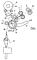
- the spinning machine according to the invention has a drafting system 1 which is more common Design with an input roller pair 2, a middle roller pair 3 and a pair of output rollers 4.
- the lower rollers 2 ', 3 'and 4' of these pairs of rollers are designed as steel rollers, which extend over the length of the drafting system area of the spinning machine extend and point in the area of work Corrugation on.
- the top rollers 2 '', 3 '' and 4 '' are twin top rollers trained who provided with elastic covering 5 and by means of a handlebar, not shown, on one indicated in FIG Carrying and loading arm 6 are mounted and spring-loaded.
- rollers 2 'and 2' 'of the middle roller pair 2 are with straps 7 equipped, each in not shown, also on Support and load arm 6 or on the punch of the drafting system stored strappy cages are guided.
- This drafting system 1 delivers a fully stretched but not yet twisted solidified fiber sliver 8. It is understood that the invention also realized in conjunction with other types of drafting systems can be.
- This drafting system 1 can have different compaction devices 10 for the fiber sliver 8 delivered by the drafting system be.
- FIGS. 1 to 3 there is the compression device 10 from an over the run of the fiber sliver 8, So above the drafting machine level lying suction roll 11.
- Suction roll 11 has a perforation 12 in the form of a Small round or transverse line arranged around its circumference elongated suction openings 13. It lies on two driven lower rollers 14 and 15, which like the lower rollers of drafting device 1 pass through the drafting device area.
- the suction roller 11 is cup-shaped and by means of ball bearings 17 together with their twin roller an axle 18 mounted in the support and load arm 6.
- This suction chamber 20 is connected via a pipe or hose 21 a suction source 24 including a motor 22 and a suction pump 23 connected.
- the suction chamber 20 limits the suction effect to one Compression zone 25 in which they are against the inner circumference the suction roller 11 opens. The acts in this compression zone 25 Suction on the outside of the suction roller 11.
- the jacket of the hollow suction roll 11 can be made of steel.
- elastic coverings 5 may be provided.
- the suction roll 11 which with the elastic Cover 5 is provided, in Fig. 2 it is the lower rollers 14 and 15.
- Fig. 4 shows an embodiment in which the suction roller 26, the similar to the suction roller 11 described in connection with FIG. 1 can be arranged under the run of the sliver 8 and is designed as a driven lower roller. At least it is you an upper roller 27 assigned, which as a rotation stop for the device issuing the rotation - here in form a ring spinning device - initiated rotation. At the beginning A further top roller 28 can be arranged in the compression zone 25 be.
- the top rollers 27, 28 are preferably twin rollers trained and with the top rollers 2 ", 3" and 4 "of Drafting unit 1 held in its support and loading arm 6 and charged.
- the suction roller 26 contains the by a shield 19th separate suction chamber 20 which delimits the compression zone 25.
- the Suction straps 29 also have the center described above Perforation 12 extending around its circumference in the form of a line small suction openings 13.
- the suction chamber 20 is arranged here its underside, which the strand of fiber facing 8 Suction strap is open, so that the suction through the Perforation 12 of the suction strap onto the fiber sliver can act.
- a suction strap wraps around 31, the suction strap 29 of FIG. 5 described above can correspond to a lower roller 32.
- This lower roller 32 is located on a continuous over the stretching field area of the spinning machine, driven, further lower roller 33.
- the from Suction strap 31 wrapped around the lower roller 32 is an upper roller 34 assigned.
- the lower roller wrapped by the suction strap 31 32 and the top roller 34 assigned to it are as twin rollers trained and held in a support and load arm 6 and pressurized.
- the top pressure roller 34 can be elastic covering 5 have or - since they on the suction strap 31 made of elastic Plastic rests - also have a steel jacket.
- the Suction strap 31 made of elastic plastic again has the perforation 12 in the form of suction openings arranged around its circumference 13 and also wraps around a connected to a suction source Suction chamber 20.
- the arrangement of a separate strappy twin bottom roller 32 is selected to the suction strap 31st easier to replace when worn.
- the compression device 10 can also according to FIGS. 7 and 8 a perforation 12 containing on its peripheral surface Have suction rotor 35.
- the suction rotor 35 is arranged so that the level of its perforation 12 approximately in one of the rollers 4 ', 4 '' of the output roller pair 4 tangent in their nip line Level lies. 8, the suction rotor 35 is in the plane of its perforation 12 cut. Contains the inside of the suction rotor 35 again a suction chamber 20 connected to the suction source 24, the suction line 21 runs through the hollow axis of the suction rotor.
- a pressure roller 36 At the periphery of the suction rotor 35 is at the end of the compression zone 25 a pressure roller 36 by means of a tension spring 37 pressed resiliently.
- the suction rotor 35 can by means of a its hollow shaft adjacent tangential belt 38 driven be.
- the lower rollers 2 ', 3' and 4 'of the drafting unit 1 and the driven ones Bottom rolls 14, 15; 26, 30 'and 33 of the respective compression devices 11 are by a dash-dotted in Fig. 1 Lines of action 39 symbolized gear in one another coordinated speed ratios driven.
- 5 6 and 9 and 10 have the lower rollers 15, 30 'and 31, from which the fiber sliver 8 in the area where she is given rotation, one Diameter on how it is generally used in drafting systems for the Processing of the respective staple fibers has proven to be expedient Has. For cotton, for example, this diameter is 27 mm to 32 mm.
- the respective compression device 10 is a common one Ring spinning device 40 with spinning spindle 41, spindle bench 42, Ring bank 43, spinning ring 44 and ring traveler 45 arranged downstream.
- the spinning spindle 41 with a spindle attachment in Shape of a spinning finger 46 or a spinning crown 47 (FIG. 7) fitted.
- the drafting system 1 delivers from the output roller pair 4 a fiber sliver 8, which due to the diameter of the incoming Roving and the warping has a certain width.
- This fiber sliver 8 is used in the embodiments of FIG. 1 supports the suction unit by means of the transport strap 16 11, 26, 29, 31 and 35 respectively.
- the fiber sliver 8 is subject to suction through the perforation 12 of these suction units. Through the suction, they are in the fiber sliver 8 lateral fibers on the narrow line of the perforation 12 sucked in and the fiber sliver thereby compressed. In this compacted state, it is sent to the ring spinning device 40 delivered and solidified by this by granting rotation and wound up.
- the spindle attachment catches spinning fingers 46 or spinning crown 47 in cooperation with the thread guide 48 den thread 49 coming in from the compression device 10, wraps it around the sleeve 50 and guides it without a thread balloon or with only a very small, reduced thread balloon to the ring traveler 45 to.
- the device according to the invention can also be equipped with a core yarn device 51 can be connected to produce core yarn.
- Core yarn is a yarn in which one is preferred core thread consisting of an endless, synthetic thread due to sheath fibers of finite length, usually cotton or / and Wool fibers, is covered.
- the drafting system 1 assigned to this purpose two rolling rollers 52 on which a core thread spool 54 containing a core thread 53 rests.
- One of the unwinding rollers 52 in the embodiment is the 5 the core thread 53 on the inlet side of the top roller 4 '' of the output roller pair 4 of the drafting system.
- the unrolling rollers 52 are at a peripheral speed of the pair of output rollers 4 driven peripheral speed, around the core thread 53 of the fiber sliver 8 with its withdrawal speed from the main draft zone between the pairs of rollers 3 and 4 to run at the appropriate speed.
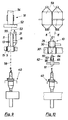
- a core yarn device 51 of FIG. 9 relates to the Embodiment of the compression device according to FIG. 2.
- the ability of the suction units containing the perforation 12 11, 26, 29, 31 and 35, the fiber sliver 8 or its fibers laterally suction is limited.
- the fiber sliver 8 is therefore not or only changes to a small extent. So that the core thread 53 the fiber sliver 8 always runs in the center, a core thread guide 55 may be provided, on the one hand the traversing movement of the core thread neutralized during the run from the core thread spool 54 and on the other hand the core thread for fiber sliver 8, i.e. to the Roving inlet funnel 56 of the drafting device 1 centered. This Position must be adjusted and when the fiber sliver shifts 8 be maintained.
- the core thread 53 accordingly runs into that at the beginning of the compression zone 25 still broad fiber sliver 8 and is there due to the cladding fibers that close together under the effect of suction the fiber sliver is encased tightly and opaque and for Core yarn 58.
- FIG. 10 - using the compression device as an example 10 of Fig. 5 - still shown the possibility that Setting up drafting device 1 for the production of false twine.
- the suction strap 29 has a perforation 12 in the form of two rows of suction openings 13 spaced apart from one another on.
- two are attached to the respective one Work the drafting system 1 of separate roving bobbins 59 incoming and stretched in the drafting system and through the Output roller pair 4 fiber sliver 8 delivered side by side, 8 'still compressed separately.
- This storage device 62 consists of a trap 63 with a pair of pins 64, between which the false thread 61 runs.
- the trap 63 sits on a support 65 with a narrow Stability range and is around this about an axis 66 tiltable. If one of the two components of the false twist 61 breaks, the remaining component moves laterally far that the trap 63 swung out of its stability range and tilts down. The remaining one Component wrapped around the pair of pins 64 and prevented rotation propagation also led to breakage.
Landscapes
- Engineering & Computer Science (AREA)
- Mechanical Engineering (AREA)
- Textile Engineering (AREA)
- Spinning Or Twisting Of Yarns (AREA)
Applications Claiming Priority (2)
| Application Number | Priority Date | Filing Date | Title |
|---|---|---|---|
| DE19815052 | 1998-04-03 | ||
| DE19815052A DE19815052B4 (de) | 1998-04-03 | 1998-04-03 | Verfahren zum Herstellen eines Garnes und Spinnmaschine hierfür |
Publications (4)
| Publication Number | Publication Date |
|---|---|
| EP0947617A2 true EP0947617A2 (fr) | 1999-10-06 |
| EP0947617A3 EP0947617A3 (fr) | 2000-01-19 |
| EP0947617B1 EP0947617B1 (fr) | 2002-10-23 |
| EP0947617B2 EP0947617B2 (fr) | 2007-01-24 |
Family
ID=7863541
Family Applications (1)
| Application Number | Title | Priority Date | Filing Date |
|---|---|---|---|
| EP99106080A Expired - Lifetime EP0947617B2 (fr) | 1998-04-03 | 1999-03-26 | Méthode pour fabriquer un fil et métier à filer pour cela |
Country Status (4)
| Country | Link |
|---|---|
| US (1) | US6189308B1 (fr) |
| EP (1) | EP0947617B2 (fr) |
| JP (1) | JPH11315423A (fr) |
| DE (2) | DE19815052B4 (fr) |
Cited By (1)
| Publication number | Priority date | Publication date | Assignee | Title |
|---|---|---|---|---|
| WO2004092461A1 (fr) * | 2003-04-17 | 2004-10-28 | Maschinenfabrik Rieter Ag | Dispositif de filage pourvu d'un dispositif de serrage d'un assemblage de fibres |
Families Citing this family (8)
| Publication number | Priority date | Publication date | Assignee | Title |
|---|---|---|---|---|
| DE10008610A1 (de) * | 2000-02-24 | 2001-08-30 | Zinser Textilmaschinen Gmbh | Streckwerk für eine Spinnereimaschine |
| JP2001279539A (ja) * | 2000-03-08 | 2001-10-10 | Zinser Textilmas Gmbh | 精紡機のドラフト機構 |
| DE10055300A1 (de) * | 2000-11-02 | 2002-05-08 | Stahlecker Fritz | Vorrichtung in einer Spinnmaschine zum Verdichten eines Faserverbandes |
| DE10127741C2 (de) * | 2001-06-08 | 2003-05-08 | Zinser Textilmaschinen Gmbh | Streckwerk für eine Spinnereimaschine |
| DE10145443A1 (de) * | 2001-09-14 | 2003-04-03 | Rieter Ag Maschf | Spinnmaschine mit Verdichtungseinrichtung |
| CH704137A1 (de) * | 2010-11-26 | 2012-05-31 | Rieter Ag Maschf | Vorrichtung zum Verdichten eines Faserverbandes an einer Spinnmaschine sowie Spinnmaschine. |
| CN102644134B (zh) * | 2012-05-22 | 2014-10-29 | 江南大学 | 一种四罗拉超大牵伸紧密纺装置 |
| CN102797078B (zh) * | 2012-09-07 | 2015-02-18 | 江苏鹿港科技股份有限公司 | 一种手指锭紧密纺针织绒的制备方法 |
Citations (2)
| Publication number | Priority date | Publication date | Assignee | Title |
|---|---|---|---|---|
| EP0635590A2 (fr) | 1993-07-14 | 1995-01-25 | Itv -Institut Für Textil-Und Verfahrenstechnik | Dispositif d'étirage à double manchon |
| DE4426249A1 (de) | 1994-07-25 | 1996-02-01 | Rieter Ag Maschf | Spinnverfahren und Spinnmaschine mit abgedeckter Saugwalze am Streckwerk |
Family Cites Families (9)
| Publication number | Priority date | Publication date | Assignee | Title |
|---|---|---|---|---|
| DE882066C (de) * | 1947-11-01 | 1953-07-06 | Warner Swasey Co | Streckwerk |
| FR1490473A (fr) * | 1965-10-12 | 1967-08-04 | Dispositif pour la condensation de fibres textiles | |
| DE4139067C2 (de) * | 1991-11-28 | 1993-11-25 | Skf Textilmasch Komponenten | Doppelriemchenstreckwerk für Spinnereimaschinen |
| DE19514408C5 (de) * | 1994-06-23 | 2007-08-16 | Maschinenfabrik Rieter Ag | Ringspinnverfahren |
| DE19526958C2 (de) * | 1995-07-24 | 1997-08-14 | Zinser Textilmaschinen Gmbh | Verfahren und Vorrichtung zum Entfernen und Zurückversetzen von fadenballonunterdrückenden Spindelaufsätzen |
| EP0893519B1 (fr) * | 1997-07-17 | 2002-11-06 | Zinser Textilmaschinen GmbH | Condenseur de mèche dans un dispositif d'étirage d'une machine de filature |
| DE19756393C2 (de) * | 1997-12-18 | 2001-08-16 | Zinser Textilmaschinen Gmbh | Spinnereimaschinen-Streckwerk |
| DE19815518C2 (de) * | 1998-03-30 | 2003-06-18 | Zinser Textilmaschinen Gmbh | Verfahren und Vorrichtung zum Spinnen mit unterdrücktem Fadenballon |
| DE19815051A1 (de) * | 1998-04-03 | 1999-10-14 | Zinser Textilmaschinen Gmbh | Spinnmaschine mit einem einen Saugrotor aufweisenden Streckwerk |
-
1998
- 1998-04-03 DE DE19815052A patent/DE19815052B4/de not_active Expired - Fee Related
-
1999
- 1999-03-25 JP JP11082295A patent/JPH11315423A/ja active Pending
- 1999-03-26 EP EP99106080A patent/EP0947617B2/fr not_active Expired - Lifetime
- 1999-03-26 DE DE59903137T patent/DE59903137D1/de not_active Expired - Fee Related
- 1999-04-02 US US09/285,585 patent/US6189308B1/en not_active Expired - Fee Related
Patent Citations (2)
| Publication number | Priority date | Publication date | Assignee | Title |
|---|---|---|---|---|
| EP0635590A2 (fr) | 1993-07-14 | 1995-01-25 | Itv -Institut Für Textil-Und Verfahrenstechnik | Dispositif d'étirage à double manchon |
| DE4426249A1 (de) | 1994-07-25 | 1996-02-01 | Rieter Ag Maschf | Spinnverfahren und Spinnmaschine mit abgedeckter Saugwalze am Streckwerk |
Cited By (1)
| Publication number | Priority date | Publication date | Assignee | Title |
|---|---|---|---|---|
| WO2004092461A1 (fr) * | 2003-04-17 | 2004-10-28 | Maschinenfabrik Rieter Ag | Dispositif de filage pourvu d'un dispositif de serrage d'un assemblage de fibres |
Also Published As
| Publication number | Publication date |
|---|---|
| EP0947617B1 (fr) | 2002-10-23 |
| EP0947617A3 (fr) | 2000-01-19 |
| US6189308B1 (en) | 2001-02-20 |
| DE19815052B4 (de) | 2005-12-15 |
| DE19815052A1 (de) | 1999-10-14 |
| DE59903137D1 (de) | 2002-11-28 |
| JPH11315423A (ja) | 1999-11-16 |
| EP0947617B2 (fr) | 2007-01-24 |
Similar Documents
| Publication | Publication Date | Title |
|---|---|---|
| EP0986659B1 (fr) | Procede et metier a filer destines a la production de fils a ame | |
| DE4323472C2 (de) | Doppelriemchen-Streckwerk | |
| EP0947614B1 (fr) | Métier de filature avec un dispositif d'étirage pourvu d'un cylindre d'aspiration | |
| EP0947615B1 (fr) | Procédé et métier de filature pour la production d'un fil fictif | |
| EP0947616A2 (fr) | Métier de filature avec un dispositif d'étirage pourvu d'un rotor d'aspiration | |
| EP0131170A1 (fr) | Procédé et dispositif de filature par fausse-torsion | |
| DE10236450A1 (de) | Spinnmaschine mit einem Mehrstufen-Verdichtungs-Streckwerk | |
| EP0947617B1 (fr) | Méthode pour fabriquer un fil et métier à filer pour cela | |
| EP1302572B1 (fr) | Métier à filer pour la réalisation de files comportant une âme | |
| DE19815049B4 (de) | Verfahren zum Herstellen eines Garnes und Spinnmaschine hierfür | |
| EP3842578B1 (fr) | Métier à filer à anneaux et procédé de fabrication d'un fil à âme | |
| DE2645119C3 (de) | Verfahren zur Herstellung eines Coregaras | |
| EP0887448B1 (fr) | Procédé et appareil pour la fabrication d'un fil textile | |
| EP2980284B1 (fr) | Procede de fabrication d'un fil produit par jet d'air | |
| EP3464691B1 (fr) | Élément de formation de fil pour une machine de pré-filage et machine de pré-filage équipée de cet élément | |
| DE19619307B4 (de) | Spinnmaschine mit einem am Ausgang eine Saugwalze aufweisenden Mehrstufen-Streckwerk sowie Verfahren zur Herstellung eines Spinnzwirnes und danach hergestellter Spinnzwirn | |
| DE102005009731A1 (de) | Flyerloses Spinnverfahren sowie Vorrichtung mit einem Streckwerk | |
| DE29824429U1 (de) | Spinnmaschine zum Herstellen von Coregarn | |
| DE2407357A1 (de) | Garn und verfahren zu seiner herstellung | |
| DE9422313U1 (de) | Doppelriemchen-Streckwerk | |
| AT385284B (de) | Vorrichtung zum herstellen eines garnes | |
| DE3610111A1 (de) | Verfahren und vorrichtung zum erzeugen von vorlagespulen fuer eine zwirnvorrichtung | |
| DE10063729A1 (de) | Spinnvorrichtung | |
| DE10022747A1 (de) | Spinnmaschine mit einer Vielzahl von Spinnstellen |
Legal Events
| Date | Code | Title | Description |
|---|---|---|---|
| PUAI | Public reference made under article 153(3) epc to a published international application that has entered the european phase |
Free format text: ORIGINAL CODE: 0009012 |
|
| AK | Designated contracting states |
Kind code of ref document: A2 Designated state(s): CH DE ES FR IT LI |
|
| AX | Request for extension of the european patent |
Free format text: AL;LT;LV;MK;RO;SI |
|
| PUAL | Search report despatched |
Free format text: ORIGINAL CODE: 0009013 |
|
| AK | Designated contracting states |
Kind code of ref document: A3 Designated state(s): AT BE CH CY DE DK ES FI FR GB GR IE IT LI LU MC NL PT SE |
|
| AX | Request for extension of the european patent |
Free format text: AL;LT;LV;MK;RO;SI |
|
| 17P | Request for examination filed |
Effective date: 20000202 |
|
| AKX | Designation fees paid |
Free format text: CH DE ES FR IT LI |
|
| GRAG | Despatch of communication of intention to grant |
Free format text: ORIGINAL CODE: EPIDOS AGRA |
|
| GRAG | Despatch of communication of intention to grant |
Free format text: ORIGINAL CODE: EPIDOS AGRA |
|
| GRAH | Despatch of communication of intention to grant a patent |
Free format text: ORIGINAL CODE: EPIDOS IGRA |
|
| 17Q | First examination report despatched |
Effective date: 20020423 |
|
| GRAH | Despatch of communication of intention to grant a patent |
Free format text: ORIGINAL CODE: EPIDOS IGRA |
|
| GRAA | (expected) grant |
Free format text: ORIGINAL CODE: 0009210 |
|
| AK | Designated contracting states |
Kind code of ref document: B1 Designated state(s): CH DE ES FR IT LI |
|
| PG25 | Lapsed in a contracting state [announced via postgrant information from national office to epo] |
Ref country code: FR Free format text: LAPSE BECAUSE OF FAILURE TO SUBMIT A TRANSLATION OF THE DESCRIPTION OR TO PAY THE FEE WITHIN THE PRESCRIBED TIME-LIMIT Effective date: 20021023 |
|
| REG | Reference to a national code |
Ref country code: CH Ref legal event code: EP |
|
| REF | Corresponds to: |
Ref document number: 59903137 Country of ref document: DE Date of ref document: 20021128 |
|
| PG25 | Lapsed in a contracting state [announced via postgrant information from national office to epo] |
Ref country code: ES Free format text: LAPSE BECAUSE OF FAILURE TO SUBMIT A TRANSLATION OF THE DESCRIPTION OR TO PAY THE FEE WITHIN THE PRESCRIBED TIME-LIMIT Effective date: 20030429 |
|
| PLBI | Opposition filed |
Free format text: ORIGINAL CODE: 0009260 |
|
| EN | Fr: translation not filed | ||
| PLAX | Notice of opposition and request to file observation + time limit sent |
Free format text: ORIGINAL CODE: EPIDOSNOBS2 |
|
| 26 | Opposition filed |
Opponent name: MASCHINENFABRIK RIETER AG Effective date: 20030723 |
|
| PLBB | Reply of patent proprietor to notice(s) of opposition received |
Free format text: ORIGINAL CODE: EPIDOSNOBS3 |
|
| RAP2 | Party data changed (patent owner data changed or rights of a patent transferred) |
Owner name: SAURER GMBH & CO. KG |
|
| PLAY | Examination report in opposition despatched + time limit |
Free format text: ORIGINAL CODE: EPIDOSNORE2 |
|
| PLAY | Examination report in opposition despatched + time limit |
Free format text: ORIGINAL CODE: EPIDOSNORE2 |
|
| PLBC | Reply to examination report in opposition received |
Free format text: ORIGINAL CODE: EPIDOSNORE3 |
|
| RDAF | Communication despatched that patent is revoked |
Free format text: ORIGINAL CODE: EPIDOSNREV1 |
|
| APAH | Appeal reference modified |
Free format text: ORIGINAL CODE: EPIDOSCREFNO |
|
| APBP | Date of receipt of notice of appeal recorded |
Free format text: ORIGINAL CODE: EPIDOSNNOA2O |
|
| PLAB | Opposition data, opponent's data or that of the opponent's representative modified |
Free format text: ORIGINAL CODE: 0009299OPPO |
|
| PGFP | Annual fee paid to national office [announced via postgrant information from national office to epo] |
Ref country code: IT Payment date: 20060331 Year of fee payment: 8 |
|
| APBQ | Date of receipt of statement of grounds of appeal recorded |
Free format text: ORIGINAL CODE: EPIDOSNNOA3O |
|
| D26 | Opposition filed (deleted) | ||
| APBU | Appeal procedure closed |
Free format text: ORIGINAL CODE: EPIDOSNNOA9O |
|
| PLAZ | Examination of admissibility of opposition: despatch of communication + time limit |
Free format text: ORIGINAL CODE: EPIDOSNOPE2 |
|
| PLBA | Examination of admissibility of opposition: reply received |
Free format text: ORIGINAL CODE: EPIDOSNOPE4 |
|
| PLBP | Opposition withdrawn |
Free format text: ORIGINAL CODE: 0009264 |
|
| PUAH | Patent maintained in amended form |
Free format text: ORIGINAL CODE: 0009272 |
|
| STAA | Information on the status of an ep patent application or granted ep patent |
Free format text: STATUS: PATENT MAINTAINED AS AMENDED |
|
| 27A | Patent maintained in amended form |
Effective date: 20070124 |
|
| AK | Designated contracting states |
Kind code of ref document: B2 Designated state(s): CH DE ES FR IT LI |
|
| REG | Reference to a national code |
Ref country code: CH Ref legal event code: AEN Free format text: AUFRECHTERHALTUNG DES PATENTES IN GEAENDERTER FORM |
|
| REG | Reference to a national code |
Ref country code: ES Ref legal event code: FD2A Effective date: 20030327 |
|
| EN | Fr: translation not filed | ||
| PGFP | Annual fee paid to national office [announced via postgrant information from national office to epo] |
Ref country code: CH Payment date: 20090326 Year of fee payment: 11 |
|
| PGFP | Annual fee paid to national office [announced via postgrant information from national office to epo] |
Ref country code: DE Payment date: 20090330 Year of fee payment: 11 |
|
| PG25 | Lapsed in a contracting state [announced via postgrant information from national office to epo] |
Ref country code: IT Free format text: LAPSE BECAUSE OF NON-PAYMENT OF DUE FEES Effective date: 20070326 |
|
| REG | Reference to a national code |
Ref country code: CH Ref legal event code: PL |
|
| PG25 | Lapsed in a contracting state [announced via postgrant information from national office to epo] |
Ref country code: LI Free format text: LAPSE BECAUSE OF NON-PAYMENT OF DUE FEES Effective date: 20100331 Ref country code: DE Free format text: LAPSE BECAUSE OF NON-PAYMENT OF DUE FEES Effective date: 20101001 Ref country code: CH Free format text: LAPSE BECAUSE OF NON-PAYMENT OF DUE FEES Effective date: 20100331 |