EP0947639B1 - Verfahren zur Herstellung einer Deckenkonstruktion sowie modulares Gewölbesystem zur Durchführung des Verfahrens - Google Patents
Verfahren zur Herstellung einer Deckenkonstruktion sowie modulares Gewölbesystem zur Durchführung des Verfahrens Download PDFInfo
- Publication number
- EP0947639B1 EP0947639B1 EP99103197A EP99103197A EP0947639B1 EP 0947639 B1 EP0947639 B1 EP 0947639B1 EP 99103197 A EP99103197 A EP 99103197A EP 99103197 A EP99103197 A EP 99103197A EP 0947639 B1 EP0947639 B1 EP 0947639B1
- Authority
- EP
- European Patent Office
- Prior art keywords
- vault
- accordance
- modules
- shell
- vaulted structure
- Prior art date
- Legal status (The legal status is an assumption and is not a legal conclusion. Google has not performed a legal analysis and makes no representation as to the accuracy of the status listed.)
- Expired - Lifetime
Links
- 238000000034 method Methods 0.000 title claims description 30
- 239000004567 concrete Substances 0.000 claims abstract description 32
- 239000004566 building material Substances 0.000 claims abstract description 17
- 229910000831 Steel Inorganic materials 0.000 claims abstract description 14
- 239000010959 steel Substances 0.000 claims abstract description 14
- 238000001746 injection moulding Methods 0.000 claims abstract description 5
- 239000004033 plastic Substances 0.000 claims abstract description 5
- 229920003023 plastic Polymers 0.000 claims abstract description 5
- 230000002787 reinforcement Effects 0.000 claims description 34
- 239000011150 reinforced concrete Substances 0.000 claims description 12
- 238000010276 construction Methods 0.000 claims description 11
- 238000004519 manufacturing process Methods 0.000 claims description 10
- 238000009826 distribution Methods 0.000 claims description 9
- 239000011210 fiber-reinforced concrete Substances 0.000 claims description 8
- 230000003014 reinforcing effect Effects 0.000 claims description 5
- 239000011521 glass Substances 0.000 claims description 4
- 238000009435 building construction Methods 0.000 claims description 2
- 239000004035 construction material Substances 0.000 claims 7
- 239000000835 fiber Substances 0.000 abstract description 8
- 239000011449 brick Substances 0.000 description 6
- 238000009415 formwork Methods 0.000 description 6
- 239000000243 solution Substances 0.000 description 3
- 238000009436 residential construction Methods 0.000 description 2
- 239000007787 solid Substances 0.000 description 2
- 239000004568 cement Substances 0.000 description 1
- 239000002131 composite material Substances 0.000 description 1
- 238000007596 consolidation process Methods 0.000 description 1
- 239000006260 foam Substances 0.000 description 1
- 230000005484 gravity Effects 0.000 description 1
- 229910052602 gypsum Inorganic materials 0.000 description 1
- 239000010440 gypsum Substances 0.000 description 1
- 238000005338 heat storage Methods 0.000 description 1
- 230000008595 infiltration Effects 0.000 description 1
- 238000001764 infiltration Methods 0.000 description 1
- 239000007924 injection Substances 0.000 description 1
- 238000002347 injection Methods 0.000 description 1
- 238000009417 prefabrication Methods 0.000 description 1
- 239000004576 sand Substances 0.000 description 1
- 238000005507 spraying Methods 0.000 description 1
- 239000012899 standard injection Substances 0.000 description 1
- 230000003068 static effect Effects 0.000 description 1
Images


Classifications
-
- E—FIXED CONSTRUCTIONS
- E04—BUILDING
- E04B—GENERAL BUILDING CONSTRUCTIONS; WALLS, e.g. PARTITIONS; ROOFS; FLOORS; CEILINGS; INSULATION OR OTHER PROTECTION OF BUILDINGS
- E04B7/00—Roofs; Roof construction with regard to insulation
- E04B7/08—Vaulted roofs
- E04B7/10—Shell structures, e.g. of hyperbolic-parabolic shape; Grid-like formations acting as shell structures; Folded structures
- E04B7/102—Shell structures
-
- E—FIXED CONSTRUCTIONS
- E04—BUILDING
- E04B—GENERAL BUILDING CONSTRUCTIONS; WALLS, e.g. PARTITIONS; ROOFS; FLOORS; CEILINGS; INSULATION OR OTHER PROTECTION OF BUILDINGS
- E04B5/00—Floors; Floor construction with regard to insulation; Connections specially adapted therefor
- E04B5/16—Load-carrying floor structures wholly or partly cast or similarly formed in situ
- E04B5/32—Floor structures wholly cast in situ with or without form units or reinforcements
- E04B5/36—Floor structures wholly cast in situ with or without form units or reinforcements with form units as part of the floor
Definitions
- the invention relates to a method the specified in the preamble of claim 1 kind to produce a covering Building construction such as in particular a ceiling construction. It affects also a modular vault system that in the preamble of claim 18 specified type to carry out the procedure. On such a method and such a vault system are e.g. known from FR-A-2 515 233.
- the usual ceiling constructions are usually based on one Reinforced concrete floor.
- Such a reinforced concrete ceiling has a high one Load capacity.
- one disadvantage is their relatively high steel content as well as their high weight.
- FR 2 515 233 is already a vault made of shell-like vault modules known that both as lost formwork as can also serve as a carrier for absorbing load forces.
- the Modules are provided with integral pillars.
- a vault known from BE-A-698 444 consists of reinforced concrete modules, the steel reinforcement provided in the form of a steel mesh is.
- a floor which consists of several cross-vaulted plates is made of gypsum or gravel concrete with a steel mesh are reinforced.
- the aim of the invention is to provide a method of the type mentioned create with the most simple and inexpensive way possible their respective design variable and in particular also lighter covers or ceiling structures with high load-bearing capacity are producible. Furthermore, one should be suitable for carrying out the method inexpensive modular vault system can be created.
- the method according to the invention is in particular at One or two family houses, but also in multi-family houses and / or in connection with special spatially arched structural solutions applicable to public buildings and / or the like.
- the variably configurable decorative vaulted structure achieved a relatively high load-bearing capacity is, so that less steel reinforcements are required or in certain Applications even completely dispensed with such steel reinforcements can be. Above all, the reinforcement no longer has to be nationwide his.
- DE-A-26 58 622 is already a formwork element remaining in the building known from fiber concrete, for example the shape of a Shell or a trough. This publication contains however, no reference to the use of such a formwork element to create a vaulted structure.
- US-A-4 697 954 discloses a walk-in base for a landfill described for which a variety of bowl-like or vaulted, e.g. prefabricated parts made of reinforced concrete is used. By moving Seams of finished parts are at least about each supported a pillar on a foundation. The shell or vault-like shape of the prefabricated parts is used to discharge in the landfill emerging infiltration.
- One formed by vaulted modules load-bearing vault structure in the sense of the invention is not present here.
- the vault modules are preferably injection molded manufactured.
- the vaulted structure is preferred only provide such reinforcements in some areas. These reinforcements can then, for example, depending on the respective static system introduced into the troughs formed on the top of the vault structure become.
- the vaulted structure can be at least partially one or more multi-axis curved, each by at least one vault module formed shell are generated. So it is possible, for example, the vaulted structure at least partially by at least one two or to produce a three-axis curved shell. So not only are barrel vaults, but also, for example, cross ridges and / or the like conceivable.
- the respective arches can, for example, at least partially through a semicircular, segmental or ogival cross-section be formed. For example, it is multi-part such as in particular four-part shells for the production of cross-ridge vaults or of three-axis shaped so-called Bohemian cap vaults possible.
- cassette elements that are curved in two axes can also be used can be used for barrel vaults.
- the use of fan-shaped arch segments for dome vaults conceivable.
- Another example is complex combinations multi-part such as four-part structures for canopy-like vaults called.
- the procedure is based on at least one vault column and / or at least one wall abutment-supported shells with a Provide additional latch support before the respective building material filling is applied.
- the shells or the vault modules can be at least partially over belt straps they are connected to one another and / or supported become.
- At least one shell from several vault modules is put together. All shells are preferred several parts. In a preferred practical embodiment, a each shell composed of four vault modules.
- Another advantageous embodiment of the method according to the invention is characterized in that the vault modules at least partially screwed together and their joints are at least partially filled with fiber concrete, with respective ones Reinforcements can be incorporated.
- a continuous, preferably an upper reinforcement layer formed by fiber concrete is applied become.
- a lightweight concrete can be used as the building material filling.
- the vault modules or shells of the vault structure poured from the top with the lightweight concrete.
- the vaulted structure one at least essentially just replenishing the Troughs and the distribution of the vertical load on the supporting arch structure serving light building material filling applied.
- Light building material can be filled with, for example, a lightweight, lightweight concrete be used.
- the vault structure is used one of both the filling of the troughs and the load distribution as well as the reinforcement of the vault supporting lightweight concrete layer applied. It may be necessary in the whole filling Reinforcements are included. A special one, before the reinforcing layer applied as a rule is here not required, which simplifies the overall production.
- the procedure is carried out by the vault modules or the shells vault structure formed as lost formwork for a heavy concrete ceiling used, in this case on the vault structure before again a continuous, preferably formed by fiber concrete upper Reinforcement layer is applied.
- any combination of the different variants is also possible conceivable. It is, for example, in the area of housing construction possible to design a basement ceiling for higher loads, for what expediently both on the vault structure of the filling the troughs and the load distribution as well as the reinforcement of the vault serving supporting lightweight concrete layer is applied while for the ground floor ceiling usually an at least essentially only the Filling the troughs and light building material filling for load distribution is sufficient.
- the invention Modular vault system is in claim 18 specified.
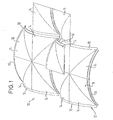
- Figure 1 shows a schematic, perspective partial representation of one of the Manufacture of a ceiling structure 10 serving vault structure 12.
- the vault structure 12 is made using several prefabricated ones Partial shell-like vault modules 14 produced according to the modular system.
- Partial shell-like vault modules 14 produced according to the modular system.
- Figure 1 are two each in the manner of a cross ridge vault Biaxially curved shells 16 can be seen, each consisting of four butted assembled vault modules 14 are assembled.
- One of the four vault modules 14 forming the front shell 16 is for the better Representation of this module led upwards.
- On the right side of the two shells 16 two further vault modules 14 can be seen.
- the shells 16 and the vault modules 14 are at least partially connected and supported by means of belt bows formed on them.
- FIG 2 shows a schematic plan view of one of several multi-part Shell 16 composite vault structure 12. There are six to recognize such shells 16 in two mutually parallel rows are arranged with three shells each. Each of these shells 16 is again composed of four vault modules 14 each. The bowls 16 are connected to each other via webbing 18. The through the multi-part Vault structure 12 produced by shells 16 is locally, for example, in the Area supported by vaulted columns. Two such bases are in of Figure 2 identified by a reference numeral 20.
- the vault modules 14 can for example be made of plastic, glass and / or steel taser concrete, preferably using the injection molding process are made.
- Foam body or brick elements based on the basic shape be built up, even lighter and more statically resilient, cassette-like domed structures are produced. So even with a certain Formal restriction of vaulted brick ceilings possible.
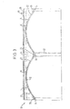
- Figure 3 shows a schematic, partially sectioned side view Embodiment of a ceiling structure 10, in which the on the top the vault structure 12 formed troughs 22 with at least one essentially only serving to fill up these troughs 22 Building material filling 24 were filled.
- Corresponding connecting strips 26 can be seen in FIG.
- tongue and groove connections are also fundamental and / or the like conceivable.
- the light building material filling 24 subsequently applied extends to Top edge 28 of the bare ceiling.
- the upper edge of the bottom is marked with the reference number 30 marked.
- a pore-weight lightweight concrete can be used, which in particular Liapor balls with some sand and cement for consolidation may contain.
- the assembled from the prefabricated vault modules 14 Shells 16 of the arch structure 12 are in particular on Arch columns 32 and abutments 34 supported. At least during the application of the building material filling 24, the shells 16 can also be provided with an additional latch support.
- the vault modules 14 and the shells 16 can, for example, the have the shape shown in Figures 1 and 2. Basically is however also the use of differently designed vault modules 14 or Bowls 16 possible.
- the vaulted structure 12 is only provided with reinforcements in some areas, which in the present case were specifically introduced into the troughs 22 and are contained, for example, in the connecting strip 26.
- the Reinforcements are expediently targeted in the area of supports to accommodate the side lift and / or at local weak points of the Vault structure 12 used.
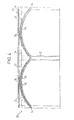
- FIG. 4 differs from that of Figure 3 essentially in that the local connecting strips 26 (see FIG. 3) and instead before applying the light building material filling 24 a continuous, preferably by fiber concrete formed upper reinforcement layer 36 on the arch structure 12 is applied. With this full-surface reinforcement layer 36 reached an even higher load capacity of the ceiling structure 10.
- the light building material filling 24 serves as well as that shown in FIG. 3 Embodiment at least essentially only the replenishment the troughs 22 and the distribution of the vertical load on the load-bearing vault structure 12. In the rest, this also has in FIG. 4 shown embodiment at least substantially the same structure as in FIG. 3, parts corresponding to one another having the same reference numerals assigned.
- Figure 5 shows an embodiment of a ceiling construction in which the Shells 16 as in the embodiment according to FIG Connection points such as in the area of belt bends again are connected to one another via connecting strips 26.
- This in the Figure 5 illustrated embodiment differs from that of the figure 3, however, that on the vaulted structure 12 one of both the filling the troughs 22 and the load distribution as well as the reinforcement of the vault-supporting lightweight concrete layer 38 was applied.
- a lightweight concrete of the "LB 15" type can be used become.
- this embodiment has at least essentially the same structure as that of Figure 3, corresponding to each other Parts are assigned the same reference numerals again.
- the present embodiment has i.a.
- FIG. 6 shows a schematic, partially sectioned side view of a another embodiment of a ceiling construction, in its manufacture the vault structure 16 as lost formwork for a heavy concrete ceiling 40 is used, which is a serious in the present case Reinforced concrete ceiling.
- a continuous, preferably through Fiber reinforced concrete formed upper reinforcement layer 36 applied.
- the top edge of the bare ceiling is the same as in the previous exemplary embodiments again by the reference number 28 and the upper edge of the floor is again identified by reference number 30.
- the vaulted structure 12 is also open again in the present case Arch columns 32 and abutments 34 supported.
- the bowls 16 the vault structure 12 are again by prefabricated vault modules 14 formed.
- FIGS. 3 to 6 can in particular can also be combined in the area of residential construction. That's the way it is For example, it makes sense to design a basement ceiling for higher loads, for which the embodiment according to FIG. 5 appears to be the most suitable.
- the lighter versions can be used for the ground floor ceiling 3 and 4 are sufficient.
- the standard injection molding process made of plastic, glass and / or Vault modules 14 made of steel fiber concrete can for example a normal size of 1.8 mx 1.8 m with a shell thickness of about 3 own up to 6 cm.
- the curvature height of the from the vault modules 14 Shells 16 formed can, for example, be between approximately 20 cm and approximately 200 cm and are, for example, about 70 cm.
- the prefabricated Vault modules 14 can, for example, have a length of approximately 1 m to own more than 5 m. In principle, however, other dimensions are also conceivable.
- the vault modules 14 can be on the top in the center of gravity be provided with eyelets and / or the like, what their Handling during assembly of the vaulted structure 12 is simplified.
Landscapes
- Engineering & Computer Science (AREA)
- Architecture (AREA)
- Physics & Mathematics (AREA)
- Electromagnetism (AREA)
- Civil Engineering (AREA)
- Structural Engineering (AREA)
- Lining And Supports For Tunnels (AREA)
- Forms Removed On Construction Sites Or Auxiliary Members Thereof (AREA)
- Separation By Low-Temperature Treatments (AREA)
- Automatic Assembly (AREA)
- Air Bags (AREA)
Description
- Figur 1
- eine schematische, perspektivische Teildarstellung einer der Herstellung einer Deckenkonstruktion dienenden Gewölbestruktur,
- Figur 2
- eine schematische Draufsicht einer aus mehreren mehrteiligen Schalen zusammengesetzten Gewölbestruktur,
- Figur 3
- eine schematische, teilweise geschnittene Seitenansicht einer Ausführungsform einer Deckenkonstruktion mit einer zumindest im wesentlichen nur der Auffüllung der Mulden dienenden leichten Baustoffüllung,
- Figur 4
- eine schematische, teilweise geschnittene Seitenansicht einer weiteren Ausführungsform einer Deckenkonstruktion mit einer zumindest im wesentlichen nur der Auffüllung der Mulden dienenden leichten Baustoffüllung und einer zusätzlichen auf die Gewölbestruktur aufgebrachten Verstärkungsschicht,
- Figur 5
- eine schematische, teilweise geschnittene Seitenansicht einer weiteren Ausführungsform einer Deckenkonstruktion mit einer sowohl der Lastverteilung als auch der Verstärkung des Gewölbes dienenden tragenden Leichtbetonschicht und
- Figur 6
- eine schematische, teilweise geschnittene Seitenansicht einer weiteren Ausführungsform einer Deckenkonstruktion, bei deren Herstellung eine Gewölbestruktur als verlorene Schalung für eine schwere Betondecke dient.
- 10
- Deckenkonstruktion
- 12
- Gewölbestruktur
- 14
- Gewölbemodule
- 16
- Schalen
- 18
- Gurtbögen
- 20
- Stützstellen
- 22
- Mulden
- 24
- leichte Baustoffüllung
- 26
- Verbindungsstreifen
- 28
- Oberkante der Rohdecke
- 30
- Oberkante des Bodens
- 32
- Gewölbesäulen
- 34
- Wandwiderlager
- 36
- Verstärkungsschicht
- 38
- tragende Leichtbetonschicht
- 40
- schwere Betondecke
Claims (23)
- Verfahren zur Herstellung einer abdeckenden Baukonstruktion wie insbesondere einer Deckenkonstruktion (10), bei dem unter Verwendung vorzugsweise mehrerer vorgefertigter schalen- und/oder teilschalenartiger Gewölbemodule (14) nach dem Baukastensystem eine tragende Gewölbestruktur (12) erzeugt wird und die auf der Oberseite der Gewölbestruktur (12) gebildeten Mulden (22) bei den in ihrer Lage fixierten Gewölbemodulen (14) mit einer Baustofffüllung (24, 38, 40) aufgefüllt werden,
dadurch gekennzeichnet, dass die tragende Gewölbestruktur (12) unter Verwendung von Gewölbemodulen (14) aus Kunststoff-, Glas- und/oder Stahlfaserbeton erzeugt wird, wobei die Verbindungsstellen der Gewölbemodule (14) zumindest teilweise mit Faserbeton vergossen werden und als Baustofffüllung (24, 38, 40) ein Leichtbeton verwendet und die Gewölbemodule (14) bzw. Schalen (16) der Gewölbestruktur (12) von der Oberseite her mit dem Leichtbeton vergossen werden. - Verfahren nach Anspruch 1,
dadurch gekennzeichnet, dass die Gewölbemodule (14) im Spritzgussverfahren hergestellt werden. - Verfahren nach Anspruch 1 oder 2,
dadurch gekennzeichnet, dass die Gewölbestruktur (12) lediglich bereichsweise mit Bewehrungen versehen wird, wobei diese Bewehrungen vorzugsweise in die Mulden (22) eingebracht werden. - Verfahren nach Anspruch 3,
dadurch gekennzeichnet, dass die Bewehrungen zumindest teilweise gezielt im Bereich von Auflagern zur Aufnahme des Seitenhubs und/oder an lokalen Schwachstellen der Gewölbestruktur (12) eingesetzt werden. - Verfahren nach einem der vorhergehenden Ansprüche,
dadurch gekennzeichnet, dass die Gewölbestruktur (12) zumindest teilweise durch wenigstens eine ein- oder mehrachsig gekrümmte, jeweils durch wenigstens ein Gewölbemodul (14) gebildete Schale (16) erzeugt wird. - Verfahren nach Anspruch 5,
dadurch gekennzeichnet, dass die Gewölbestruktur (12) zumindest teilweise durch wenigstens eine zwei- oder dreiachsig gekrümmte Schale (16) erzeugt wird. - Verfahren nach einem der vorhergehenden Ansprüche,
dadurch gekennzeichnet, dass die auf wenigstens einer Gewölbesäule (32) und/oder wenigstens einem Wandwiderlager (34) abgestützten Schalen (16) mit einer zusätzlichen Riegelunterstützung versehen werden, bevor die Baustoffüllung (24, 38, 40) aufgebracht wird. - Verfahren nach einem der vorhergehenden Ansprüche,
dadurch gekennzeichnet, dass die Schalen (16) bzw. die Gewölbemodule (14) zumindest teilweise über an ihnen ausgebildete Gurtbögen (18) miteinander verbunden und/oder abgestützt werden. - Verfahren nach einem der vorhergehenden Ansprüche,
dadurch gekennzeichnet, dass wenigstens eine Schale (16) aus mehreren Gewölbemodulen (14) zusammengesetzt wird. - Verfahren nach Anspruch 9,
dadurch gekennzeichnet, dass wenigstens eine Schale (16) aus vier Gewölbemodulen (14) zusammengesetzt wird. - Verfahren nach einem der vorhergehenden Ansprüche,
dadurch gekennzeichnet, dass die Gewölbemodule (14) zumindest teilweise miteinander verschraubt werden. - Verfahren nach einem der vorhergehenden Ansprüche,
dadurch gekennzeichnet, dass beim Vergießen der Verbindungsstellen der Gewölbemodule (14) mit Faserbeton auch jeweilige Bewehrungen mit eingearbeitet werden. - Verfahren nach einem der vorhergehenden Ansprüche,
dadurch gekennzeichnet, dass auf die Gewölbestruktur (12) eine durchgehende, vorzugsweise durch Faserbeton gebildete obere Verstärkungsschicht (36) aufgebracht wird, bevor die Mulden (22) mit der Baustoffüllung (24, 40) aufgefüllt werden. - Verfahren nach einem der vorhergehenden Ansprüche,
dadurch gekennzeichnet, dass auf die Gewölbestruktur (12) eine zumindest im wesentlichen nur der Auffüllung der Mulden (22) und der Verteilung der vertikalen Belastung auf die tragende Gewölbestruktur (12) dienende leichte Baustoffüllung (24) aufgebracht wird. - Verfahren nach Anspruch 14,
dadurch gekennzeichnet, dass als leichte Baustoffüllung (24) ein haufwerksporiger Leichtbeton verwendet wird. - Verfahren nach einem der vorhergehenden Ansprüche,
dadurch gekennzeichnet, dass auf die Gewölbestruktur (12) eine sowohl der Auffüllung der Mulden und der Lastverteilung als auch der Verstärkung des Gewölbes dienende tragende Leichtbetonschicht (38) aufgebracht wird. - Verfahren nach einem der vorhergehenden Ansprüche,
dadurch gekennzeichnet, dass auf die Gewölbestruktur (12) eine durchgehende, vorzugsweise durch Faserbeton gebildete obere Verstärkungsschicht (36) aufgebracht wird und dass die durch die Gewölbemodule (14) bzw. die Schalen (16) gebildete Gewölbestruktur (12) als verlorene Schalung für eine schwere Betondecke (40) verwendet wird. - Modulares Gewölbesystem mit mehreren vorgefertigten schalenund/oder teilschalenartigen Gewölbemodulen (14), die nach dem Baukastensystem zu einer tragenden Gewölbestruktur (12) zusammensetzbar sind, auf deren Oberseite Mulden (22) gebildet sind, die anschließend mit einer Baustofffüllung (24, 38, 40) auffüllbar sind, zur Durchführung des Verfahrens nach einem der vorhergehenden Ansprüche,
dadurch gekennzeichnet, dass die Gewölbemodule (14) aus Kunststoff-, Glas- und/oder Stahlfaserbeton bestehen, wobei die Verbindungsstellen der Gewölbemodule (14) zumindest teilweise mit Faserbeton vergossen sind und als Baustofffüllung (24, 38, 40) ein Leichtbeton vorgesehen ist und die Gewölbemodule (14) bzw. Schalen (16) der Gewölbestruktur (12) von der Oberseite her mit dem Leichtbeton vergossen werden können. - Modulares Gewölbesystem nach Anspruch 18,
dadurch gekennzeichnet, dass die Gewölbemodule (14) im Spritzgußverfahren hergestellt sind. - Modulares Gewölbesystem nach Anspruch 18 oder 19,
dadurch gekennzeichnet, dass die aus den Gewölbemodulen (14) zusammengesetzte Gewölbestruktur (12) zumindest teilweise wenigstens eine ein- oder mehrachsig, vorzugsweise zwei- oder dreiachsig gekrümmte Schale (16) bildet. - Modulares Gewölbesystem nach einem der vorhergehenden Ansprüche,
dadurch gekennzeichnet, dass die Gewölbemodule (14) zumindest teilweise mit Gurtbögen (18) versehen sind, über die die Gewölbemodule (14) bzw. die durch diese gebildeten Schalen (16) miteinander verbindbar und/oder abstützbar sind. - Modulares Gewölbesystem nach einem der vorhergehenden Ansprüche,
dadurch gekennzeichnet, dass wenigstens eine Schale (16) aus mehreren Gewölbemodulen (14) zusammengesetzt ist. - Modulares Gewölbesystem nach Anspruch 22,
dadurch gekennzeichnet, dass wenigstens eine Schale (16) aus vier Gewölbemodulen (14) zusammengesetzt ist.
Applications Claiming Priority (2)
| Application Number | Priority Date | Filing Date | Title |
|---|---|---|---|
| DE19815100A DE19815100A1 (de) | 1998-04-03 | 1998-04-03 | Verfahren zur Herstellung einer Deckenkonstruktion sowie modulares Gewölbesystem zur Durchführung des Verfahrens |
| DE19815100 | 1998-04-03 |
Publications (2)
| Publication Number | Publication Date |
|---|---|
| EP0947639A1 EP0947639A1 (de) | 1999-10-06 |
| EP0947639B1 true EP0947639B1 (de) | 2004-10-13 |
Family
ID=7863573
Family Applications (1)
| Application Number | Title | Priority Date | Filing Date |
|---|---|---|---|
| EP99103197A Expired - Lifetime EP0947639B1 (de) | 1998-04-03 | 1999-02-18 | Verfahren zur Herstellung einer Deckenkonstruktion sowie modulares Gewölbesystem zur Durchführung des Verfahrens |
Country Status (4)
| Country | Link |
|---|---|
| EP (1) | EP0947639B1 (de) |
| AT (1) | ATE279604T1 (de) |
| DE (2) | DE19815100A1 (de) |
| ES (1) | ES2227916T3 (de) |
Families Citing this family (8)
| Publication number | Priority date | Publication date | Assignee | Title |
|---|---|---|---|---|
| AT510664B1 (de) * | 2010-10-20 | 2012-09-15 | Technologiezentrum Ski Und Alpinsport Gmbh | Bauwerk mit mindestens einem gekrümmten konstruktionselement aus beton sowie ein verfahren zur erstellung eines derartigen bauwerks |
| DE102012016044A1 (de) * | 2012-08-14 | 2014-02-20 | Jacek Synowietz | Eine selbsttragende, gebogene / gewölbte Deckenplatte ohne Unterkonstruktion aus Stahlbeton/ Holz/ Naturfasern/ Kunststoff / Metal mit Möglichkeit der Anordnung weitere Elemente wie: Vorspannung / zusätzliche Platten/ Randverstärkung. |
| CN106869390B (zh) * | 2017-04-07 | 2019-03-29 | 东南大学 | 一种张弦式的双曲拱形屋面板梁结构 |
| BE1027197B1 (nl) | 2019-04-18 | 2020-11-19 | Nick Vermeersch | Prefab boogelement voor booggewelven |
| EP3725970B1 (de) | 2019-04-18 | 2023-07-19 | Vermeersch, Nick | Vorgefertigtes bogenelement für bogengewölbe |
| CN111734032B (zh) * | 2020-06-23 | 2021-09-03 | 湖南城市学院 | 一种具有双曲拱壳的无梁楼盖结构及其施工方法 |
| CN111734033A (zh) * | 2020-06-23 | 2020-10-02 | 湖南城市学院 | 一种具有预制双曲拱壳的楼盖结构及其施工方法 |
| CN112064852A (zh) * | 2020-06-23 | 2020-12-11 | 湖南城市学院 | 一种具有双曲拱壳的楼盖结构及其施工方法 |
Citations (1)
| Publication number | Priority date | Publication date | Assignee | Title |
|---|---|---|---|---|
| US4697954A (en) * | 1984-12-11 | 1987-10-06 | Karl Grund | Basemented floor structure for a waste dump |
Family Cites Families (6)
| Publication number | Priority date | Publication date | Assignee | Title |
|---|---|---|---|---|
| FR742022A (de) * | 1933-02-24 | |||
| FR488430A (fr) * | 1917-02-03 | 1918-10-08 | Karl Pauli Billner | Nouveau système de construction de planchers en béton armé |
| DE1008471B (de) * | 1953-07-04 | 1957-05-16 | Holzmann Philipp Ag | Schalendach in Stahlbeton |
| FR1442994A (fr) * | 1965-08-13 | 1966-06-17 | Plaque unitaire préfabriquée en béton armé, notamment pour la construction de planchers | |
| DE2658622A1 (de) * | 1976-12-23 | 1978-06-29 | Heinz Carl | Schalungselement |
| FR2515233A1 (fr) * | 1981-10-23 | 1983-04-29 | Dumon Charles | Element modulaire pour la prefabrication de voutes |
-
1998
- 1998-04-03 DE DE19815100A patent/DE19815100A1/de not_active Withdrawn
-
1999
- 1999-02-18 EP EP99103197A patent/EP0947639B1/de not_active Expired - Lifetime
- 1999-02-18 DE DE1999510790 patent/DE59910790D1/de not_active Expired - Lifetime
- 1999-02-18 ES ES99103197T patent/ES2227916T3/es not_active Expired - Lifetime
- 1999-02-18 AT AT99103197T patent/ATE279604T1/de not_active IP Right Cessation
Patent Citations (1)
| Publication number | Priority date | Publication date | Assignee | Title |
|---|---|---|---|---|
| US4697954A (en) * | 1984-12-11 | 1987-10-06 | Karl Grund | Basemented floor structure for a waste dump |
Also Published As
| Publication number | Publication date |
|---|---|
| EP0947639A1 (de) | 1999-10-06 |
| ES2227916T3 (es) | 2005-04-01 |
| ATE279604T1 (de) | 2004-10-15 |
| DE59910790D1 (de) | 2004-11-18 |
| DE19815100A1 (de) | 1999-10-07 |
Similar Documents
| Publication | Publication Date | Title |
|---|---|---|
| EP0123642B1 (de) | Verbundträger | |
| DE2135007A1 (de) | Konstruktionselement | |
| EP0947639B1 (de) | Verfahren zur Herstellung einer Deckenkonstruktion sowie modulares Gewölbesystem zur Durchführung des Verfahrens | |
| DE2835849A1 (de) | Waerme- und schallisolierende verlorene schalung | |
| EP2024580A1 (de) | Flächige beton-tragkonstruktion sowie verfahren zur herstellung derselben | |
| DE2936986C2 (de) | ||
| DE69721311T2 (de) | Hausbaumodul und dazugehörige methode | |
| WO2013026566A1 (de) | Konstruktionsteile und bauteile aus faserverstärktem basaltgestein | |
| DE4421839C1 (de) | Schalungstafel aus Beton | |
| DE2649936C2 (de) | Behälter aus Stahlbeton und Verfahren zur Errichtung desselben | |
| EP0479816A1 (de) | Formstein. | |
| DE69816665T2 (de) | Schubverbinder für sandwichmauern aus beton und isolationsmaterial | |
| DE2629870A1 (de) | Konstruktionselemente und verfahren zu ihrer herstellung | |
| EP1725717B1 (de) | Verfahren zur erstellung eines tragfähigen mauerwerks sowie steine für die durchführung des verfahrens | |
| DE2022965A1 (de) | Stahlbetonaufbau | |
| DE2246441A1 (de) | Gebaeudekonstruktion | |
| AT372733B (de) | Bauwerksskelett aus lasttragenden vorgefertigten bauelementen | |
| DE3045663A1 (de) | Deckenelement | |
| DE2510061C3 (de) | Tragendes Stahlbeton-Fertigteil mit Feuchtigkeitsisolierung und Verfahren zu dessen Herstellung | |
| EP0159382A1 (de) | Bauwerk, insbesondere (Flüssigkeits-)Grossbehälter | |
| DE202025107892U1 (de) | Schnellmontagehalle | |
| DE19502174A1 (de) | Verbund-Träger | |
| DE2904442A1 (de) | Stahlbeton-deckenkonstruktion | |
| DE3424430A1 (de) | Kombinationssystem aus vorgefertigten bausegmenten fuer die errichtung vollstaendiges wandsaetzes eines gebaeudes | |
| DE3936050A1 (de) | Lamellierte stahlbetontragkonstruktion, verfahren zu deren verwirklichung, sowie stahlbetonfertigteil, schalungsbank und verfahren zur herstellung von stahlbetonfertigteilen, z. b. kassettenfoermigen fertigteilen mit zwillingsplatten |
Legal Events
| Date | Code | Title | Description |
|---|---|---|---|
| PUAI | Public reference made under article 153(3) epc to a published international application that has entered the european phase |
Free format text: ORIGINAL CODE: 0009012 |
|
| AK | Designated contracting states |
Kind code of ref document: A1 Designated state(s): AT BE CH CY DE DK ES FI FR GB GR IE IT LI LU MC NL PT SE |
|
| AX | Request for extension of the european patent |
Free format text: AL;LT;LV;MK;RO;SI |
|
| AKX | Designation fees paid | ||
| 17P | Request for examination filed |
Effective date: 20000329 |
|
| RBV | Designated contracting states (corrected) |
Designated state(s): AT CH DE ES FR IT LI NL |
|
| REG | Reference to a national code |
Ref country code: DE Ref legal event code: 8566 |
|
| 17Q | First examination report despatched |
Effective date: 20020624 |
|
| GRAP | Despatch of communication of intention to grant a patent |
Free format text: ORIGINAL CODE: EPIDOSNIGR1 |
|
| GRAS | Grant fee paid |
Free format text: ORIGINAL CODE: EPIDOSNIGR3 |
|
| GRAA | (expected) grant |
Free format text: ORIGINAL CODE: 0009210 |
|
| AK | Designated contracting states |
Kind code of ref document: B1 Designated state(s): AT CH DE ES FR IT LI NL |
|
| REG | Reference to a national code |
Ref country code: CH Ref legal event code: EP |
|
| REF | Corresponds to: |
Ref document number: 59910790 Country of ref document: DE Date of ref document: 20041118 Kind code of ref document: P |
|
| PGFP | Annual fee paid to national office [announced via postgrant information from national office to epo] |
Ref country code: NL Payment date: 20050211 Year of fee payment: 7 |
|
| PGFP | Annual fee paid to national office [announced via postgrant information from national office to epo] |
Ref country code: ES Payment date: 20050218 Year of fee payment: 7 |
|
| REG | Reference to a national code |
Ref country code: ES Ref legal event code: FG2A Ref document number: 2227916 Country of ref document: ES Kind code of ref document: T3 |
|
| ET | Fr: translation filed | ||
| PLBE | No opposition filed within time limit |
Free format text: ORIGINAL CODE: 0009261 |
|
| STAA | Information on the status of an ep patent application or granted ep patent |
Free format text: STATUS: NO OPPOSITION FILED WITHIN TIME LIMIT |
|
| 26N | No opposition filed |
Effective date: 20050714 |
|
| PG25 | Lapsed in a contracting state [announced via postgrant information from national office to epo] |
Ref country code: ES Free format text: LAPSE BECAUSE OF NON-PAYMENT OF DUE FEES Effective date: 20060220 |
|
| PG25 | Lapsed in a contracting state [announced via postgrant information from national office to epo] |
Ref country code: NL Free format text: LAPSE BECAUSE OF NON-PAYMENT OF DUE FEES Effective date: 20060901 |
|
| NLV4 | Nl: lapsed or anulled due to non-payment of the annual fee |
Effective date: 20060901 |
|
| PGFP | Annual fee paid to national office [announced via postgrant information from national office to epo] |
Ref country code: CH Payment date: 20070214 Year of fee payment: 9 |
|
| REG | Reference to a national code |
Ref country code: ES Ref legal event code: FD2A Effective date: 20060220 |
|
| PGFP | Annual fee paid to national office [announced via postgrant information from national office to epo] |
Ref country code: IT Payment date: 20070614 Year of fee payment: 9 |
|
| PGFP | Annual fee paid to national office [announced via postgrant information from national office to epo] |
Ref country code: FR Payment date: 20070212 Year of fee payment: 9 |
|
| REG | Reference to a national code |
Ref country code: CH Ref legal event code: PL |
|
| PG25 | Lapsed in a contracting state [announced via postgrant information from national office to epo] |
Ref country code: LI Free format text: LAPSE BECAUSE OF NON-PAYMENT OF DUE FEES Effective date: 20080229 Ref country code: CH Free format text: LAPSE BECAUSE OF NON-PAYMENT OF DUE FEES Effective date: 20080229 |
|
| REG | Reference to a national code |
Ref country code: FR Ref legal event code: ST Effective date: 20081031 |
|
| PG25 | Lapsed in a contracting state [announced via postgrant information from national office to epo] |
Ref country code: FR Free format text: LAPSE BECAUSE OF NON-PAYMENT OF DUE FEES Effective date: 20080229 |
|
| PG25 | Lapsed in a contracting state [announced via postgrant information from national office to epo] |
Ref country code: IT Free format text: LAPSE BECAUSE OF NON-PAYMENT OF DUE FEES Effective date: 20080218 |
|
| PGFP | Annual fee paid to national office [announced via postgrant information from national office to epo] |
Ref country code: AT Payment date: 20090515 Year of fee payment: 11 |
|
| PG25 | Lapsed in a contracting state [announced via postgrant information from national office to epo] |
Ref country code: AT Free format text: LAPSE BECAUSE OF NON-PAYMENT OF DUE FEES Effective date: 20100218 |
|
| PGFP | Annual fee paid to national office [announced via postgrant information from national office to epo] |
Ref country code: DE Payment date: 20160429 Year of fee payment: 18 |
|
| REG | Reference to a national code |
Ref country code: DE Ref legal event code: R119 Ref document number: 59910790 Country of ref document: DE |
|
| PG25 | Lapsed in a contracting state [announced via postgrant information from national office to epo] |
Ref country code: DE Free format text: LAPSE BECAUSE OF NON-PAYMENT OF DUE FEES Effective date: 20170901 |