EP0947657A2 - Gehäuse zur Befestigung von Stellantrieben zur Betätigung von Fenstern - Google Patents
Gehäuse zur Befestigung von Stellantrieben zur Betätigung von Fenstern Download PDFInfo
- Publication number
- EP0947657A2 EP0947657A2 EP99106303A EP99106303A EP0947657A2 EP 0947657 A2 EP0947657 A2 EP 0947657A2 EP 99106303 A EP99106303 A EP 99106303A EP 99106303 A EP99106303 A EP 99106303A EP 0947657 A2 EP0947657 A2 EP 0947657A2
- Authority
- EP
- European Patent Office
- Prior art keywords
- profile
- actuator
- housing according
- housing
- window
- Prior art date
- Legal status (The legal status is an assumption and is not a legal conclusion. Google has not performed a legal analysis and makes no representation as to the accuracy of the status listed.)
- Granted
Links
- 238000005553 drilling Methods 0.000 claims description 2
- 238000009434 installation Methods 0.000 description 6
- 230000007246 mechanism Effects 0.000 description 4
- 230000006978 adaptation Effects 0.000 description 1
- 238000004140 cleaning Methods 0.000 description 1
- 238000010276 construction Methods 0.000 description 1
- 238000005520 cutting process Methods 0.000 description 1
- 238000001125 extrusion Methods 0.000 description 1
- 210000003746 feather Anatomy 0.000 description 1
- 238000002347 injection Methods 0.000 description 1
- 239000007924 injection Substances 0.000 description 1
- 238000012423 maintenance Methods 0.000 description 1
- 238000004519 manufacturing process Methods 0.000 description 1
- 238000010422 painting Methods 0.000 description 1
- 238000004091 panning Methods 0.000 description 1
- 230000008439 repair process Effects 0.000 description 1
- 238000009420 retrofitting Methods 0.000 description 1
- 238000009423 ventilation Methods 0.000 description 1
Images


Classifications
-
- E—FIXED CONSTRUCTIONS
- E05—LOCKS; KEYS; WINDOW OR DOOR FITTINGS; SAFES
- E05F—DEVICES FOR MOVING WINGS INTO OPEN OR CLOSED POSITION; CHECKS FOR WINGS; WING FITTINGS NOT OTHERWISE PROVIDED FOR, CONCERNED WITH THE FUNCTIONING OF THE WING
- E05F15/00—Power-operated mechanisms for wings
- E05F15/60—Power-operated mechanisms for wings using electrical actuators
- E05F15/603—Power-operated mechanisms for wings using electrical actuators using rotary electromotors
- E05F15/611—Power-operated mechanisms for wings using electrical actuators using rotary electromotors for swinging wings
- E05F15/616—Power-operated mechanisms for wings using electrical actuators using rotary electromotors for swinging wings operated by push-pull mechanisms
- E05F15/619—Power-operated mechanisms for wings using electrical actuators using rotary electromotors for swinging wings operated by push-pull mechanisms using flexible or rigid rack-and-pinion arrangements
-
- E—FIXED CONSTRUCTIONS
- E05—LOCKS; KEYS; WINDOW OR DOOR FITTINGS; SAFES
- E05Y—INDEXING SCHEME ASSOCIATED WITH SUBCLASSES E05D AND E05F, RELATING TO CONSTRUCTION ELEMENTS, ELECTRIC CONTROL, POWER SUPPLY, POWER SIGNAL OR TRANSMISSION, USER INTERFACES, MOUNTING OR COUPLING, DETAILS, ACCESSORIES, AUXILIARY OPERATIONS NOT OTHERWISE PROVIDED FOR, APPLICATION THEREOF
- E05Y2201/00—Constructional elements; Accessories therefor
- E05Y2201/60—Suspension or transmission members; Accessories therefor
- E05Y2201/622—Suspension or transmission members elements
- E05Y2201/644—Flexible elongated pulling elements
- E05Y2201/656—Chains
-
- E—FIXED CONSTRUCTIONS
- E05—LOCKS; KEYS; WINDOW OR DOOR FITTINGS; SAFES
- E05Y—INDEXING SCHEME ASSOCIATED WITH SUBCLASSES E05D AND E05F, RELATING TO CONSTRUCTION ELEMENTS, ELECTRIC CONTROL, POWER SUPPLY, POWER SIGNAL OR TRANSMISSION, USER INTERFACES, MOUNTING OR COUPLING, DETAILS, ACCESSORIES, AUXILIARY OPERATIONS NOT OTHERWISE PROVIDED FOR, APPLICATION THEREOF
- E05Y2201/00—Constructional elements; Accessories therefor
- E05Y2201/60—Suspension or transmission members; Accessories therefor
- E05Y2201/622—Suspension or transmission members elements
- E05Y2201/71—Toothed gearing
- E05Y2201/722—Racks
- E05Y2201/724—Flexible
-
- E—FIXED CONSTRUCTIONS
- E05—LOCKS; KEYS; WINDOW OR DOOR FITTINGS; SAFES
- E05Y—INDEXING SCHEME ASSOCIATED WITH SUBCLASSES E05D AND E05F, RELATING TO CONSTRUCTION ELEMENTS, ELECTRIC CONTROL, POWER SUPPLY, POWER SIGNAL OR TRANSMISSION, USER INTERFACES, MOUNTING OR COUPLING, DETAILS, ACCESSORIES, AUXILIARY OPERATIONS NOT OTHERWISE PROVIDED FOR, APPLICATION THEREOF
- E05Y2900/00—Application of doors, windows, wings or fittings thereof
- E05Y2900/10—Application of doors, windows, wings or fittings thereof for buildings or parts thereof
- E05Y2900/13—Type of wing
- E05Y2900/148—Windows
Definitions
- the invention relates to a housing for fastening Actuators on windows, especially for the Operation of turn-tilt windows and a window with at least one actuator in a housing.
- Actuators for remote control of the rotary and Tilting movements of a window are, for example from the applicant's utility model application DE 29706637 U1 known.
- the one shown in this document inward opening turn-tilt window is typical of the Storey building, for both business and residential purposes.
- the windows are common because of the construction operationally safe both tilting the wing in a ventilation position, usually a horizontal one Rotation axis tilted in the lower area, as well Swiveling in a cleaning position allowed in which Windows can be cleaned from the inside.
- the panning the window is about a vertical axis along the side profile. To move one The other axis must first be released. This is done by locking and unlocking mechanisms, which are attached to the window sash.
- the one for actuation the locking and unlocking mechanisms provided Actuators are within the window profiles intended. The assembly of the actuators must therefore even before the windows are made in the profiles of the window.
- Another montage is from the German one Utility model DE 29622922 U1 known. There they are Actuators on the outside of the window frame or Window sash mounted. This makes the engine lighter accessible, for example during repairs or Maintenance is an advantage. It is also basically a subsequent installation of such actuators possible.
- the object of the invention is to provide a housing for To describe actuators that are as universal as possible can be used with different window profiles can, a reduced variety of types of actuators enables and moreover in the outline a visually appealing window surface.
- the housing at least one mounting profile for fastening the Actuator and a cover profile to cover the Actuator, with at least one of the Profiles preferably designed as an extruded profile is.
- the indirect attachment of the actuator under Interposition of the mounting profile allows the Outside of the mounting profile to the multitude existing window profiles can be adjusted without take the outer contour of the actuators into account to have to.
- the side facing the actuators the mounting profile can be shaped so that it regardless of the window profiles for fastening standardized actuators can serve.
- the Design of the mounting profile as an extruded profile finally enables a particularly inexpensive Manufacturing.
- the adaptation of the mounting profile to the individual dimensions of a window can by easy adjustment of the cut-off dimension when cutting of the extruded profile can be achieved.
- the necessary Functional parts are aesthetically provided under the intended Cover profile hidden, so that the invention designed housing inconspicuously in the window structure inserts.
- the cover profile is preferably U-shaped educated. The only part of it is a appropriate color scheme adapted to the window facade. The other parts do not require painting.
- All-round protection of the actuators is achieved in that at least one side end cap is provided.
- This end cap is preferably as Injection molded part in a color matched Plastic designed.
- the cover profile and the mounting profile advantageously have coordinated form elements that create a joint of the two parts by sliding and snapping into place enable.
- a holding profile for Bracket of the actuator is provided is preferably designed as an extruded profile.
- the holding profile has a contour has that on lateral form elements of the Actuator are adapted and to accommodate this will serve to facilitate the assembly of the actuators, so that the variety of types is further advantageously reduced becomes.
- the holding profile can be used for different Use actuators, i.e. for both Actuators that operate the supply and Unlocking elements of the window serve as well the actuators that tilt and close the Window.
- the actuator is designed and preferably as round opening is shaped.
- the actuator for the Tilting movement can thus be a swivel movement to the shifting of the articulation point when tilting the Adjust window.
- a Actuator is provided, the housing of which to the Bearing part of the holding profile adapted bearing element has, which is preferably designed as a pin.
- the actuator for operating the supply and Unlocking mechanisms in the window sash are said to be maintain relative position to the casement.
- another part of the Contour of the holding profile as part of a polygon fixed recording of a corresponding housing part of the Actuator is shaped, preferably as part of a Rectangle is shaped, especially as a U-shaped Extruded profile.
- the axially parallel mounting of the profiles can be done without adjustment done when the mounting profile and the holding profile coordinated tongue and groove elements for has mutual fixation.
- the location of the parts is determined by the location of the groove and Spring elements determined. A time-consuming measure and scribing of the parts can thus advantageously be omitted.
- groove and / or the tongue of the holding profile and / or assembly profile are arranged off-center, can with the opposite orientation of the parts another relative axial position to each other be specified by the tongue and groove. This Possibility for different assembly situations utilized.
- a clean installation of the mounting profile on the Window profile is achieved in that the Mounting profile two spaced baseboards having.
- the mounting profile is supported by this Skirting on the window profile.
- the holes for attaching the mounting profile to the Window sash profiles can be used without further help be introduced if the mounting profile and / or the Retaining profile marking grooves for easier drilling of mounting holes.
- the provided Marking grooves indicate the position of the hole in the correct axis position. In the other direction it is Location of the hole less important.
- the task also solves a window with at least one Actuator in a housing in which the actuator is attached to a mounting profile that on a Window sash of a building window is attached.
- the mounting profile is advantageous on one Installed inside the window sash.
- the actuators can be hidden particularly inconspicuously if the mounting profile from a cover profile is covered, which extends over the entire side length of the Window sash extends.
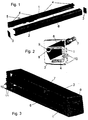
- the housing according to the invention shown in Figure 1 is made essentially from a monthly profile 1, a Cover profile 2, two side end plates 3 and several holding profiles 4.
- a Actuator is as a locking drive 5 and a other than chain drive 6 for tilting the window educated.
- the two drives differ because they serve different purposes, both internally Structure as well as externally.
- the chain drive for example, is used to tilt the Window. It is necessary that this drive can swivel as the drive is on a Circular arc with the tilting Fesner moves while the pivot point on the frame remains fixed.
- Figure 2 shows such a pivoted chain drive within the housing according to the invention as a section.
- the chain of the Drive is at its chain end 7 with that illustrated window sash connected.
- When tilting the drive 6 moves on a circular arc, so that the chain drive 6 also pivots.
- it is Holding profile with a circular bearing opening 8 provided, in which a laterally on the housing of the Actuator mounted bearing pin 9 engages.
- a laterally on the housing of the Actuator mounted bearing pin 9 engages.
- the Inverse kinematics for an expert is obviously also an assembly of the Drive possible on the window frame, then the Inverse kinematics.
- the holder can be seen more clearly in FIG. 3.
- the contour of the mounting profile 1 is clear in Figure 4 recognizable.
- the lower groove 12 is used for marking Insert the mounting holes between the Skirting boards 10.
- the grooves 13, 14, 15 are used for fixing of the holding profile 4.
- One engages in these grooves spring 16 provided off-center on the holding profile 4 ( Figure 6).
- the U-shaped cover profile is also available as Extruded profile formed.
- the free legs of the open U can easily spring open.
- Sliding surfaces 17 and locking grooves 18 are provided.
- the holding profile 4 is a strong u-shaped Extruded profile shaped.
- the three legs of the U circumscribe three sides of a rectangle.
- the resulting contour can be a correspondingly shaped one Counterpart of an actuator added angularly become.
- For swiveling mounting of an actuator is however at the end of a free leg one molded tubular opening 20 which as a bearing appropriately shaped bearing pin 9 ( Figure 7) is used and picks up this journal.
- a marking groove 21 facilitates the installation of mounting holes.
- the location of the individual parts of the invention The housing relative to one another can be clearly seen in FIG. 7.
- the spring 16 of the holding profile 4 engages in this Representation in the fixing groove 15.
- the fixing grooves 14 and 13 represent two more clearly defined possible locations of the holding profile 4. After turning the holding profile 4 three other possible locations are around 180 degrees Are defined. In this way there is a number possible fixed installation variants of the actuators, the for the majority of all practical cases is sufficient and thus avoids custom-made products.
- FIGS. 8 and 9 show two mounting variants of the housing according to the invention with different Actuators shown in section.
- Figure 9 shows the mounting situation of the invention Housing with a chain drive.
- a window sash 22 with not shown screws attached, as before described, cut the axis of the marking groove 12.
- the holding profile 4 with the spring 16 engages in the Fixing groove 15 a.
- the chain drive 6 is so high installed that the chain end 7 with a Fastening part of an associated window frame 23 can be connected.
- the window sash 22 are in Area of the chain of course corresponding beforehand Make openings.
- the same mounting profile 1 With the same axial position of the mounting profile 1 can thus the two different drives, namely the Chain drive 6 and the locking drive 5 in different axis position to the window sash 22 the same mounting profile 1 can be arranged. You leave advantageous and visually appealing one after the other in the same housing according to the invention accommodate.
- the cover profile 2 withdraws the drives the direct view.
- the individual profile parts can advantageously be produced by extrusion.
- a housing has been created that is also universal for the inexpensive retrofitting of Suitable for windows with actuators and beyond allows an aesthetically pleasing attachment.
Landscapes
- Power-Operated Mechanisms For Wings (AREA)
- Lock And Its Accessories (AREA)
- Window Of Vehicle (AREA)
Abstract
Description
- Figur 1:
- das erfindungsgemäße Gehäuse in Explosionsdarstellung mit zwei unterschiedlichen Stellantrieben,
- Figur 2:
- einen Schnitt durch das erfindungsgemäße Gehäuse mit geschwenktem Stellantrieb,
- Figur 3:
- eine perspektivische Ansicht des erfindungsgemäßen Gehäuses mit geschwenktem Stellantrieb,
- Figur 4:
- eine perspektivische Ansicht des Montageprofils,
- Figur 5:
- eine perspektivische Ansicht eines Deckelprofils,
- Figur 6
- : die perspektivische Ansicht eines Halteprofils,
- Figur 7:
- einen Schnitt durch das erfindungsgemäße Gehäuse,
- Figur 8:
- einen Schnitt durch eine Einbausituation des erfindungsgemäßen Gehäuses mit Fensterflügel und Fensterrahmen und
- Figur 9:
- einen Schnitt durch eine Einbausituation des erfindungsgemäßen Gehäuses mit Fensterflügel und Fensterrahmen.
- 1
- Montageprofil
- 2
- Deckelprofil
- 3
- Abschlußplatte
- 4
- Halteprofil
- 5
- Verriegelungsantrieb
- 6
- Kettenantrieb
- 7
- Kettenende
- 8
- Lageröffnung
- 9
- Lagerzapfen
- 10
- Fußleisten
- 11
- Befestigungsbohrung
- 12
- Markierungsnut
- 13
- Fixiernut
- 14
- Fixiernut
- 15
- Fixiernut
- 16
- Feder
- 17
- Aufgleitfläche
- 18
- Rastnut
- 19
- Halteleiste
- 20
- Öffnung
- 21
- Markierungsnut
- 22
- Fensterflügel
- 23
- Fensterrahmen
- 24
- Betätigungsarm
Claims (15)
- Gehäuse zur Befestigung von Stellantrieben an Fenstern, insbesondere für die Betätigung von Dreh-Kipp-Fenstern, dadurch gekennzeichnet, daß das Gehäuse aus mindestens einem Montageprofil (1) zur Befestigung des Stellantriebs (5, 6) und einem Deckelprofil (2) zur Abdeckung des Stellantriebs (5, 6) besteht, wobei mindestens eines der Profile vorzugsweise als Strangpreßprofil ausgebildet ist.
- Gehäuse nach Anspruch 1, dadurch gekennzeichnet, daß mindestens eine seitliche Abschlußkappe (3) vorgesehen ist.
- Gehäuse nach Anspruch 1 oder 2, dadurch gekennzeichnet, daß das Deckelprofil (2) und das Montageprofil (1) aufeinander abgestimmte Formelemente (17, 18, 19) aufweisen, die ein Fügen der beiden Teile (1, 2) durch Aufgleiten und Einrasten ermöglichen.
- Gehäuse nach Anspruch 1, 2 oder 3, dadurch gekennzeichnet, daß ein Halteprofil (4) zur Halterung des Stellantriebs (5, 6) vorgesehen ist, das vorzugsweise als Strangpreßprofil ausgebildet ist.
- Gehäuse nach Anspruch 4, dadurch gekennzeichnet, daß das Halteprofil (4) eine Kontur aufweist, die an seitliche Formelemente des Stellantriebs (5, 6) angepaßt sind und zur Aufnahme dieser dienen.
- Gehäuse nach Anspruch 5, dadurch gekennzeichnet, daß ein Teil der Kontur als ein Lager (8) zur schwenkbaren Aufnahme eines entsprechenden Gegenstücks (9) des Stellantriebs ausgebildet ist und vorzugsweise als runde Öffnung (8) geformt ist.
- Gehäuse nach Anspruch 4, 5 oder 6, dadurch gekennzeichnet, daß ein Stellantrieb vorgesehen ist, dessen Gehäuse ein an das Lagerteil (8) des Halteprofil angepaßtes Lagerelement (9) aufweist, das vorzugsweise als Zapfen ausgebildet ist.
- Gehäuse nach Anspruch 4, 5, 6 oder 7, dadurch gekennzeichnet, daß ein anderer Teil der Kontur des Halteprofils als Teil eines Polygons zur fixierten Aufnahme eines entsprechenden Gehäuseteils des Stellantriebs geformt ist, vorzugsweise als Teil eines Rechtecks geformt ist, insbesondere als U-förmiges Strangpreßprofil.
- Gehäuse nach Anspruch 1, 2, 3, 4, 5, 6, 7 oder 8, dadurch gekennzeichnet, daß das Montageprofil (1) und das Halteprofil (4) aufeinander abgestimmte Nut- (13, 14, 15) und Feder-Elemente (16) zur gegenseitigen Fixierung aufweist.
- Gehäuse nach einem oder mehreren der vorhergehenden Ansprüche, dadurch gekennzeichnet, daß die Nut (13, 14, 15) und/oder die Feder (16) des Halteprofils (4) und/oder Montageprofils (1) außermittig angeordnet sind.
- Gehäuse nach einem oder mehreren der vorhergehenden Ansprüche, dadurch gekennzeichnet, daß das Montageprofil (1) zwei voneinander beabstandete Fußleisten (10) aufweist.
- Gehäuse nach einem oder mehreren der vorhergehenden Ansprüche, dadurch gekennzeichnet, daß das Montageprofil (1) und/oder das Halteprofil (4) Markierungsnuten (12) zum erleichterten Bohren von Befestigungsöffnungen (11) aufweist.
- Fenster mit mindestens einem Stellantrieb in einem Gehäuse gemäß einem der Ansprüche 1 bis 12, dadurch gekennzeichnet, daß der Stellantrieb (5, 6) auf einem Montageprofil (1) befestigt ist, das an einem Fensterflügel (22) eines Gebäudefensters angebracht ist.
- Fenster nach Anspruch 13, dadurch gekennzeichnet, daß das Montageprofil (1) auf einer Gebäudeinnenseite des Fensterflügels (22) angebracht ist.
- Fenster nach Anspruch 13 oder 14, dadurch gekennzeichnet, daß das Montageprofil (1) von einem Deckelprofil (2) abgedeckt ist, das sich über die gesamte Seitenlänge des Fensterflügels (22) erstreckt.
Applications Claiming Priority (2)
| Application Number | Priority Date | Filing Date | Title |
|---|---|---|---|
| DE29806108U DE29806108U1 (de) | 1998-04-03 | 1998-04-03 | Gehäuse zur Befestigung von Stellantrieben zur Betätigung von Fenstern |
| DE29806108U | 1998-04-03 |
Publications (3)
| Publication Number | Publication Date |
|---|---|
| EP0947657A2 true EP0947657A2 (de) | 1999-10-06 |
| EP0947657A3 EP0947657A3 (de) | 2000-03-29 |
| EP0947657B1 EP0947657B1 (de) | 2003-10-08 |
Family
ID=8055257
Family Applications (1)
| Application Number | Title | Priority Date | Filing Date |
|---|---|---|---|
| EP99106303A Expired - Lifetime EP0947657B1 (de) | 1998-04-03 | 1999-03-26 | Gehäuse zur Befestigung von Stellantrieben zur Betätigung von Fenstern |
Country Status (3)
| Country | Link |
|---|---|
| EP (1) | EP0947657B1 (de) |
| AT (1) | ATE251707T1 (de) |
| DE (2) | DE29806108U1 (de) |
Cited By (1)
| Publication number | Priority date | Publication date | Assignee | Title |
|---|---|---|---|---|
| US20220195781A1 (en) * | 2020-04-16 | 2022-06-23 | Hall Labs Llc | Automated windows systems and anchors therefor |
Families Citing this family (2)
| Publication number | Priority date | Publication date | Assignee | Title |
|---|---|---|---|---|
| GB2623684A (en) * | 2021-06-28 | 2024-04-24 | Assa Abloy New Zealand Ltd | Actuator |
| IT202300007242A1 (it) * | 2023-04-14 | 2024-10-14 | Ultraflex Control Systems S R L | Sistema perfezionato per l’apertura e chiusura di ante di finestre, porte o simili |
Citations (2)
| Publication number | Priority date | Publication date | Assignee | Title |
|---|---|---|---|---|
| DE29706637U1 (de) | 1996-04-17 | 1997-06-19 | V. Kann Rasmussen Industri A/S, Soeborg | Motorisch getriebenes Drehkippfenster |
| DE29622922U1 (de) | 1996-05-31 | 1997-07-24 | esco Metallbaubeschlag-Handel GmbH, 71254 Ditzingen | Antriebsvorrichtung für ein Kipp- oder Klappfenster |
Family Cites Families (9)
| Publication number | Priority date | Publication date | Assignee | Title |
|---|---|---|---|---|
| DE2946114A1 (de) * | 1979-11-15 | 1981-05-21 | Brown, Boveri & Cie Ag, 6800 Mannheim | Gehaeuse fuer elektrische bauteile |
| DE8631164U1 (de) * | 1986-11-21 | 1987-01-15 | W. Hautau GmbH, 3068 Helpsen | Ausstellschere für aufliegende Oberlichtöffner |
| DE9213671U1 (de) * | 1991-11-11 | 1992-12-03 | Tridonic-Bauelemente GmbH, Dornbirn | Gehäuse für eine elektronische Schaltungsanordnung |
| DE9114625U1 (de) * | 1991-11-23 | 1992-01-16 | Gretsch-Unitas GmbH Baubeschläge, 7257 Ditzingen | Stellantrieb mit Elektromotor, insbesondere für Fenster, Türen, Markisen, Rolladen o.dgl. |
| DE4213436A1 (de) * | 1992-04-23 | 1993-10-28 | Vero Electronics Gmbh | Kassette für ein Normgehäuse |
| FR2701732B1 (fr) * | 1993-02-19 | 1995-04-21 | Houdaille Lelaurain | Dispositif ouvre-porte électrique. |
| DE4314146C2 (de) * | 1993-04-29 | 1996-03-21 | Webasto Karosseriesysteme | Vorrichtung zum Verstellen von bewegbaren Teilen an Fahrzeugen |
| DE19500944C2 (de) * | 1994-08-26 | 2003-07-03 | Geze Gmbh | Antrieb und Schließfedereinrichtung für einen Flügel einer Tür, Fenster oder dergleichen |
| DE19707680C1 (de) * | 1997-02-26 | 1998-03-05 | Loh Kg Rittal Werk | Kleingehäuse, insbesondere Kabelanschluß- und Kabelverteilergehäuse |
-
1998
- 1998-04-03 DE DE29806108U patent/DE29806108U1/de not_active Expired - Lifetime
-
1999
- 1999-03-26 EP EP99106303A patent/EP0947657B1/de not_active Expired - Lifetime
- 1999-03-26 DE DE59907247T patent/DE59907247D1/de not_active Expired - Fee Related
- 1999-03-26 AT AT99106303T patent/ATE251707T1/de not_active IP Right Cessation
Patent Citations (2)
| Publication number | Priority date | Publication date | Assignee | Title |
|---|---|---|---|---|
| DE29706637U1 (de) | 1996-04-17 | 1997-06-19 | V. Kann Rasmussen Industri A/S, Soeborg | Motorisch getriebenes Drehkippfenster |
| DE29622922U1 (de) | 1996-05-31 | 1997-07-24 | esco Metallbaubeschlag-Handel GmbH, 71254 Ditzingen | Antriebsvorrichtung für ein Kipp- oder Klappfenster |
Cited By (2)
| Publication number | Priority date | Publication date | Assignee | Title |
|---|---|---|---|---|
| US20220195781A1 (en) * | 2020-04-16 | 2022-06-23 | Hall Labs Llc | Automated windows systems and anchors therefor |
| US12123243B2 (en) * | 2020-04-16 | 2024-10-22 | Hall Labs Llc | Automated windows systems and anchors therefor |
Also Published As
| Publication number | Publication date |
|---|---|
| DE29806108U1 (de) | 1999-07-29 |
| ATE251707T1 (de) | 2003-10-15 |
| EP0947657B1 (de) | 2003-10-08 |
| DE59907247D1 (de) | 2003-11-13 |
| EP0947657A3 (de) | 2000-03-29 |
Similar Documents
| Publication | Publication Date | Title |
|---|---|---|
| EP0444084B1 (de) | In türen und wände einsetzbare durchreichevorrichtung | |
| EP0589170B1 (de) | Treibstangenbeschlag für Fenster, Türen od. dgl. | |
| DE8702660U1 (de) | Fenster- oder Tür-Konstruktion mit einem bewegbar gehaltenen, verriegelbaren Flügel | |
| DE202014000876U1 (de) | Beschlag eines zumindest hebbaren, vorzugsweise aber auch verschiebbaren Flügels von Fenstern oder Türen | |
| DE3600211C1 (de) | Fenster- und Tuerbeschlag | |
| EP0440987B2 (de) | Treibstangengetriebe | |
| EP4473180B1 (de) | Verlagerungsvorrichtung zur zwangsweisen verlagerung eines flügels, insbesondere eines schiebeflügels, eines fensters oder einer tür | |
| EP3759301A1 (de) | Vorrichtung zur abdeckung eines schiebeflügels oder verschiebbaren hebe-schiebeflügels eines fensters oder einer tür | |
| EP0947657B1 (de) | Gehäuse zur Befestigung von Stellantrieben zur Betätigung von Fenstern | |
| DE202013008784U1 (de) | Beschlag eines zumindest hebbaren, vorzugsweise aber auch verschiebbaren Flügels von Fenstern oder Türen | |
| DE19602025C2 (de) | Verfahren zum Herstellen eines Flügelrahmens für ein Fenster oder eine Tür, sowie Schubstangenbeschlag zur Verwendung für das Verfahren | |
| DE69402465T2 (de) | Fensterrahmen mit Betätigungsvorrichtung für Riegelstangenverschlüsse | |
| DE3004854C2 (de) | Feststellvorrichtung für Flügel von Fenstern, Türen o.dgl. in wenigstens einer Spaltlüftungsstellung | |
| EP0899401B1 (de) | Befestigungseinrichtung | |
| EP0945579A2 (de) | Lüftungseinrichtung | |
| DE602004004982T2 (de) | Eckumlenkung für Türen und Fenster | |
| EP1076140B1 (de) | Verschlussbetätiger für Flügel von Fenstern, Türen od. dgl., insbesondere von Schiebeflügeln | |
| DE202021105180U1 (de) | Fenster | |
| DE4100435C2 (de) | ||
| AT397412B (de) | Antriebsvorrichtung für lamellenjalousien, rollvorhänge od.dgl. | |
| EP0667432B1 (de) | Zusatzverriegelungsvorrichtung für ein Fenster, eine Tür o.dgl. | |
| EP1582671B1 (de) | Getriebe für Flügel von Fenstern oder Türen | |
| CH688103A5 (de) | Tuer. | |
| EP1746235A2 (de) | Beschlaganordnung | |
| DE2431616A1 (de) | Verschlussgetriebe, insbesondere fuer einen fluegel eines fensters, einer tuer o.dgl. |
Legal Events
| Date | Code | Title | Description |
|---|---|---|---|
| PUAI | Public reference made under article 153(3) epc to a published international application that has entered the european phase |
Free format text: ORIGINAL CODE: 0009012 |
|
| AK | Designated contracting states |
Kind code of ref document: A2 Designated state(s): AT BE CH CY DE DK ES FI FR GB GR IE IT LI LU MC NL PT SE |
|
| AX | Request for extension of the european patent |
Free format text: AL;LT;LV;MK;RO;SI |
|
| PUAL | Search report despatched |
Free format text: ORIGINAL CODE: 0009013 |
|
| AK | Designated contracting states |
Kind code of ref document: A3 Designated state(s): AT BE CH CY DE DK ES FI FR GB GR IE IT LI LU MC NL PT SE |
|
| AX | Request for extension of the european patent |
Free format text: AL;LT;LV;MK;RO;SI |
|
| 17P | Request for examination filed |
Effective date: 20000417 |
|
| AKX | Designation fees paid |
Free format text: AT BE CH CY DE DK ES FI FR GB GR IE IT LI LU MC NL PT SE |
|
| AXX | Extension fees paid |
Free format text: AL PAYMENT 20000701;LT PAYMENT 20000701;LV PAYMENT 20000701;MK PAYMENT 20000701;RO PAYMENT 20000701;SI PAYMENT 20000701 |
|
| 17Q | First examination report despatched |
Effective date: 20020910 |
|
| RAP1 | Party data changed (applicant data changed or rights of an application transferred) |
Owner name: VKR HOLDING A/S |
|
| GRAH | Despatch of communication of intention to grant a patent |
Free format text: ORIGINAL CODE: EPIDOS IGRA |
|
| GRAS | Grant fee paid |
Free format text: ORIGINAL CODE: EPIDOSNIGR3 |
|
| GRAA | (expected) grant |
Free format text: ORIGINAL CODE: 0009210 |
|
| AK | Designated contracting states |
Kind code of ref document: B1 Designated state(s): AT BE CH CY DE DK ES FI FR GB GR IE IT LI LU MC NL PT SE |
|
| AX | Request for extension of the european patent |
Extension state: AL LT LV MK RO SI |
|
| PG25 | Lapsed in a contracting state [announced via postgrant information from national office to epo] |
Ref country code: IT Free format text: LAPSE BECAUSE OF FAILURE TO SUBMIT A TRANSLATION OF THE DESCRIPTION OR TO PAY THE FEE WITHIN THE PRESCRIBED TIME-LIMIT;WARNING: LAPSES OF ITALIAN PATENTS WITH EFFECTIVE DATE BEFORE 2007 MAY HAVE OCCURRED AT ANY TIME BEFORE 2007. THE CORRECT EFFECTIVE DATE MAY BE DIFFERENT FROM THE ONE RECORDED. Effective date: 20031008 Ref country code: IE Free format text: LAPSE BECAUSE OF FAILURE TO SUBMIT A TRANSLATION OF THE DESCRIPTION OR TO PAY THE FEE WITHIN THE PRESCRIBED TIME-LIMIT Effective date: 20031008 Ref country code: FI Free format text: LAPSE BECAUSE OF FAILURE TO SUBMIT A TRANSLATION OF THE DESCRIPTION OR TO PAY THE FEE WITHIN THE PRESCRIBED TIME-LIMIT Effective date: 20031008 Ref country code: CY Free format text: LAPSE BECAUSE OF FAILURE TO SUBMIT A TRANSLATION OF THE DESCRIPTION OR TO PAY THE FEE WITHIN THE PRESCRIBED TIME-LIMIT Effective date: 20031008 |
|
| REG | Reference to a national code |
Ref country code: GB Ref legal event code: FG4D Free format text: NOT ENGLISH |
|
| REG | Reference to a national code |
Ref country code: CH Ref legal event code: EP |
|
| REG | Reference to a national code |
Ref country code: IE Ref legal event code: FG4D Free format text: GERMAN |
|
| REF | Corresponds to: |
Ref document number: 59907247 Country of ref document: DE Date of ref document: 20031113 Kind code of ref document: P |
|
| PG25 | Lapsed in a contracting state [announced via postgrant information from national office to epo] |
Ref country code: SE Free format text: LAPSE BECAUSE OF FAILURE TO SUBMIT A TRANSLATION OF THE DESCRIPTION OR TO PAY THE FEE WITHIN THE PRESCRIBED TIME-LIMIT Effective date: 20040108 Ref country code: GR Free format text: LAPSE BECAUSE OF FAILURE TO SUBMIT A TRANSLATION OF THE DESCRIPTION OR TO PAY THE FEE WITHIN THE PRESCRIBED TIME-LIMIT Effective date: 20040108 Ref country code: DK Free format text: LAPSE BECAUSE OF FAILURE TO SUBMIT A TRANSLATION OF THE DESCRIPTION OR TO PAY THE FEE WITHIN THE PRESCRIBED TIME-LIMIT Effective date: 20040108 |
|
| REG | Reference to a national code |
Ref country code: CH Ref legal event code: NV Representative=s name: PATENTANWALTSBUERO RENFER-VONNEMANN |
|
| PG25 | Lapsed in a contracting state [announced via postgrant information from national office to epo] |
Ref country code: ES Free format text: LAPSE BECAUSE OF FAILURE TO SUBMIT A TRANSLATION OF THE DESCRIPTION OR TO PAY THE FEE WITHIN THE PRESCRIBED TIME-LIMIT Effective date: 20040119 |
|
| GBT | Gb: translation of ep patent filed (gb section 77(6)(a)/1977) |
Effective date: 20040116 |
|
| LTIE | Lt: invalidation of european patent or patent extension |
Effective date: 20031008 |
|
| PG25 | Lapsed in a contracting state [announced via postgrant information from national office to epo] |
Ref country code: LU Free format text: LAPSE BECAUSE OF NON-PAYMENT OF DUE FEES Effective date: 20040326 |
|
| PG25 | Lapsed in a contracting state [announced via postgrant information from national office to epo] |
Ref country code: MC Free format text: LAPSE BECAUSE OF NON-PAYMENT OF DUE FEES Effective date: 20040331 |
|
| REG | Reference to a national code |
Ref country code: IE Ref legal event code: FD4D |
|
| ET | Fr: translation filed | ||
| PLBE | No opposition filed within time limit |
Free format text: ORIGINAL CODE: 0009261 |
|
| STAA | Information on the status of an ep patent application or granted ep patent |
Free format text: STATUS: NO OPPOSITION FILED WITHIN TIME LIMIT |
|
| 26N | No opposition filed |
Effective date: 20040709 |
|
| REG | Reference to a national code |
Ref country code: CH Ref legal event code: PCAR Representative=s name: PATENTANWALTSBUERO URSULA RENFER-VONNEMANN; ROSWIESENSTRASSE 61; 8309 BIRCHWIL-NUERENSDORF (CH) |
|
| REG | Reference to a national code |
Ref country code: CH Ref legal event code: PFA Owner name: VKR HOLDING A/S Free format text: VKR HOLDING A/S#TOBAKSVEJEN 10#2860 SOEBORG (DK) -TRANSFER TO- VKR HOLDING A/S#BREELTEVEJ 18#2970 HOERSHOLM (DK) |
|
| PG25 | Lapsed in a contracting state [announced via postgrant information from national office to epo] |
Ref country code: PT Free format text: LAPSE BECAUSE OF NON-PAYMENT OF DUE FEES Effective date: 20040308 |
|
| PGFP | Annual fee paid to national office [announced via postgrant information from national office to epo] |
Ref country code: AT Payment date: 20090317 Year of fee payment: 11 |
|
| PGFP | Annual fee paid to national office [announced via postgrant information from national office to epo] |
Ref country code: NL Payment date: 20090317 Year of fee payment: 11 |
|
| PGFP | Annual fee paid to national office [announced via postgrant information from national office to epo] |
Ref country code: GB Payment date: 20090325 Year of fee payment: 11 Ref country code: CH Payment date: 20090316 Year of fee payment: 11 |
|
| PGFP | Annual fee paid to national office [announced via postgrant information from national office to epo] |
Ref country code: DE Payment date: 20090320 Year of fee payment: 11 |
|
| PGFP | Annual fee paid to national office [announced via postgrant information from national office to epo] |
Ref country code: BE Payment date: 20090430 Year of fee payment: 11 |
|
| PGFP | Annual fee paid to national office [announced via postgrant information from national office to epo] |
Ref country code: FR Payment date: 20090312 Year of fee payment: 11 |
|
| BERE | Be: lapsed |
Owner name: *VKR HOLDING A/S Effective date: 20100331 |
|
| REG | Reference to a national code |
Ref country code: NL Ref legal event code: V1 Effective date: 20101001 |
|
| REG | Reference to a national code |
Ref country code: CH Ref legal event code: PL |
|
| GBPC | Gb: european patent ceased through non-payment of renewal fee |
Effective date: 20100326 |
|
| PG25 | Lapsed in a contracting state [announced via postgrant information from national office to epo] |
Ref country code: AT Free format text: LAPSE BECAUSE OF NON-PAYMENT OF DUE FEES Effective date: 20100326 |
|
| REG | Reference to a national code |
Ref country code: FR Ref legal event code: ST Effective date: 20101130 |
|
| PG25 | Lapsed in a contracting state [announced via postgrant information from national office to epo] |
Ref country code: NL Free format text: LAPSE BECAUSE OF NON-PAYMENT OF DUE FEES Effective date: 20101001 Ref country code: FR Free format text: LAPSE BECAUSE OF NON-PAYMENT OF DUE FEES Effective date: 20100331 |
|
| PG25 | Lapsed in a contracting state [announced via postgrant information from national office to epo] |
Ref country code: LI Free format text: LAPSE BECAUSE OF NON-PAYMENT OF DUE FEES Effective date: 20100331 Ref country code: DE Free format text: LAPSE BECAUSE OF NON-PAYMENT OF DUE FEES Effective date: 20101001 Ref country code: CH Free format text: LAPSE BECAUSE OF NON-PAYMENT OF DUE FEES Effective date: 20100331 Ref country code: BE Free format text: LAPSE BECAUSE OF NON-PAYMENT OF DUE FEES Effective date: 20100331 |
|
| PG25 | Lapsed in a contracting state [announced via postgrant information from national office to epo] |
Ref country code: GB Free format text: LAPSE BECAUSE OF NON-PAYMENT OF DUE FEES Effective date: 20100326 |